

Sur-Gard SG System II Operating Manual

Sur-Gard System II
Single Line Network Receiver
Operating Manual
WARNING: This manual contains information on limitations regarding
product use and function and information on the limitations as to
liability of the manufacturer. The entire manual should be carefully read.
version 2.0

GENERAL DESCRIPTION of the EQUIPMENT and CLASSIFICATION.
SYSTEM II - SAFETY INSTRUCTIONS
The SYSTEM II equipment is a CLASS 1, DESK-TOP (MOVABLE) or RACK-MOUNTED (FIXED - STATIONARY),
EQUIPMENT, PLUGGABLE TYPE A using a DETACHABLE
POWER SUPPLY CORD; it is designed to be INSTALLED,
OPERATED and MAINTAINED by SERVICE PERSONS
ONLY. [person having appropriate technical training and experience necessary to be aware of hazards to which that person may
be exposed in performing a task and of measures to minimize the
risks to that person or other persons]. The equipment SYSTEM II
shall be installed in RESTRICTED ACCESS LOCATIONS
within an environment that provides the Pollution Degree max 2,
and overvoltages category II – non-hazardous locations, indoor
only.
The POWER SUPPLY CORD serves as a means of disconnection from the MAINS. The OUTLET used to power the equipment shall be installed near the equipment, and shall be easily
accessible. The equipment must be connected to a socket-outlet
with a protective earthing connection!
WHEN RACK-MOUNTED, IT IS THE RESPONSIBILITY OF
THE INSTALLER TO ENSURE THAT THE FINAL ASSEMBLY that includes SYSTEM II EQUIPMENT IS COMPLIANT
with the applicable requirements from the point of view of STABILITY; the rack-mounted equipment must be secured to the
building structure before operation; all wiring and installation
shall be in accordance with electrical codes acceptable to the
authorities that have jurisdiction where the equipment is
installed, serviced and operated; not more than 3 (three) system II
units mounted within the same rack shall be powered from the
same branch circuit; use a different branch circuit for any group
larger than 3 (three) units.
Interconnecting cables shall be routed in a manner that prevents:
excessive strain on wire and on terminal connections; loosening
of terminal connections; damage of conductor insulation.
This product uses Lithium Batteries. Improper handling of lithium batteries may result in heat generation, explosion or fire,
which may lead to personal injuries.
CONNECTION TO THE MAINS:
1. Connect first the DETACHABLE POWER SUPPLY CORD to
the IEC 320 connector located on SYSTEM II equipment.
CAUTION: The Ethernet communication lines must be connected first to an Approved (acceptable to the local authorities)
type NID (Network Interface Device) before leaving the premises (e.g., UL installations, UL60950 Listed NID for ULC Installations CAN/CSA C22.2 No. 60950-1 Listed NID).
NO REPAIRS IN THE FIELD ARE ALLOWED. THE EQUIPMENT SYSTEM II MUST BE RETURNED TO THE MANUFACTURER FOR REPAIRS.
FCC Compliance Statement
CAUTION: Changes or modifications not expressly approved by Digital Security Controls
could void your authority to use this equipment.
This equipment has been tested and found to comply with the limits for a Class B digital device,
pursuant to Part 15 of the FCC Rules. These limits are designed to provide reasonable protection
against harmful interference in a residential installation. This equipment generates, uses and can
radiate radio frequency energy and, if not installed and used in accordance with the instructions,
may cause harmful interference to radio communications. However, there is no guarantee that
interference will not occur in a particular installation. If this equipment does cause harmful
interference to radio or television reception, which can be determined by turning the equipment
This Class B digital apparatus complies with Canadian ICES-003.
Cet appareil numérique de la classe B est conforme à la norme NMB-003 du Canada.
off and on, the user is encouraged to try to correct the interference by one or more of the following measures:
• Re-orient the receiving antenna.
• Increase the separation between the equipment and receiver.
• Connect the equipment into an outlet on a circuit different from that to which the receiver is
connected.
• Consult the dealer or an experienced radio/television technician for help.
The user may find the following booklet prepared by the FCC useful: “How to Identify and
Resolve Radio/Television Interference Problems”. This booklet is available from the U.S. Government Printing Office, Washington D.C. 20402, Stock # 004-000-00345-4.

Table of Contents
Section 1 - Introduction........................................1
1.1 Features .............................................................. 1
1.2 Software Compatibility..................................... 1
1.3 Approvals ........................................................... 1
1.3.1 Industry Approvals ................................................1
1.4 Specifications ..................................................... 3
1.5 Out of Box .......................................................... 3
Section 2 - Installation..........................................4
2.1 Controls and Indicators ..................................... 4
2.2 Set Up and Testing ............................................. 6
Section 3 - Operation/Operating Modes..............7
3.1 Active Mode ....................................................... 7
3.2 Manual Mode ..................................................... 7
3.3 Program Category.............................................. 7
Password ..............................................................7
3.3.2 User Interface .......................................................7
3.3.3 Top Level Menu ....................................................7
3.3.4 System Functions Menu ........................................8
3.3.5 Miscellaneous LED Indicators.................................9
Option [014]: Receiver Number ................................... 13
Option [015]: Printer Test ............................................13
Option [020]: Mask UPS AC ........................................ 13
Option [021]: Mask UPS BAT.............................................13
Option [024]: Mask SG TCP/IP..................................... 13
Option [025]: Mask SG Serial ......................................14
Option [028]: Mask TCP Printer................................... 14
Option [029]: Mask Parallel Printer ..............................14
Option [02A]: Mask Serial Printer ................................ 14
Option [02F]: Automation Mode ................................. 14
Option [030]: Printer Mode ......................................... 16
Option [031]: ACK Wait .............................................. 16
Option [032]: Date Format .......................................... 16
Options [037] and [038]: Product ID Keys #1, #2 ......... 16
Option [039]: Mask USB Printer................................... 16
Option [03A]: Programmable I/O................................. 16
Option [03B]: Last Message On ................................... 16
Option [03C]: LCD Backlight Colour............................ 17
Option [03D]: Key Backlight Colour............................. 17
Option [041]: System Number Length ......................... 17
Option [042]: Busy Out ............................................... 17
Option [043]: System Protocol ID................................. 17
Section 5 - System Options................................ 10
5.1 IP Option Index ................................................ 19
Section 4 - System Options.................................10
4.1 System Option Index ....................................... 10
4.2 System Options ................................................ 11
Option [001]: LAN IP Address ......................................11
Option [002]: LAN Subnet Mask Address .....................10
Option [003]: LAN Gateway.........................................11
Option [004]: Auto Update Time and Date ..................11
Option [005]: Contrast ................................................11
Option [006]: Password ...............................................11
Option [007]: Automation Baud Rate...........................11
Option [008]: Automation Data Bits.............................11
Option [009]: Automation Parity..................................12
Option [00A]: Serial Printer Format ..............................12
Option [00B]: Serial Baud Rate.....................................12
Option [00C]: Serial Data Bits ......................................12
Option [00D]: Serial Printer Parity.................................12
Option [00F]: B32 Headers...........................................12
Option [00F]: B32 Headers...........................................12
Option [012]: Heartbeat Timer.....................................12
Option [013]: Buzzer Tone ...........................................13
5.2 IP Options ......................................................... 19
Option [110]: Line Card Number - Table 1 ...................20
Option [113]: Transmitter Failure Debounce Time ........ 20
Option [115]: Transmitter Restoral Debounce Time...... 20
Option [119]: Mask Transmitter Restoral...................... 20
Option [11A]: Mask Transmitter Failure........................20
Option [11B]: Mask Transmitter Swap.......................... 20
Option [11C]: Mask Transmitter Unencrypted.............. 20
Option [11D]: Mask Invalid Report ....................................20
Option [11E]: Mask Unknown Account ....................... 20
Option [11F]: Mask Supervised Acc Exceeded .............. 21
Option [120]: Mask Transmitter Deleted...................... 21
Option [13A]: Account Port......................................... 21
Option [140]: Account Password................................. 21
Option [144]: DNIS Replacement of RRLLL ................... 21
Option [146]: Account Digit Strip ................................ 21
Option [147]: SIM ID Output .............................................22
Appendix A - Events and Messages ........................... 23
Appendix B - Ports ....................................................... 25

WARNING Please Read Carefully
Note to Installers
This warning contains vital information. As the only individual in contact with system users, it is
your responsibility to bring each item in this warning to the attention of the users of this system.
System Failures
This system has been carefully designed to be as effective as possible. There are circumstances, however, involving fire, burglary, or other types of emergencies where it may not provide protection. Any
alarm system of any type may be compromised deliberately or may fail to operate as expected for a
variety of reasons. Some but not all of these reasons may be:
- Inadequate Installation
A security system must be installed properly in order to provide adequate protection. Every installation should be evaluated by a security professional to ensure that all access points and areas are covered. Locks and latches on windows and doors must be secure and operate as intended. Windows,
doors, walls, ceilings and other building materials must be of sufficient strength and construction to
provide the level of protection expected. A reevaluation must be done during and after any construction activity. An evaluation by the fire and/or police department is highly recommended if this service is available.
- Criminal Knowledge
This system contains security features which were known to be effective at the time of manufacture.
It is possible for persons with criminal intent to develop techniques which reduce the effectiveness of
these features. It is important that a security system be reviewed periodically to ensure that its features remain effective and that it be updated or replaced if it is found that it does not provide the protection expected.
- Access by Intruders
Intruders may enter through an unprotected access point, circumvent a sensing device, evade detection by moving through an area of insufficient coverage, disconnect a warning device, or interfere
with or prevent the proper operation of the system.
- Power Failure
Control units, intrusion detectors, smoke detectors and many other security devices require an adequate power supply for proper operation. If a device operates from batteries, it is possible for the batteries to fail. Even if the batteries have not failed, they must be charged, in good condition and
installed correctly. If a device operates only by AC power, any interruption, however brief, will render that device inoperative while it does not have power. Power interruptions of any length are often
accompanied by voltage fluctuations which may damage electronic equipment such as a security system. After a power interruption has occurred, immediately conduct a complete system test to ensure
that the system operates as intended.
- Failure of Replaceable Batteries
This system’s wireless transmitters have been designed to provide several years of battery life under
normal conditions. The expected battery life is a function of the device environment, usage and type.
Ambient conditions such as high humidity, high or low temperatures, or large temperature fluctuations may reduce the expected battery life. While each transmitting device has a low battery monitor
which identifies when the batteries need to be replaced, this monitor may fail to operate as expected.
Regular testing and maintenance will keep the system in good operating condition.
- Compromise of Radio Frequency (Wireless) Devices
Signals may not reach the receiver under all circumstances which could include metal objects placed
on or near the radio path or deliberate jamming or other inadvertent radio signal interference.
- System Users
A user may not be able to operate a panic or emergency switch possibly due to permanent or temporary physical disability, inability to reach the device in time, or unfamiliarity with the correct operation. It is important that all system users be trained in the correct operation of the alarm system and
that they know how to respond when the system indicates an alarm.
- Smoke Detectors
Smoke detectors that are a part of this system may not properly alert occupants of a fire for a number
of reasons, some of which follow. The smoke detectors may have been improperly installed or positioned. Smoke may not be able to reach the smoke detectors, such as when the fire is in a chimney,
walls or roofs, or on the other side of closed doors. Smoke detectors may not detect smoke from fires
on another level of the residence or building.
Every fire is different in the amount of smoke produced and the rate of burning. Smoke detectors cannot sense all types of fires equally well. Smoke detectors may not provide timely warning of fires
caused by carelessness or safety hazards such as smoking in bed, violent explosions, escaping gas,
improper storage of flammable materials, overloaded electrical circuits, children playing with
matches or arson.
Even if the smoke detector operates as intended, there may be circumstances when there is insufficient warning to allow all occupants to escape in time to avoid injury or death.
- Motion Detectors
Motion detectors can only detect motion within the designated areas as shown in their respective
installation instructions. They cannot discriminate between intruders and intended occupants. Motion
detectors do not provide volumetric area protection. They have multiple beams of detection and
motion can only be detected in unobstructed areas covered by these beams. They cannot detect
motion which occurs behind walls, ceilings, floor, closed doors, glass partitions, glass doors or windows. Any type of tampering whether intentional or unintentional such as masking, painting, or
spraying of any material on the lenses, mirrors, windows or any other part of the detection system
will impair its proper operation.
Passive infrared motion detectors operate by sensing changes in temperature. However their effectiveness can be reduced when the ambient temperature rises near or above body temperature or if
there are intentional or unintentional sources of heat in or near the detection area. Some of these heat
sources could be heaters, radiators, stoves, barbeques, fireplaces, sunlight, steam vents, lighting and
so on.
- Warning Devices
Warning devices such as sirens, bells, horns, or strobes may not warn people or waken someone
sleeping if there is an intervening wall or door. If warning devices are located on a different level of
the residence or premise, then it is less likely that the occupants will be alerted or awakened. Audible
warning devices may be interfered with by other noise sources such as stereos, radios, televisions, air
conditioners or other appliances, or passing traffic. Audible warning devices, however loud, may not
be heard by a hearing-impaired person.
- Telephone Lines
If telephone lines are used to transmit alarms, they may be out of service or busy for certain periods
of time. Also an intruder may cut the telephone line or defeat its operation by more sophisticated
means which may be difficult to detect.
- Insufficient Time
There may be circumstances when the system will operate as intended, yet the occupants will not be
protected from the emergency due to their inability to respond to the warnings in a timely manner. If
the system is monitored, the response may not occur in time to protect the occupants or their belongings.
- Component Failure
Although every effort has been made to make this system as reliable as possible, the system may fail
to function as intended due to the failure of a component.
- Inadequate Testing
Most problems that would prevent an alarm system from operating as intended can be found by regular testing and maintenance. The complete system should be tested weekly and immediately after a
break-in, an attempted break-in, a fire, a storm, an earthquake, an accident, or any kind of construc-
tion activity inside or outside the premises. The testing should include all sensing devices, keypads,
consoles, alarm indicating devices and any other operational devices that are part of the system.
- Security and Insurance
Regardless of its capabilities, an alarm system is not a substitute for property or life insurance. An
alarm system also is not a substitute for property owners, renters, or other occupants to act prudently
to prevent or minimize the harmful effects of an emergency situation.
Limited Warranty
Digital Security Controls warrants the original purchaser that for a period of twelve months from the
date of purchase, the product shall be free of defects in materials and workmanship under normal
use. During the warranty period, Digital Security Controls shall, at its option, repair or replace any
defective product upon return of the product to its factory, at no charge for labour and materials. Any
replacement and/or repaired parts are warranted for the remainder of the original warranty or ninety
(90) days, whichever is longer. The original purchaser must promptly notify Digital Security Controls in writing that there is defect in material or workmanship, such written notice to be received in
all events prior to expiration of the warranty period.
and all software products are sold as a user license under the terms of the software license
agreement included with the product. The Customer assumes all responsibility for the proper
selection, installation, operation and maintenance of any products purchased from DSC. Custom products are only warranted to the extent that they do not function upon delivery. In such
cases, DSC can replace or credit at its option.
International Warranty
The warranty for international customers is the same as for any customer within Canada and the
United States, with the exception that Digital Security Controls shall not be responsible for any customs fees, taxes, or VAT that may be due.
Warranty Procedure
To obtain service under this warranty, please return the item(s) in question to the point of purchase.
All authorized distributors and dealers have a warranty program. Anyone returning goods to Digital
Security Controls must first obtain an authorization number. Digital Security Controls will not accept
any shipment whatsoever for which prior authorization has not been obtained.
Conditions to Void Warranty
This warranty applies only to defects in parts and workmanship relating to normal use. It does not
cover:
• damage incurred in shipping or handling;
• damage caused by disaster such as fire, flood, wind, earthquake or lightning;
• damage due to causes beyond the control of Digital Security Controls such as excessive voltage,
mechanical shock or water damage;
• damage caused by unauthorized attachment, alterations, modifications or foreign objects;
• damage caused by peripherals (unless such peripherals were supplied by Digital Security Con-
trols);
• defects caused by failure to provide a suitable installation environment for the products;
• damage caused by use of the products for purposes other than those for which it was designed;
• damage from improper maintenance;
• damage arising out of any other abuse, mishandling or improper application of the products.
Items Not Covered by Warranty
In addition to the items which void the Warranty, the following items shall not be covered by Warranty: (i) freight cost to the repair centre; (ii) products which are not identified with DSC's product
label and lot number or serial number; (iii) products disassembled or repaired in such a manner as to
adversely affect performance or prevent adequate inspection or testing to verify any warranty claim.
Access cards or tags returned for replacement under warranty will be credited or replaced at DSC's
option. Products not covered by this warranty, or otherwise out of warranty due to age, misuse, or
damage shall be evaluated, and a repair estimate shall be provided. No repair work will be performed
until a valid purchase order is received from the Customer and a Return Merchandise Authorisation
number (RMA) is issued by DSC's Customer Service.
Digital Security Controls’s liability for failure to repair the product under this warranty after a reasonable number of attempts will be limited to a replacement of the product, as the exclusive remedy
for breach of warranty. Under no circumstances shall Digital Security Controls be liable for any special, incidental, or consequential damages based upon breach of warranty, breach of contract, negligence, strict liability, or any other legal theory. Such damages include, but are not limited to, loss of
profits, loss of the product or any associated equipment, cost of capital, cost of substitute or replacement equipment, facilities or services, down time, purchaser’s time, the claims of third parties,
including customers, and injury to property.
the disclaimer of consequential damages. If the laws of such a jurisdiction apply to any claim
by or against DSC, the limitations and disclaimers contained here shall be to the greatest
extent permitted by law. Some states do not allow the exclusion or limitation of incidental or
consequential damages, so that the above may not apply to you.
Disclaimer of Warranties
This warranty contains the entire warranty and shall be in lieu of any and all other warranties,
whether expressed or implied (including all implied warranties of merchantability or fitness for a
particular purpose) And of all other obligations or liabilities on the part of Digital Security Controls Digital Security Controls neither assumes responsibility for, nor authorizes any other person
purporting to act on its behalf to modify or to change this warranty, nor to assume for it any other
warranty or liability concerning this product.
This disclaimer of warranties and limited warranty are governed by the laws of the province of
Ontario, Canada.
WARNING: Digital Security Controls recommends that the entire system be completely tested
on a regular basis. However, despite frequent testing, and due to, but not limited to, criminal
tampering or electrical disruption, it is possible for this product to fail to perform as expected.
Installer’s Lockout
Any products returned to DSC which have the Installer’s Lockout option enabled and exhibit no
other problems will be subject to a service charge.
Out of Warranty Repairs
Digital Security Controls will at its option repair or replace out-of-warranty products which are
returned to its factory according to the following conditions. Anyone returning goods to Digital
Security Controls must first obtain an authorization number. Digital Security Controls will not accept
any shipment whatsoever for which prior authorization has not been obtained.
Products which Digital Security Controls determines to be repairable will be repaired and returned.
A set fee which Digital Security Controls has predetermined and which may be revised from time to
time, will be charged for each unit repaired.
Products which Digital Security Controls determines not to be repairable will be replaced by the
nearest equivalent product available at that time. The current market price of the replacement product
will be charged for each replacement unit.
There is absolutely no warranty on software
The laws of some jurisdictions limit or do not allow
Section 1 - Introduction
1.1 Features
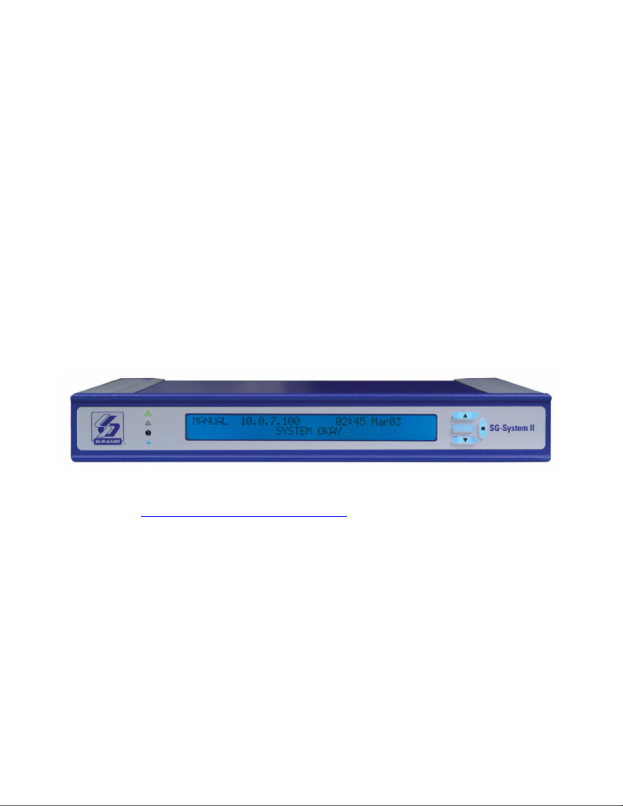
The SG-System II is a single line network receiver intended for remote monitoring of commercial fire and burglary systems. The system can be
configured for “desktop stand-alone” operation (vertical stacking of up to 4 systems) or rack mounting. The SG-System II can monitor up to
1536 accounts including 512 supervised accounts. An additional 1536 IP accounts may be purchased separately with the use of a License key.
NOTE: System must be rack mounted for UL and ULC Listed Installations.
The SG-System II real time clock and calendar stamps all received alarm data which is then transmitted to a central station computer via TCP/IP,
serial port; transmitted directly to a printer using the parallel printer port, serial printer port, USB port to Systems Console Software, TCP port
using Systems Console Software, and viewed on the LCD of the front panel. System configuration can be programmed using a PC with SG-Systems Console Software via TCP or USB connections or locally using the scroll buttons and LCD.
The SG-System II receives alarm information from panels over a LAN/WAN or internet network.
SG-System II features include the following:
• Provides higher line security than conventional dial up panels with the polling feature.
• Provides fast transmission since dialing or handshaking is not required.
• The control panel is the originator of the signals and as such will be the one requesting the ACK from the central station.
• Network trouble detection is displayed on LCD/Printer and automation software.
• Disconnect trouble detection.
• Static IP for programming of the network protocols.
• Data network polling environment for replacement of an existing DVACS network.
• SIA event descriptors are used to transmit information to the central station from the control panel through the PC-Link connection.
• 4 and 10 digit Contact ID.
• A security function communicates to the central station when a module is removed and replaced.
• USB 1.1 connection for Console
• Two IP account tables. The second table adds another 1536 accounts of which 512 can be supervised.
NOTE: For UL/ULC Listed applications maximum 512 supervised accounts can be used.
Figure 1: SG-System II Receiver
1.2 Software Compatibility
The following examples of Central Station automation software are compatible with the SG-System II interface.
Refer to the DSC website “http://www.dsc.com/index.php?n=MonitoringStations” for a comprehensive list of compatible Automation Software
Manunufacturers:
• MAS • MicroKey • GENESYS
• IBS • SIMS II • Bold
• DICE • ABM • S.I.S.
NOTE: Automation connections are considered supplementary per UL864 listing. Compatibility with the central station automation software is intended to be handled under a separate UL1981 software and/or site certification
evaluation.
NOTE: Software version 2.0 of SG-system II must be used with the SG-Systems Console software version 1.1
1.3 Approvals
1.3.1 Industry Approvals
The System II meets the requirements of the following standards:
• UL 1610 Central Station Burglar Alarm Units
• UL 864 Standard for Control Units and Accessories for Fire Alarm Systems
• CAN/ULC-S304-06 Signal Receiving Centre and Premises Burglar Alarm Control Units
• CAN/ULC-S559-04 Equipment for Fire Signal Receiving Centres and Systems
• EN60950-1:2001 Standard for Information Technology Equipment.
• AS/NZS 60950:2000 Information Technology Equipment - Safety
• CISPR22 Information Technology Equipment - Radio Disturbance Characteristics - Limits and Methods of Measurements
• EN50130-4 Immunity requirements for components of fire, intruder and social alarm systems.
1

This equipment shall be installed in accordance with the requirements of NFPA72, NFPA70, and the authority having jurisdiction.
The Equipment is ULC listed for active communication channel security level A4 when used in conjunction with compatible communicators, ULC
listed for the same level of line security (DSC Models T-Link TL250, T-Link TL300, TL265GS, GS2065, TL260GS, GS2060).
Compatible Communicators:
• MAS • MicroKey • GENESYS
• TL150 • TL250 * • BFSM-100M
• TL300 * • GS3055 * • GS3060 *
• TL26X * • GS206X * • KNet
* ULC Listed
For ULC Installations the equipment shall be installed in accordance with the requirements of ULC-S561 and ULC-S301 Standards and the author-
ity having jurisdiction.
UL864 Programming Requirements
Table 6: Table 1: UL864 Programming Requirements
Option number and name Page
Permitted in
UL 864? (Y/N)
Option [013]: Buzzer Tone..............................................13 N Default, Buzzer Off, 1490
Possible
settings
Settings
permitted (UL 864)
ON
Hz, 1990 Hz, 2103 Hz,
2650 Hz, 3149 Hz, 3965
Hz, 4270 Hz, 4530 Hz
Option [020]: Mask UPS AC ...........................................13 N ON/OFF OFF
Option [021]: Mask UPS BAT ..........................................13 N ON/OFF OFF
Option [024]: Mask SG TCP/IP........................................13 N ON/OFF OFF
Option [025]: Mask SG Serial..........................................14 N ON/OFF OFF
Option [028]: Mask TCP Printer......................................14 N ON/OFF OFF
Option [029]: Mask Parallel Printer .................................14 N ON/OFF OFF
Option [02A]: Mask Serial Printer....................................14 N ON/OFF OFF
Option [039]: Mask USB Printer......................................16 N ON/OFF OFF
Option [042]: Busy Out...................................................17 N ON/OFF OFF
Option [113]: Transmitter Failure Debounce Time ..........20 N 001E-FFFF (30-65535 sec) 05A (90 sec)
Option [115]: Transmitter Restoral Debounce Time ........20 N 001E-FFFF (30-65535 sec) 3C (60 sec)
Option [119]: Mask Transmitter Restoral.........................20 N ON/OFF OFF
Option [11A]: Mask Transmitter Failure ..........................20 N ON/OFF OFF
Option [11B]: Mask Transmitter Swap ............................20 N ON/OFF OFF
Option [11C]: Mask Transmitter Unencrypted ................20 N ON/OFF OFF
Option [11D]: Mask Invalid Report..................................20 N ON/OFF OFF
Option [11E]: Mask Unknown Account..........................20 N ON/OFF OFF
Option [11F]: Mask Supervised Acc Exceeded ................21 N ON/OFF OFF
Parallel Printers:
For UL and ULC Listed applications the following UL Listed printers can be used with the SG-System II:
• Seiko DPU-414
Serial Printers:
For UL and ULC Listed applications the following UL Listed printer can be used with the SG-System II:
• Seiko DPU-414
NOTE: Do NOT use printer cables that have only 1 common ground wire.
2

1.4 Specifications
Electrical
• Input Voltage ................................................................................................................................................100-240VAC, 50-60Hz.
• Input Current ...................................................................................................................................................................0.7A (Max)
• Backup Power Supply...............................................................................................................................External UPS (not supplied)
Environmental
• Temperature........................................................................................................................................................32 - 122°F (0-50°C)
• Humidity ................................................................................................................................................... 93%RH, Non Condensing
Dimensions
• Width ........................................................................................................................................................................12in. (305mm)
• Length .................................................................................................................................................................. 12.25in. (311mm)
• Height.......................................................................................................................................................................1.75in. (45mm)
• Weight................................................................................................................................................................... 7.92lbs (3.58 Kg)
Ethernet Interfaces
• Automation Port .......................................................................................................................................................................1025
• Printer Port................................................................................................................................................................................1027
• Command Port (Console Interface)............................................................................................................................................1024
• Audit Port .................................................................................................................................................................................1030
• TFTP Port.......................................................................................................................................................................................69
• Account Port (Default)...............................................................................................................................................................3064
Accounts
• Number of Accounts ............................................................................................................................ 1536 per account table Max.
• Number of Supervised Accounts............................................................................................................. 512 per account table Max.
NOTE: Second account table may be added with the purchase of software license.
1.5 Out of Box
Verify that you have received the following:
SG-System II
SG-System II Receiver............................................................................................................................................................ Qty 1
SG-Systems Console ............................................................................................................................................................. Qty 1
SG-System II Quick Install Guide............................................................................................................................................ Qty 1
Rubber Feet.......................................................................................................................................................................... Qty 4
screw in adjustable feet ......................................................................................................................................................... Qty 2
SG-System II Rack Mount Kit (Optional)
Brackets................................................................................................................................................................................ Qty 2
Rails (Mounting) ................................................................................................................................................................... Qty 4
Screws.................................................................................................................................................................................. Qty 8
Quick Install Sheet ................................................................................................................................................................ Qty 1
Additional Equipment Required (Not Supplied)
IEC Power Line Cord............................................................................................................................................................. Qty 1
CAT-5 Ethernet Cable for WAN Interface Support ................................................................................................................. Qty 1
CAT-5 Ethernet Cable for LAN Interface Port or USB cable for Console Communication ........................................................ Qty 1
DB9 terminated RS232 Serial Cable ...................................................................................................................................... Qty 1
DB25 terminated Parallel printer Cable ................................................................................................................................. Qty 1
3
Section 2 - Installation
SG-System II
5
1
2
3
4
13
14
15
16
10
12
11
17
18
8
7
6
9
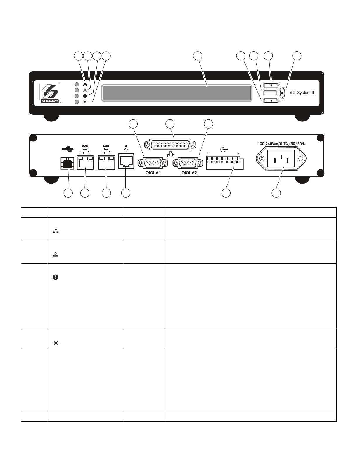
2.1 Controls and Indicators
Figure 2: Controls and Indicators
Table 7: SG-System II Front and Rear Panel Descriptions
Item No. Indicator/ Control/ Connector State/Pin Description
1 NETWORK Green LED ON
OFF
2 TROUBLE Orange LED ON
OFF
3 STATUS Yellow LED FLASHING
4 WATCHDOG Blue LED FLASHING
5 LCD Display 40x2 character LCD display.
6 DOWN Interface Button Scrolls down through menu options
OFF
STEADY
Network Absent
Network Present
Follows the network interface that receives T-Link signals.
Indicates any System Trouble not related to network or alarm (Note that the
LCD backlight will override the programmed colour and change to Yellow).
No System Trouble
Two flashes to indicate system busy out has occurred - caused by one of the
following conditions.
· On power up, the SG-System II clock is not set
· SG-System II firmware update (downloading)
· Either the printer or the computer buffer was full
· Checksum failed for any one of the flash ROM files
· Channel buffer corruption
· System In manual mode and option 042 is set to 4.
Normal Operation
Normal Operation (Software watchdog toggles every 200msec).
SG-System II Line Card Fault
Top line displays current Operating Mode.
Bottom line displays Trouble or received messages in Manual mode.
Alarm: If an alarm is present while the system is in Manual mode, the LCD
backlight will change to Red - overriding the programmed colour - and the
ACK button will flash. In addition, a buzzer will sound with each flash of the
ACK button.
Alarms received but not yet displayed are identified by a solid arrow symbol on
the far right edge of the LCD.
4

Table 7: SG-System II Front and Rear Panel Descriptions
Item No. Indicator/ Control/ Connector State/Pin Description
7 ACK Interface Button/LED FLASHING
OFF
Indicates unit is in Manual Mode and waiting for acknowledgement.
There are no alarm events requiring acknowledgement.
The ACK button is used to acknowledge an alarm event in Manual Mode. It
cannot acknowledge all alarms with one press, but must be pressed for each
individual alarm. The ACK button also acts as ENTER in Programming Mode.
8 UP Interface Button Scrolls up through menu options
9 ENTER Interface Button Selects a menu option
10 AUTOMATION Port (COM1) DB9 Sends automation messages to central station computer (e.g., Heartbeat if no
activity)
NOTE: Maximum Cable length is 1.8m (6ft). Longer cables may
impair performance. Use at own risk.
11 PARALLEL PRINTER Port DB25 (Female) Sends events to local printer (DB25 Female)
NOTE: Maximum Cable length is 1.8m (6ft). Longer cables may
impair performance. Use at own risk.
12 SERIAL PRINTER Port (COM2) DB9 RS232 Serial Printer Port. Sends events to local printer.
NOTE: Maximum Cable length is 1.8m (6ft). Longer cables may
impair performance. Use at own risk.
13 USB Port USB Type B USB Type B
NOTE: Maximum Cable length is 1.8m (6ft). Longer cables may
impair performance. Use at own risk.
14 WAN Interface Port CAT-5 Alarm port when system configured in dual NIC mode; Ethernet Cable (1.8m/
6ft)
NOTE: Longer cables may impair performance. Use at own risk
15 LAN Interface Port CAT-5 This interface is used for Console, Automation and Local (same subnet) T-Link
connections. Connects to LAN via CAT5 Ehernet Cable (1.8m/6ft)
NOTE: Longer cables may impair performance. Use at own risk.
16 DEBUG RJ-45 RJ-45 NOTE: Maximum Cable length is 1.8m (6ft). Longer cables may
impair performance. Use at own risk.
17 I/O Port ( Use AWG 18-22 wire) 1
10
11
12
13
2
3
4
5
6
7
8
9
Input
COM
Input
Input
COM
Input
Ouput
COM
Output
Output
COM
Output
Earth
UPS AC Failure (toggles from ground to open on failure)
Common (ground)
UPS DC Failure (toggles from ground to open on failure)
Remote ACK button - identical functionality to ACK button on LCD
Common (ground)
Future Use
Output 1 Follow Buzzer; Toggle to ground following the Buzzer
~ COMMON (ground)
Output 2 Toggle to ground following the CPM trouble LE
Output 3 Future Use
~ COMMON (ground)
Output 4 Future Use
~ EARTH GROUND
NOTE: Maximum Cable length is 1.8m (6ft). Longer cables may
impair performance. Use at own risk.
18 Mains Supply Connector 120/240VAC /0.7A/ 50-60Hz
Connection to Interruptible Power Supply (UPS recommended) with minimum
24 Hr standby capability required.
Refer to Section 2.2. Setup & Testing
For ULC Installations, the equipment shall be rack mounted and energized by a permanently wired supply in accordance with C22.1, Canadian
Electrical Code, Part 1, Safety Standard for Electrical Installations, section 32.
NOTE: The LED indicators and the LCD can be tested for integrity by accessing the following in the main programmingmenu: item 3 - System Functions > item 5 - Visual Indicators Test.
5
2.2 Set Up and Testing
NOTES:
Install External Devices connected to item (10)-(17) in the same room as the
SG-System II.
Maintain 1/4” (6.5mm) separation between power limited and non-power limited
circuits. Use power limited, supervised circuits only/
I/O Terminal is Open collector 20mA switched to ground. Wire with 18-22 AWG.
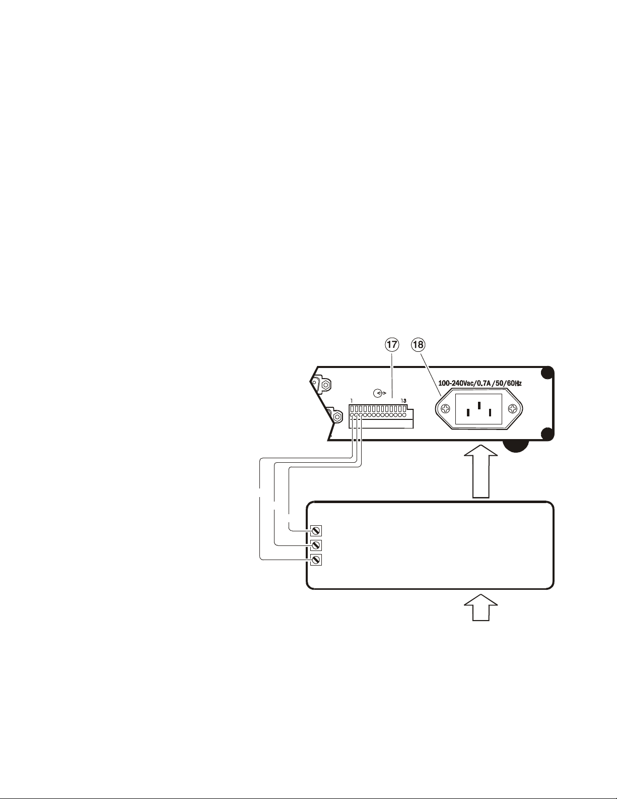
AC In
UPS
UPS Low Bat (normally closed)
UPS AC Trouble (normally closed
To SG-System II I/O
From AC Mai ns
I/O Open Collector, 20 mA (Max)
Use 18-22 AWG (0.5 - 1.0mm) wiring
To SG-System II
IEC grounded receptacle
Pin 1
Pin 2
Pin 3
DSC recommends testing the receiver before actual installation. Becoming familiar with the connections and setup of the unit on the workbench
will make final installation simpler.
The following items are required:
• IEC Power Supply cord
• CAT5 Ethernet Cable
• One or more T-Link modules
• Hub/router or network connection
NOTE: When a Hub or Router/Gateway is used with the SG-System II, 24 Hr Standby Power is required for these
devices (i.e., UL Listed UPS, Battery Backup, or engine driven generator).
1. Unpack the SG-System II components.
NOTE: Carefully unpack the receiver and inspect for shipping damage. If there is any apparent damage, notify the
carrier immediately.
2. Install the rack-mount brackets or the rubber feet in the indents as required.
3. Connect a CAT5 Cable (not supplied) .
4. Connect the main power using a standard computer IEC cable (not supplied).
Figure 3: Wiring Diagram
WARNING:
To reduce the risk of electrical shock, the
SG-System II is equipped with a grounding type
power supply IEC receptacle.
Connect SG-System II using an appropriate IEC
cable to a grounded receptacle.
Connect SG-System II to UPS dry contact connections only.
Do NOT connect to a receptacle contrrolled by a
switch.
NOTES:
For UL Installations
Mains Supply: 120VAC/60Hz
UPS Output Rating: 120VAC/60Hz, 2.5A. Use UL
listed UPS (uninterrupted power supply) for protective-signalling systems and listed burglar alarm
power supply as applicable.
For CE Installations
Mains Supply: 240VAC/50Hz
UPS Output Rating (non UL): 240VAC 50Hz
5. The LCD will power up and display internal troubles (printer, computer).
NOTE: Internal diagnostics may require more than one minute during the power up sequence.
6. Send a signal from a control panel to the receiver. The signal will be displayed on the LCD. Press the ACK button to silence the buzzer and
clear the signal from the LCD.
AC Out
Common
6
 Loading...