

Sur-Gard MLR2000 Installation Manual

Sur-Gard MLR2000
Virtual Network Receiver
Installation
WARNING: This manual contains information on limitations regarding
product use and function and information on the limitations as to
liability of the manufacturer. The entire manual should be carefully read.
Manual
version 1.5
FCC Compliance Statement
CAUTION: Changes or modifications not expressly approved by Digital Security Controls could void
your authority to use this equipment.
This equipment has been tested and found to comply with the limits for a Class B digital device, pursuant to Part 15 of the FCC Rules. These limits are designed to provide reasonable protection against
harmful interference in a residential installation. This equipment generates, uses and can radiate radio
frequency energy and, if not installed and used in accordance with the instructions, may cause harmful interference to radio communications. However, there is no guarantee that interference will not
occur in a particular installation. If this equipment does cause harmful interference to radio or television reception, which can be determined by turning the equipment off and on, the user is encouraged
to try to correct the interference by one or more of the following measures:
Re-orient the receiving antenna.
Increase the separation between the equipment and receiver.
Connect the equipment into an outlet on a circuit different from that to which the receiver is connected.
Consult the dealer or an experienced radio/television technician for help.
The user may find the following booklet prepared by the FCC useful: “How to Identify and Resolve
Radio/Television Interference Problems”. This booklet is available from the U.S. Government Printing Office, Washington D.C. 20402, Stock # 004-000-00345-4.
IMPORTANT INFORMATION
This equipment complies with Part 68 of the FCC Rules. On the side of this equipment is a label that
contains, among other information, the FCC registration number and ringer equivalence number
(REN) for this equipment. If requested, this number must be provided to the Telephone Company.
FCC Registration Number: 1VDCAN-25404-AL-N
REN: 0.2B
USOC Jack: RJ11C
Telephone Connection Requirements
A plug and jack used to connect this equipment to the premises wiring and telephone network must
comply with the applicable FCC Part 68 rules and requirements adopted by the ACTA. A compliant
telephone cord and modular plug is provided with this product. It is designed to be connected to a
compatible modular jack that is also compliant. See installation instructions for details.
Ringer Equivalence Number (REN) The REN is used to determine the number of devices that may
be connected to a telephone line. Excessive RENs on a telephone line may result in the devices not
ringing in response to an incoming call. In most but not all areas, the sum of RENs should not exceed
five (5.0). To be certain of the number of devices that may be connected to a line, as determined by the
total RENs, contact the local Telephone Company. For products approved after July 23, 2001, the
REN for this product is part of the product identifier that has the format
US: AAAEQ##TXXXX. The digits represented by ## are the REN without a decimal point (e.g., 03
is a REN of 0.3). For earlier products, the REN is separately shown on the label.
Incidence of Harm If this equipment Sur-Gard MLR2000 causes harm to the telephone network, the
telephone company will notify you in advance that temporary discontinuance of service may be
required. But if advance notice is not practical, the Telephone Company will notify the customer as
soon as possible. Also, you will be advised of your right to file a complaint with the FCC if you
believe it is necessary.
Changes in Telephone Company Equipment or Facilities The Telephone Company may make
changes in its facilities, equipment, operations or procedures that could affect the operation of the
equipment. If this happens the Telephone Company will provide advance notice in order for you to
make necessary modifications to maintain uninterrupted service.
Equipment Maintenance Facility If trouble is experienced with this equipment Sur-Gard
MLR2000, for repair or warranty information, please contact the facility indicated below. If the
equipment is causing harm to the telephone network, the Telephone Company may request that you
disconnect the equipment until the problem is solved. This equipment is of a type that is not intended
to be repaired by the end user.
Simplex Time Recorder Co. 100 Simplex Drive, Westminster MA 01441-0001 USA, Tel: (978) 7312500
Additional Information Connection to party line service is subject to state tariffs. Contact the state
public utility commission, public service commission or corporation commission for information.
If your home has specially wired alarm equipment connected to the telephone line, ensure the installation of this equipment Sur-Gard MLR2000 does not disable your alarm equipment. If you have questions about what will disable alarm equipment, consult your telephone company or a qualified
installer.
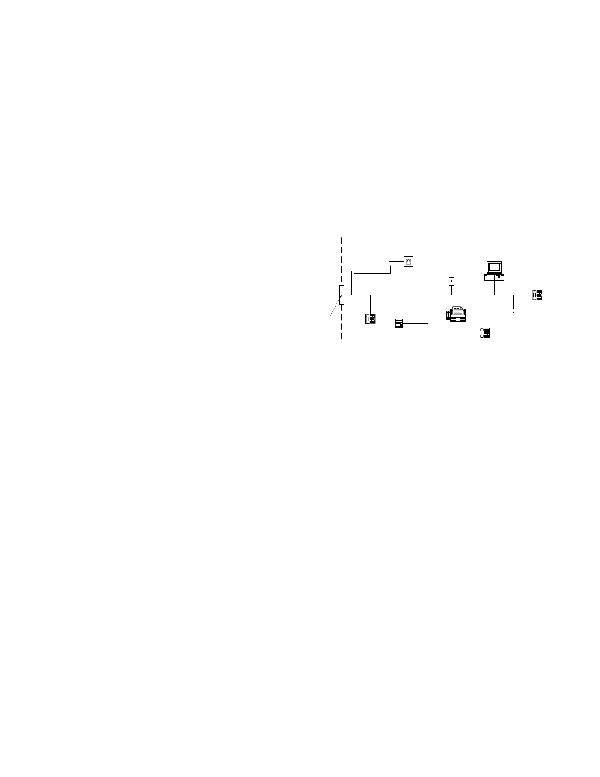
Network
Service
Provider's
Facilities
Telephone
Network
Demarcation
Point
Customer Premises Equipment and Wiring
RJ-31X
Jack
Alarm Dialing
Equipment
Line
Telephone
Answering
System
Unused
RJ-11 Jack
Fax Machine
Telephone
Computer
Unused
RJ-11 Jack
Telephon
Industry Canada Statement
IC: 160A-MLR2000
NOTICE: This equipment meets the applicable Industry Canada Terminal Equipment
Technical Specifications. This is confirmed by the registration number. The abbreviation,
IC, before the registration number signifies that registration was performed based on a
Declaration of Conformity indicating that Industry Canada technical specifications were
met. It does not imply that Industry Canada approved the equipment.
NOTICE: The Ringer Equivalence Number (REN) for this terminal is 01. The REN
assigned to each terminal equipment provides an indication of the maximum number of
terminals allowed to be connected to a telephone interface. The termination on an interface may consist of any combination of devices subject only to the requirement that the
sum of the Ringer Equivalence Numbers of all the devices does not exceed five.

Table of Contents
Section 1 - Introduction ............................................. 1
1.1 CPM2000 ................................................................ 1
1.2 DRL2000 ................................................................. 1
1.3 Power and Supervision............................................. 1
1.4 CPM2000 Outputs/ Inputs ....................................... 1
1.5 System Overview...................................................... 2
1.6 Virtual Receiver Architecture .................................... 2
1.7 Number of Line Cards Supported............................. 2
1.8 Redundancy............................................................. 2
1.9 Approvals ................................................................ 2
1.10 Virtual Connectivity ................................................. 2
1.11 Internal 10B2 Ethernet............................................. 2
Section 2 - Quick Start ............................................... 3
2.1 Receiver Setup and Operation.................................. 3
2.2 Bench Testing .......................................................... 9
Section 3 - Installation............................................. 10
3.1 Dimensions............................................................ 10
3.2 Definity DNIS ......................................................... 10
3.3 Mounting the Receiver........................................... 10
3.4 Printer Connections ............................................... 10
3.5 Computer Connections.......................................... 10
3.6 Telephone Line Connections .................................. 10
3.7 Grounding............................................................. 10
3.8 Power Supply......................................................... 10
3.9 Battery Charging Current....................................... 10
3.10 Removing and Installing System Components ........ 10
3.11 To Install a Line Card Module ................................. 10
Section 4 - DRL2000 Digital Receiver Line Card .... 11
4.1 General Information............................................... 11
4.2 DRL2000 Features.................................................. 11
4.3 Installation............................................................. 11
4.4 DRL2000 Controls.................................................. 11
Section 5 - DRL2000 Operating Mode ..................... 12
5.1 DRL2000 Standby Mode ........................................ 12
5.2 DRL2000 Cold Start-up.......................................... 12
5.3 Communications in Progress.................................. 12
Section 6 - Advanced Programming ...................... 13
6.1 Profile Introduction ................................................ 13
6.2 A.H.S. (Automatic Handshake Selection) ................ 14
6.3 Dynamic Options: [30] - [FF]............................... 17
Section 7 - DRL2000 Communication Formats ....... 24
7.1 Common Formats.................................................. 24
7.2 Sur-Gard DTMF Formats......................................... 24
7.3 Acron Format......................................................... 24
7.4 Ademco Contact ID................................................24
7.5 Ademco Express .....................................................26
7.6 Ademco Super Fast (High Speed Format) ................26
7.7 FBI Super Fast Format.............................................26
7.8 ITI Format...............................................................26
7.9 ITI Sensor Library ....................................................26
7.10 Modem II, Modem IIE, Modem IIIa² and
BFSK Formats .........................................................27
7.11 SIA FSK ..................................................................27
7.12 Silent Knight FSK1, FSK2 ........................................27
7.13 Silent Knight FSK2 Protocol ....................................27
7.14 Sescoa Super Speed ...............................................28
7.15 DRL2000 Predefined Library Decoding and Event
Codes Table27
Section 8 - CPM2000 Central Processing Module... 30
8.1 General Information ...............................................30
8.2 Features .................................................................30
8.3 CPM2000 Controls.................................................30
Section 9 - CPM2000 Wiring Diagram ..................... 31
9.1 Loss of Socket/Automation.....................................31
9.2 CPM Redundancy...................................................31
9.3 CPM Restoral .........................................................31
Section 10 - MLR2000 Computer Interface............. 32
10.1 Virtual connectivity.................................................32
10.2 Automation Mode..................................................32
10.3 TCP/IP Ports............................................................32
10.4 Client Side Connects ..............................................32
10.5 Stream Packet Structure .........................................32
10.6 Status Addressing...................................................32
10.7 Overview of Communication ..................................32
10.8 Console spcifies which SG Automation to
Supervise................................................................33
Section 11 - PSU2000 Power supply Module .......... 36
Section 12 - Automation Protocols ......................... 37
12.1 Data Byte protocol..................................................37
12.2 Acknowledgment of the Signal ..............................37
Section 13 - Detailed Description of Computers ... 38
13.1 COM Responses .....................................................38
13.2 Automation Absent...............................................38
Appendix A - DRL2000 Communication Formats...........39
Appendix B - Decimal - HEX - Binary Conversion Chart.40
Appendix C - ASCII Character Chart ..............................41
Appendix D - Printer Words: Options [60-6F]................42
Appendix E - Panels Compatibility List ..........................44

WARNING Please Read Carefully
Note to Installers
This warning contains vital information. As the only individual in contact with system users, it is your
responsibility to bring each item in this warning to the attention of the users of this system.
System Failures
This system has been carefully designed to be as effective as possible. There are circumstances, however,
involving fire, burglary, or other types of emergencies where it may not provide protection. Any alarm
system of any type may be compromised deliberately or may fail to operate as expected for a variety of
reasons. Some but not all of these reasons may be:
■ Inadequate Installation
A security system must be installed properly in order to provide adequate protection. Every installation
should be evaluated by a security professional to ensure that all access points and areas are covered. Locks
and latches on windows and doors must be secure and operate as intended. Windows, doors, walls, ceilings and other building materials must be of sufficient strength and construction to provide the level of
protection expected. A reevaluation must be done during and after any construction activity. An evaluation by the fire and/or police department is highly recommended if this service is available.
■ Criminal Knowledge
This system contains security features which were known to be effective at the time of manufacture. It is
possible for persons with criminal intent to develop techniques which reduce the effectiveness of these
features. It is important that a security system be reviewed periodically to ensure that its features remain
effective and that it be updated or replaced if it is found that it does not provide the protection expected.
■ Access by Intruders
Intruders may enter through an unprotected access point, circumvent a sensing device, evade detection by
moving through an area of insufficient coverage, disconnect a warning device, or interfere with or prevent
the proper operation of the system.
■ Power Failure
Control units, intrusion detectors, smoke detectors and many other security devices require an adequate
power supply for proper operation. If a device operates from batteries, it is possible for the batteries to
fail. Even if the batteries have not failed, they must be charged, in good condition and installed correctly.
If a device operates only by AC power, any interruption, however brief, will render that device inoperative
while it does not have power. Power interruptions of any length are often accompanied by voltage fluctuations which may damage electronic equipment such as a security system. After a power interruption has
occurred, immediately conduct a complete system test to ensure that the system operates as intended.
■ Failure of Replaceable Batteries
This system’s wireless transmitters have been designed to provide several years of battery life under normal conditions. The expected battery life is a function of the device environment, usage and type. Ambient conditions such as high humidity, high or low temperatures, or large temperature fluctuations may
reduce the expected battery life. While each transmitting device has a low battery monitor which identifies when the batteries need to be replaced, this monitor may fail to operate as expected. Regular testing
and maintenance will keep the system in good operating condition.
■ Compromise of Radio Frequency (Wireless) Devices
Signals may not reach the receiver under all circumstances which could include metal objects placed on or
near the radio path or deliberate jamming or other inadvertent radio signal interference.
■ System Users
A user may not be able to operate a panic or emergency switch possibly due to permanent or temporary
physical disability, inability to reach the device in time, or unfamiliarity with the correct operation. It is
important that all system users be trained in the correct operation of the alarm system and that they know
how to respond when the system indicates an alarm.
■ Smoke Detectors
Smoke detectors that are a part of this system may not properly alert occupants of a fire for a number of
reasons, some of which follow. The smoke detectors may have been improperly installed or positioned.
Smoke may not be able to reach the smoke detectors, such as when the fire is in a chimney, walls or roofs,
or on the other side of closed doors. Smoke detectors may not detect smoke from fires on another level of
the residence or building.
Every fire is different in the amount of smoke produced and the rate of burning. Smoke detectors cannot
sense all types of fires equally well. Smoke detectors may not provide timely warning of fires caused by
carelessness or safety hazards such as smoking in bed, violent explosions, escaping gas, improper storage
of flammable materials, overloaded electrical circuits, children playing with matches or arson.
Even if the smoke detector operates as intended, there may be circumstances when there is insufficient
warning to allow all occupants to escape in time to avoid injury or death.
■ Motion Detectors
Motion detectors can only detect motion within the designated areas as shown in their respective installation instructions. They cannot discriminate between intruders and intended occupants. Motion detectors
do not provide volumetric area protection. They have multiple beams of detection and motion can only be
detected in unobstructed areas covered by these beams. They cannot detect motion which occurs behind
walls, ceilings, floor, closed doors, glass partitions, glass doors or windows. Any type of tampering
whether intentional or unintentional such as masking, painting, or spraying of any material on the lenses,
mirrors, windows or any other part of the detection system will impair its proper operation.
Passive infrared motion detectors operate by sensing changes in temperature. However their effectiveness
can be reduced when the ambient temperature rises near or above body temperature or if there are intentional or unintentional sources of heat in or near the detection area. Some of these heat sources could be
heaters, radiators, stoves, barbeques, fireplaces, sunlight, steam vents, lighting and so on.
■ Warning Devices
Warning devices such as sirens, bells, horns, or strobes may not warn people or waken someone sleeping
if there is an intervening wall or door. If warning devices are located on a different level of the residence
or premise, then it is less likely that the occupants will be alerted or awakened. Audible warning devices
may be interfered with by other noise sources such as stereos, radios, televisions, air conditioners or other
appliances, or passing traffic. Audible warning devices, however loud, may not be heard by a hearingimpaired person.
■ Telephone Lines
If telephone lines are used to transmit alarms, they may be out of service or busy for certain periods of
time. Also an intruder may cut the telephone line or defeat its operation by more sophisticated means
which may be difficult to detect.
■ Insufficient Time
There may be circumstances when the system will operate as intended, yet the occupants will not be protected from the emergency due to their inability to respond to the warnings in a timely manner. If the system is monitored, the response may not occur in time to protect the occupants or their belongings.
■ Component Failure
Although every effort has been made to make this system as reliable as possible, the system may fail to
function as intended due to the failure of a component.
■ Inadequate Testing
Most problems that would prevent an alarm system from operating as intended can be found by regular
testing and maintenance. The complete system should be tested weekly and immediately after a break-in,
an attempted break-in, a fire, a storm, an earthquake, an accident, or any kind of construction activity
inside or outside the premises. The testing should include all sensing devices, keypads, consoles, alarm
indicating devices and any other operational devices that are part of the system.
■ Security and Insurance
Regardless of its capabilities, an alarm system is not a substitute for property or life insurance. An alarm
system also is not a substitute for property owners, renters, or other occupants to act prudently to prevent
or minimize the harmful effects of an emergency situation.
Limited Warranty
Digital Security Controls warrants the original purchaser that for a period of twelve months from the date
of purchase, the product shall be free of defects in materials and workmanship under normal use. During
the warranty period, Digital Security Controls shall, at its option, repair or replace any defective product
upon return of the product to its factory, at no charge for labour and materials. Any replacement and/or
repaired parts are warranted for the remainder of the original warranty or ninety (90) days, whichever is
longer. The original purchaser must promptly notify Digital Security Controls in writing that there is
defect in material or workmanship, such written notice to be received in all events prior to expiration of
the warranty period.
as a user license under the terms of the software license agreement included with the product. The
Customer assumes all responsibility for the proper selection, installation, operation and maintenance of any products purchased from DSC. Custom products are only warranted to the extent that
they do not function upon delivery. In such cases, DSC can replace or credit at its option.
International Warranty
The warranty for international customers is the same as for any customer within Canada and the United
States, with the exception that Digital Security Controls shall not be responsible for any customs fees,
taxes, or VAT that may be due.
Warranty Procedure
To obtain service under this warranty, please return the item(s) in question to the point of purchase. All
authorized distributors and dealers have a warranty program. Anyone returning goods to Digital Security
Controls must first obtain an authorization number. Digital Security Controls will not accept any shipment
whatsoever for which prior authorization has not been obtained.
Conditions to Void Warranty
This warranty applies only to defects in parts and workmanship relating to normal use. It does not cover:
• damage incurred in shipping or handling;
• damage caused by disaster such as fire, flood, wind, earthquake or lightning;
• damage due to causes beyond the control of Digital Security Controls such as excessive voltage,
mechanical shock or water damage;
• damage caused by unauthorized attachment, alterations, modifications or foreign objects;
• damage caused by peripherals (unless such peripherals were supplied by Digital Security Controls);
• defects caused by failure to provide a suitable installation environment for the products;
• damage caused by use of the products for purposes other than those for which it was designed;
• damage from improper maintenance;
• damage arising out of any other abuse, mishandling or improper application of the products.
Items Not Covered by Warranty
In addition to the items which void the Warranty, the following items shall not be covered by Warranty: (i)
freight cost to the repair centre; (ii) products which are not identified with DSC's product label and lot
number or serial number; (iii) products disassembled or repaired in such a manner as to adversely affect
performance or prevent adequate inspection or testing to verify any warranty claim. Access cards or tags
returned for replacement under warranty will be credited or replaced at DSC's option. Products not covered by this warranty, or otherwise out of warranty due to age, misuse, or damage shall be evaluated, and
a repair estimate shall be provided. No repair work will be performed until a valid purchase order is
received from the Customer and a Return Merchandise Authorisation number (RMA) is issued by DSC's
Customer Service.
Digital Security Controls’s liability for failure to repair the product under this warranty after a reasonable
number of attempts will be limited to a replacement of the product, as the exclusive remedy for breach of
warranty. Under no circumstances shall Digital Security Controls be liable for any special, incidental, or
consequential damages based upon breach of warranty, breach of contract, negligence, strict liability, or
any other legal theory. Such damages include, but are not limited to, loss of profits, loss of the product or
any associated equipment, cost of capital, cost of substitute or replacement equipment, facilities or services, down time, purchaser’s time, the claims of third parties, including customers, and injury to prop-
The laws of some jurisdictions limit or do not allow the disclaimer of consequential damages.
erty.
If the laws of such a jurisdiction apply to any claim by or against DSC, the limitations and disclaimers contained here shall be to the greatest extent permitted by law. Some states do not allow
the exclusion or limitation of incidental or consequential damages, so that the above may not
apply to you.
Disclaimer of Warranties
This warranty contains the entire warranty and shall be in lieu of any and all other warranties,
whether expressed or implied (including all implied warranties of merchantability or fitness for a particular purpose) And of all other obligations or liabilities on the part of Digital Security Controls Digital Security Controls neither assumes responsibility for, nor authorizes any other person purporting to
act on its behalf to modify or to change this warranty, nor to assume for it any other warranty or liability concerning this product.
This disclaimer of warranties and limited warranty are governed by the laws of the province of Ontario,
Canada.
WARNING: Digital Security Controls recommends that the entire system be completely tested on a
regular basis. However, despite frequent testing, and due to, but not limited to, criminal tampering
or electrical disruption, it is possible for this product to fail to perform as expected.
Installer’s Lockout
Any products returned to DSC which have the Installer’s Lockout option enabled and exhibit no other
problems will be subject to a service charge.
Out of Warranty Repairs
Digital Security Controls will at its option repair or replace out-of-warranty products which are returned
to its factory according to the following conditions. Anyone returning goods to Digital Security Controls
must first obtain an authorization number. Digital Security Controls will not accept any shipment whatsoever for which prior authorization has not been obtained.
Products which Digital Security Controls determines to be repairable will be repaired and returned. A set
fee which Digital Security Controls has predetermined and which may be revised from time to time, will
be charged for each unit repaired.
Products which Digital Security Controls determines not to be repairable will be replaced by the nearest
equivalent product available at that time. The current market price of the replacement product will be
charged for each replacement unit.
There is absolutely no warranty on software and all software products are sold

Section 1 - Introduction
The MLR2000 is a Multi-Line, Multi-Format Digital Receiver for
commercial fire and burglary. The basic unit consists of 60 individual line-cards (DRL2000) connected to a dual redundant central resource, router and protocol converter (CPM2000). The
MLR2000 includes many features, especially high bandwidth
internal buses and high bandwidth external connections to
allow traditional network philosophies to be observed for the
first time on a central station receiver. The MLR2000 can
decode a variety of popular and widely used communication
formats. Refer to Appendix A, DRL2000 Communication Formats for a list of the available communication protocols.
The MLR2000's real-time clock and calendar 'stamps' all information received with the time and date, and all information
may be printed or forwarded to a computer. To ensure security,
adjustment of the clock, calendar and other programming is
protected by password codes.
1.1 CPM2000
The CPM2000 Central Processing Module oversees operation of the receivers. Along with its built-in keypad and
LCD message screen, the CPM2000 features TCP/IP, two
parallel printers, one serial printer and two serial computer
interface capability.
1.2 DRL2000
Each DRL2000 module can monitor two telephone lines.
The line card module is equipped with a 256-event nonvolatile memory buffer to record events and corresponding telephone numbers. Caller Source capability is built-in
and telephone numbers can be printed out, sent to automation and stored in memory. Events and information
stored in memory can be printed at any time. Each line
card also features flash EPROM uploads through the
Debug port for software upgrades or options programming.
1.3 Power and Supervision
1.3.1 Power
The MLR2000 power supplies inputs are 120 Vac at 10A,
60 Hz. Each AC power supply supplies a nominal 28 Vdc
+/-5% power. The receiver is equipped with 24V
rechargeable stand-by battery connections at 160 Ahr.
and an automatic battery charger. Provision is made for an
internal battery pack for temporary use. User supplied
batteries may be used externally but must be fused and
connected to 10-32 lugs supplied via a stud termination.
Full power operation is .5 Amps per line and 1 Amp per
CPM at 28 Vdc nominal. All elements have extensive
power down capabilities and are implemented in CMOS
logic.
1.3.2 Supervision
The stand-by battery voltage and connections are supervised. The Line Cards are also continuously supervised to
ensure uninterrupted communication with the CPM2000.
Any trouble conditions are reported on the LCD screens
and sent to the printer and the computer.
The DRL2000 Line Card Module also verifies communications with the CPM2000. In the event of a malfunction,
the operator will be advised with a visual indication and
the Line Cards will continue to function. Each line card will
continue to receive information.
The printer is supervised for off-line, paper out and other
trouble conditions. The communication link to the computer through the RS232 ports is monitored by the supervisory 'heartbeat' test transmissions.
1.3.3 Compatibility
Central station automation software packages such as:
• MAS • DICE • SIMS II • GENESYS • S.I.S. • IBS
•MicroKey
support the MLR2000 Sur-Gard interface.
Refer to automation software specifications for compatibility.
NOTES: Automation connections are considered
supplementary per UL864 Listing. Compatibility
with the automation software in a system used at a
central station is intended to be handled under a
separate UL1981 software and/or site certification
evaluation.
1.4 CPM2000 Outputs/ Inputs
• The CPM2000 features four switched-negative
(PGMOUT1 is activated when automation fails) outputs,
two relay outputs and four inputs.
1.5 System Overview
• Patented Caller Identification (Call Display) capability
• Patent Pending DNIS Identification
• nonvolatile RAM on each DRL2000 line card module for
programming and event buffer.
• Fast Ethernet communication between line-cards and
CPM
• Flash download for software upgrades
• Up to 64 different options set (profiles per line)
• Patented virtual configurations
• 3/1, 4/2 formats with or without parity, 4/1 without parity at 10, 14, 20, or 40 baud
• 4/1, 4/2, 4/3, and 4/3 DTMF formats
• Optional* formats: 3-2, 4/1, 4/2 extended
• ACRON DTMF format
• Contact ID (DTMF) format
• Adcor 20 baud
• Super fast or high speed DTMF format, with or without
parity
• DTMF 4/1 express format (optional)
• DTMF 4/2 express format
• FBI super fast format with or without parity
• Radionics Modem II, Modem IIE, Modem IIIa2 and BFSK
formats
• SIA format: 110 and 300 baud, tone and data acknowledgement
• SK FSK0, FSK1, FSK2
• Any handshake frequencies by increment of 100 Hz
from 100 Hz to 2300 HZ, Dual Tone, SIA FSK, Modem II
and ITI selected by configuration commands
• Up to 8 different handshakes per profile.
• Large, easy to read 2-line, 16-characters-per-line, LCD
(Liquid Crystal Display) screen
• All modules function individually to help ensure uninterrupted operation during hardware or software upgrades
• Inputs on CPM2000 for UPS supervisory
• 255 lines maximum per receiver
• 256-event memory buffer on each individual line card
•Real-time clock
• CPM2000 features 32-bit micro-controller
• Two parallel printer port; three serial RS232 ports and
one 10 BaseT connection.
• Programmable serial ports configuration
• Programmable System Functions: Computer and printer
• Fast transmission of multiple alarms to the computer
and printer to ensure operator's quick response
*All formats noted as optional are selected using configuration commands.
1

• Continuous verification of the computer-receiver links
with the 'heartbeat' function
• Switched-negative outputs on CPM2000 (special applications)
• AC-lost detection and stand-by battery supervision
• Low battery detection and automatic low battery disconnect to prevent deep-discharge damage to battery
• Operator Acknowledge
• Telephone Line Supervision
1.6 Virtual Receiver Architecture
The most novel feature of the DRL2000 is the ability to
use Telco information delivered as a DNIS (dialed number
identification service) to allow the Sur-Gard expert format
identification system to option on the fly each received call
to eliminate dedicated line pool hardware. Instead the
DNIS allows call up options which set up virtual line pools
to identify security formats and extend account numbers.
Standard dialed number identification is supported up to
10 digits.
Each dialed number should be assigned to a virtual
receiver. Each dialed number would have formerly been a
line pool on conventional line-cards.
1.7 Number of Line Cards Supported
The system will support a maximum of 255 line-cards concurrently connected. Optional hubs will be required for
backplane connectivity in installations beyond 5 shelves.
1.8 Redundancy
The MLR2000 has a main power supply module for side A
and for side B, and an optional stand-by power supply per
rack. Additional 10B2 Ethernet is available as a backup B
side. This and the ability to mount an optional second
CPM2000 controller will allow for seamless system redundancy in maximum configuration. In practical terms this
means that any line card may fail and not affect system
performance ; and with redundant CPM's the B unit will
take up where the A unit failed with a loss of no more
than 30 seconds. External networking components would
necessarily be duplicated to take full advantage of this
configuration.
1.9 Approvals
1.9.1 Industry Approvals
The MLR2000 in redundant configuration is listed under
the following UL standards:
• UL 864 Control Units for Fire-Protective Signaling Systems
• UL 1610 Central Station Burglar Alarm Units
This equipment should be installed in accordance
with the requirements of NFPA72, NFPA70 and
UL827.
1.9.2 System Connectivity
The system may have two identical CPMs both connected
to internal resources. Internal connections are A and B
side 28 V power and A and B side 10B2 Ethernet. Additional internal connections are power monitoring services
on the primary rack. External connections are two parallel
printer and three serial ports. The serial ports are intended
primarily for debug applications but may be used for fallback automation outputs (optional). The primary automation connection is via 10BT Ethernet connection. Again if
redundant CPM's are used the external network components must be duplicated to allow for full redundancy.
1.9.3 Automation Mode
In automation mode it is expected that the primary connection is via TCP/IP networking on the 10BT Ethernet
connection. A menu on the CPM2000 will prompt the
user for the IP address setup and port setup. Once the
configuration management port is set up, all other
options and setups may be done via a Telnet session or
the Sur-Gard Console.
1.9.4 UL Manual Mode
For UL manual mode, each event will activate the internal
buzzer to be acknowledged manually. Each event will be
sent automatically to all connected printers.
NOTE: For central station applications the signaling
performance of each dact shall be manually tracked.
Failure to receive a signal from a dact over a 24-hour
period shall be handled as a trouble signal.
1.10 Virtual Connectivity
Each receiver has one IP address and a number of associated ports. Internal socket programming uses specific
ports for expected tasks. The MLR2000 is the listener.
1.10.1 Configuration Management - Sur-Gard Configuration Port 1024
A tool is provided for NT 4 + or Windows 9x/2000/XP
environments which provides graphical style menu for
configuration management. Additional features are storage of virtual receiver setups, formats conversion table
and configuration wizards.
1.10.2 Status Addressing
Line card status will be reported via physical addressing.
This will be assigned by shelf and slot number. All device
status information is in Sur-Gard format. The reporting of
status on this port, automation output and printer will
relate to physical addressing.
1.10.3 Automation input/output (Port 1025, 1026)
Traditional automation communication will be provided
via a minimum of two ports. The primary port is Sur-Gard
standard output and provides Sur-Gard standard automation output.
Optional secondary automation communication will be
provided to map to proprietary types. It is expected that
named virtual receiver types will be mapped to this output. In addition two way automation commands may be
supported on this port.
1.11 Internal 10B2 Ethernet
Internal Ethernet is not standard TCP/IP instead it has allocated proprietary type per Internet standards. Full physical
10B2 requirements are met allowing approved segment
interconnects to be used including hubs, optical transceivers and wan interconnects (wan interconnects preclude
trap and capture commands).
2
Section 2 - Quick Start
2.1 Receiver Setup and Operation
2.1.1 Unpacking
Carefully unpack the receiver and inspect for shipping
damage. If there is any apparent damage, notify the carrier immediately.
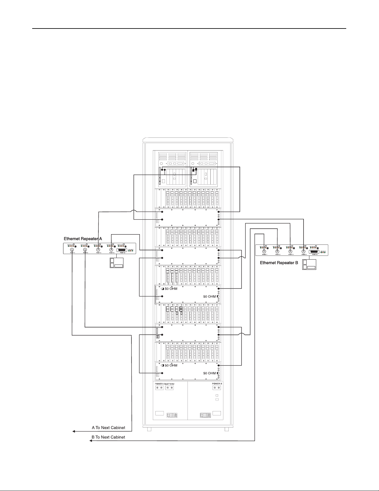
2.1.2 Ethernet Connections
NOTES: Be sure to be properly grounded.
• Take a 50 ohm coaxial cable and connect one end to the
BNC connector (ETHERNET A) of the CPM2000. The
other end of the coaxial cable should be connected to
the BNC connector (ENET A IN) of the backplane.
Figure 1, 60 Line Cards Configuration
• Take a 50-ohm coaxial cable and connect one end to
the BNC connector (ETHERNET B) of the CPM2000. The
other end of the coaxial cable should be connected to
the BNC connector (ENET B IN) of the backplane.
• Make sure that there are 50 ohm BNC terminators on
the other end of the T Connectors of the CPM2000
labelled ETHERNET A AND B.
• Make sure that there are 50 ohm BNC terminators connected on the BNC terminals marked ENET A OUT and
ENET B OUT of the backplane. (This should be already
done.)
3
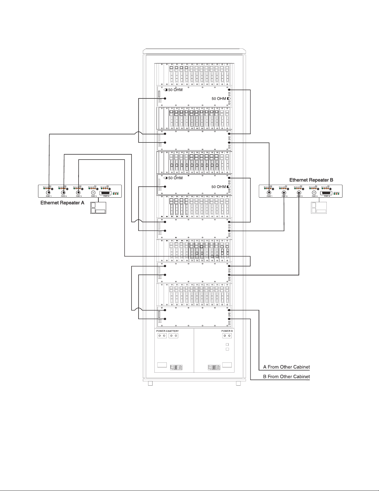
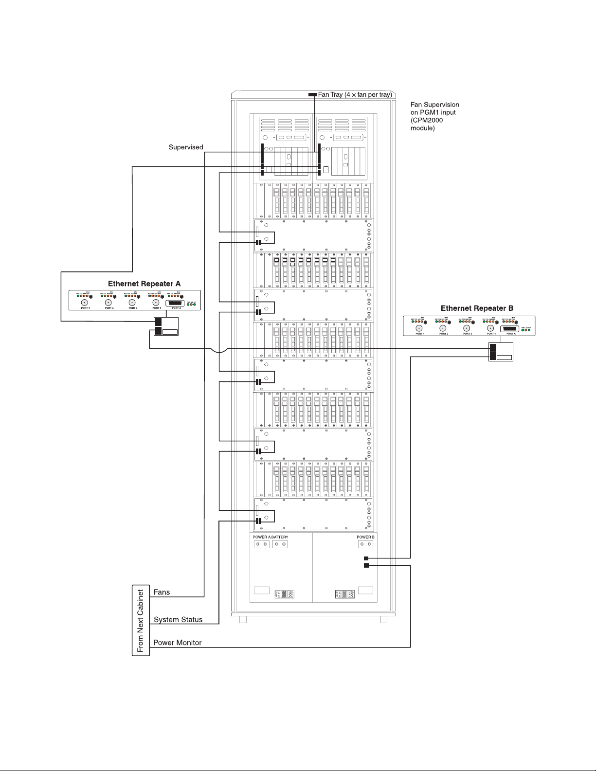
Figure 2, 72 Line Cards Configuration (Expansion cabinet)
4
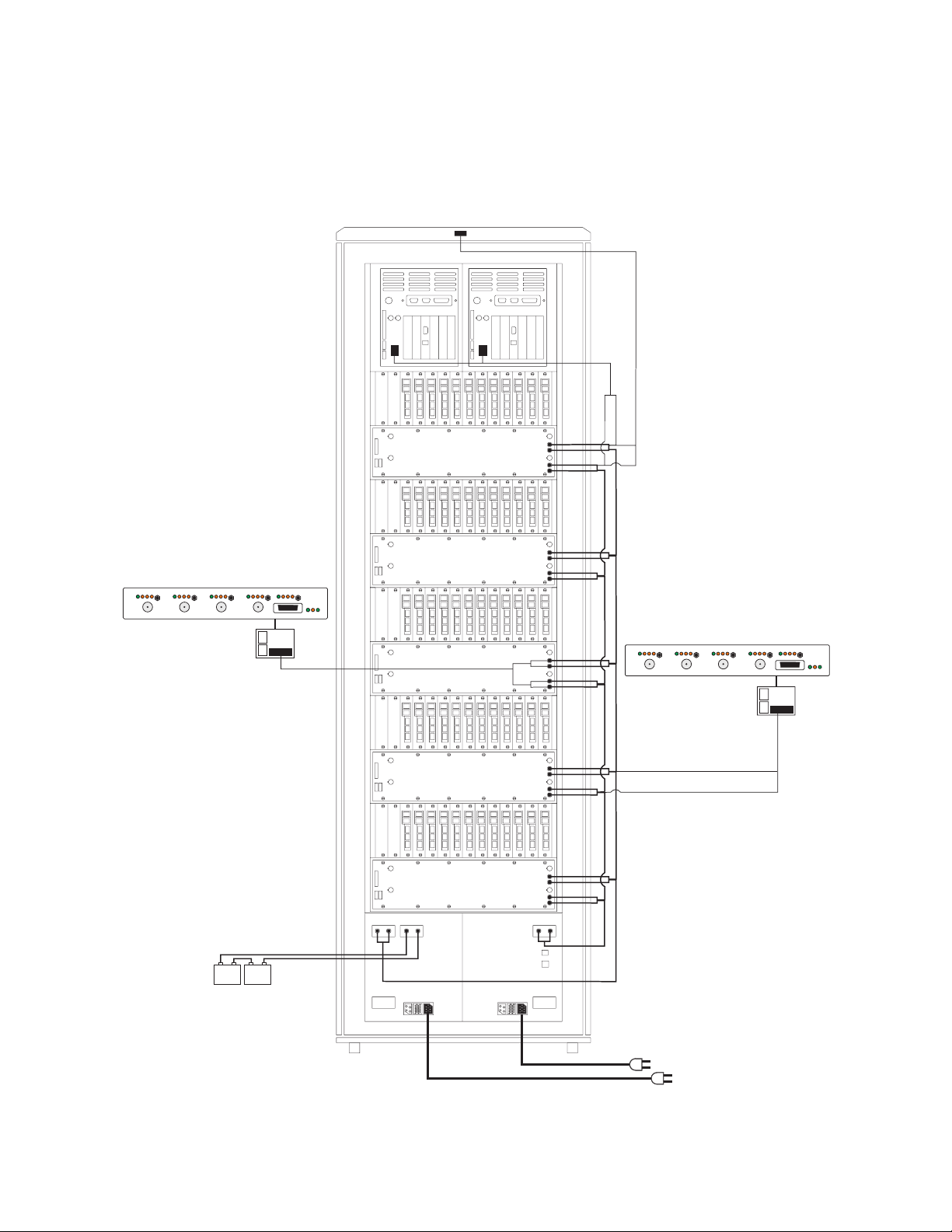
2.1.3 Power Cable Connections
Ethernet Repeater B
Ethernet Repeater A
• Take the power cable for the CPM2000 and connect the
labelled wire to the designated terminal on the backplane. Take the other end of the power cable and connect it to the power connector on the CPM2000.
Figure 3, 60 Line Cards Configuration
Fan Tray
• Take the power cables (10 gage) and connect one end
to the power terminals of the backplane marked PWRGND (black cable) and +28 V
other end of the power cables and connect to a 28 V
DC A (red cable). Take the
DC
power supply (make sure power is OFF).
REC COL PA RP AR
PORT 1
Ethernet Repeater A
MAN
MAN
PORT 2
REC COL PA RP AR
MAN
PORT 3
REC COL PA RP AR
NOTE: Battery wiring
should be run in conduit
and batteries should be
housed in a separate UL
Listed enclosure.
Recommended batteries:
2x12V / 140-190Ah
4 hours backup batteries
used in conjunction with
power generator.
Model:INTERSTATE SG8D.
+-+
WARNING: To reduce the
risk of electric shock, this
product is provided with a
grounding type power
supply cord. Connect
product to a grounded
receptacle.
REC COL PA RP AR
MAN
PORT 4
-
MAN
REC COL PA RP AR
PWR JAM ACT
PORT A
Non Power
Limited Circuit
POWER A
BATTERY
--
++
POWER B
120V/60Hz/10A
Ethernet Repeater B
MAN
POR T 1
REC COL PA RP AR
MAN
PORT 2
REC COL PA RP AR
NOTE: AC supply cords
shall be run in conduit
or be provided with
equivalent mechanical
protection.
REC COL PA RP AR
PORT 3
MAN
MAN
MAN
REC COL PA RP AR
REC CO LP AR PAR
PORT A
PWR JAM ACT
PORT 4
5
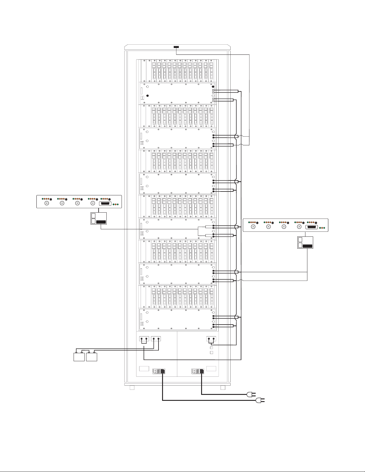
Figure 4, 72 Line Cards Configuration (Expansion Cabinet)
Ethernet Repeater B
Ethernet Repeater A
Ethernet Repeater A
MAN
MAN
MAN
MAN
PORT 4
REC COL PAR PAR
PORT A
MAN
PWR JAM ACT
REC COL PAR PAR
PORT 1
REC COL PAR PAR
PORT 2
REC COL PAR PAR
PORT 3
REC COL PAR PAR
Fan Tray
Ethernet Repeater B
MAN
REC COL PAR PAR
PORT 2
MAN
REC COL PAR PAR
PORT 1
REC COL PAR PAR
PORT 3
MAN
MAN
PORT 4
REC COL PAR PAR
PORT A
MAN
PWR JAM AC T
REC COL PAR PAR
NOTE: Battery wiring
should be run in conduit
and batteries should be
housed in a separate UL
Listed enclosure.
Recommended batteries:
2x12V / 140-190Ah
4 hours backup batteries
used in conjunction with
power generator.
Model:INTERSTATE SG8D.
Non Power
Limited Circuit
+-+
-
WARNING: To reduce the
risk of electric shock, this
product is provided with a
grounding type power
supply cord. Connect
product to a grounded
receptacle.
POWER A
BATTERY
--
++
POWER B
120V/60Hz/10A
NOTE: AC supply
cords shall be run in
conduit or be
provided with
equivalent
mechanical
protection.
6
2.1.4 Signaling/Supervisory Connections
Figure 5, 60 Line Cards Configuration
7
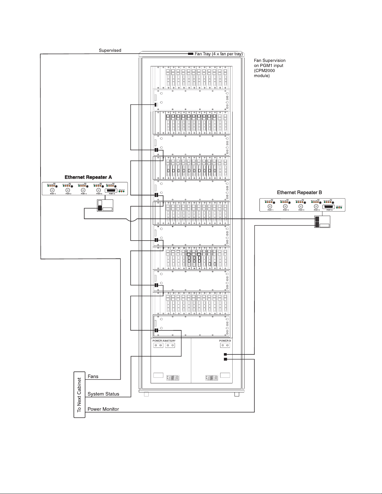
Figure 6, 72 Line Cards Configuration (Expansion Cabinet)
8

2.2 Bench Testing
It is suggested that the receiver be tested before actual
installation; becoming familiar with the connections and
setup of the unit on the work bench will make final installation more straightforward.
The following items are required:
• 28 VDC Power supply
• One telephone line
• One or more dialer or digital dialer control panels
2.2.1 Power Up
When the 28 V
will beep for approximately 1-2 minutes during system initialization. The buzzer will deactivate as soon as the
CPM2000 software initializes and is running. The LCD display on the CPM2000 should display 'Primary'. If the Line
Cards do not have telephone lines connected, the
DRL2000 modules will activate 'Line Fault' lights. The telephone line should be connected to the POTS jack at the
back of the DRL SUBRACK. As soon as the line card
detects a phone line, a line restore message will be sent to
the printer and computer output. If the phone line is
removed, a line fault message will be sent to the printer
and computer output.
If there is no computer or printer connected, a trouble
message will be displayed on the CPM2000 LCD and the
'ACK' light will flash. Press the [ACK] button to silence the
CPM2000 buzzer.
The watchdog LED on the line card should flicker as soon
as it is initialized. The Trouble LED will activate if the line
card is not receiving a poll from the CPM2000. As soon as
the line card responds to the polling, the Trouble LED
should deactivate.
2.2.2 Operation with Default Programming
Without any changes to the factory default programming,
the receiver operates as follows:
• Answers incoming calls on the first ring
• Sends 2300 Hz as the first handshake
• Sends 1400 Hz as the second handshake
• Sends dual tone as the third handshake
• Sends SIA FSK tone as the fourth handshake
• Sends ITI , Modem IIE/ IIIa
• Sends Modem II tone as sixth handshake
• Receives all communication formats, except for: 3/2, 4/1
express, 4/2 extended and 4/2 checksum.
• The above formats can be manually selected.
• Signals can be displayed on the debug output computer
as they are received. The signals are then sent to the
parallel printer and computer connected to serial port
COM1 or to the 10BT connector. The default event
codes described in the 'DRL2000 Library Decoding and
Event Codes Table' will be used with the Sur-Gard automation communication protocol to send signals to the
computer, if connected.
• If a computer is not connected, press the [ACK] button
on the CPM2000 module to silence the buzzer.
DC power is applied, the CPM2000 unit
2
tone as fifth handshake
2.2.3 Debug Output
The debug output is another means of accessing the linecard's programmed options and diagnostics features. A
debug cable is required to connect by serial communication from the line card to a standard PC running Windows
9x/2000/XP.
2.2.4 Debug Cable Connectivity
• Connect the RJ45 end of the debug cable to the debug
jack on the front of the line card or to the debug jack of
the paddle board on the back of the sub-rack.
• Connect the female DB-9 connector to the serial port of
a computer (COM1 port - usually DB-9 male, COM2
port - DB-25 female).
2.2.5 Debug Software Setup
• Using WIN95, point and click on the 'START' button.
Access 'Programs' -> 'Accessories' -> 'HyperTerminal'.
Once in the HyperTerminal window, point and click on
'Hypertrm.exe' icon.
• A connection description window should appear. A
prompt should appear on the 'Name' category. Type a
name. Point and click on the 'OK' button.
• A phone number window should appear. Choose the
direct to COM port required for connection and point
and click on 'OK'.
• COMX properties windows should appear. The configuration should be:
• Bits per second: 19200
•Data bits: 8
• Parity: None
• Stop bits: 1
• Flow control: None
• Point and click on the 'OK' button after setting the configuration.
• The HyperTerminal window should appear. Press any
button. The debug menu will be displayed.
2.2.6 Button Commands
A:This button will display the address of the line card. The
address includes the shelf and slot number of the line
card making each line card unique.
D:This button will initiate the download of a file to the
line card.
O:This button will enable the user to dump the current
programmed options of the line card or set an option
to a particular value.
P:Sets the message priority to be displayed. This is useful
for debugging purposes only.
2.2.7 Downloading steps
1. Press the 'D' button to initiate downloading of the
binary file. The Hyper Terminal will display:
Ready to download.
CCCC
2. Point and click at 'Transfer' on the Hyper Terminal
menu and access the 'Send File' category. The 'Send
File' window should appear.
3. Change the protocol to 'X-modem' and place the correct path and file name of the binary file to be downloaded.
4. Point and click on the [Send] button and the downloading status window should appear.
The line card will restart automatically after a successful
download.
2.2.8 Printer output
Printer Examples:
Date Time SS/00 Receiver Type Receiver # Line # Account # Alarm Code Message
Ex. JUN 01 2000 - 08:00:22 - 01/02 -SG - 01 - 061 - 965 - E9 RESTORE
Ex. JUN 01 2000 - 08:00:22 - 01/02 -SG - 01 - 061 - 965 - F9 TROUBLE
Ex. JUN 01 2000 - 08:00:22 - 01/02 -SG - 01 - 061 - 965 - 2 PANIC ALARM
9
Section 3 - Installation
3.1 Dimensions
The MLR2000 is implemented into a 42U * 600 mm *
800 mm cabinet. The cabinet has 7 subracks, each on is
19 inches * 6U high. Housed in the top subrack, the
CPM2000 comes complete with its own 19 inch * 6U
tray. Bellow the CPM2000 tray, the MLRX-2000 expansion
cage provides for up to 12 DRL2000 line cards. Each
DRL2000 line card is 6U * 6HP * 220 mm. Each paddle
board is 3U * 6 HP * 220 mm. The PSU-2000 comes complete in its own 19 inch * 6U high cage.
The main MLR2000 cabinet will hold 2×CPM2000,
5×MRLX-2000, 60×DRL2000, 2×PSU-2000.
The expansion MLR2000 cabinet will hold 6×MRLX-2000,
72×DRL2000, 2×PSU-2000.
3.1.1 Spacing
All units of a receiver must be within 50 ft. (cable length)
of the CPM to provide system timing integrity.
3.2 Definity DNIS
The AT&T Definity G3 DTMF vdn codes have been tested
and are supported by the MLR2000.
3.3 Mounting the Receiver
Install the MLR2000 in a closed 19" rack or cabinet with a
locking rear access door. Cover all unused spaces with
blank metal plates. The LCD screen on the receiver is
designed to be viewed below eye level. A Stand-up Unit
(61.25" tall up to 60 telephone lines, part #90000016)
can be supplied for a complete installation.
NOTE: If 60 telephone lines are not used, cover each
unused location with a blank plate.
3.4 Printer Connections
The following UL Listed printers can be used with the
MLR2000: Sur-Gard CPU-1150 (Panasonic KX-P1150)
DMP SCS-PTR (Okidata Microline 182/184)
Connect the parallel printers to the MLR2000 printer output ports using parallel printer cables.
NOTE: A minimum of two printers are required for
UL Listed applications.
Do not use a printer cable which has only 1 common
ground wire.
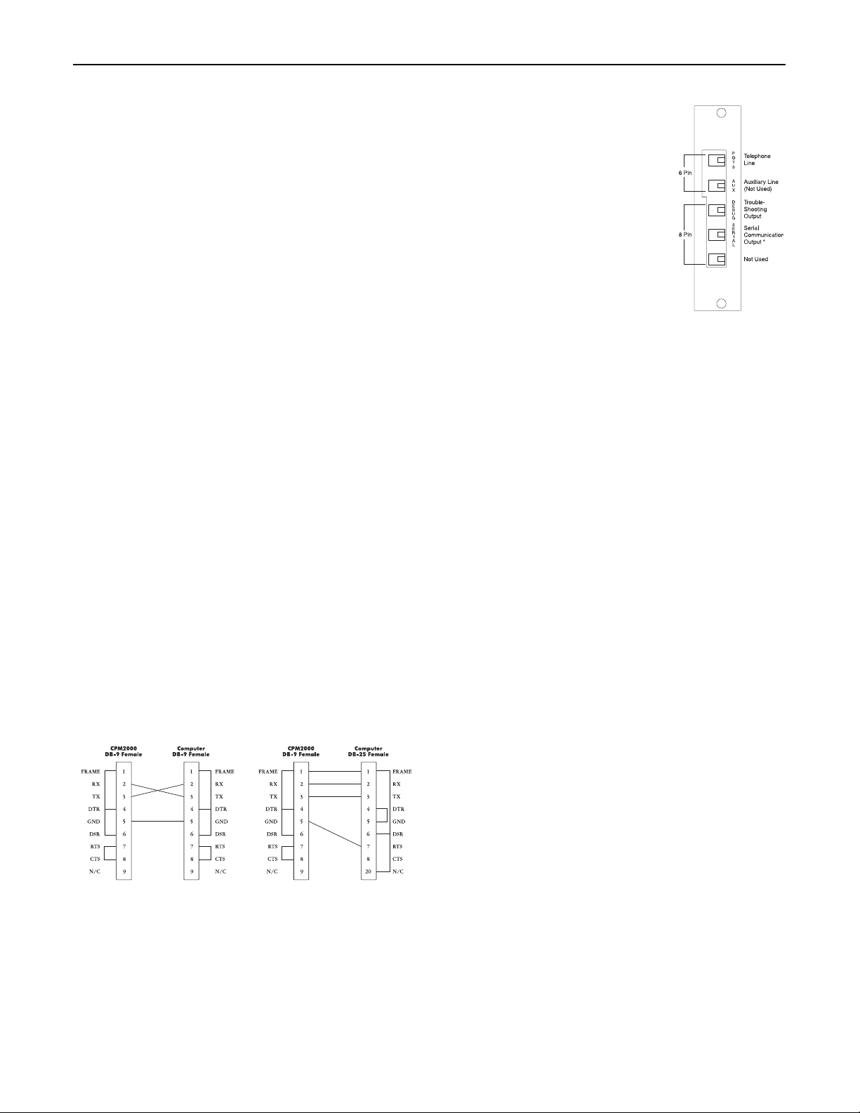
3.5 Computer Connections
Connect the computer to the MLR2000 RS232 port using
a serial cable to COM1.
NOTE: Pins 1, 4 and 6 on the receiver side are connected together. Pin 7 and 8 are also shorted
together. Pin 9 is not connected.
3.6 Telephone Line
Connections
Each paddle module has the connections shown here. Connect each
line module output (POTS) to the
telephone line (analog) with 6-pin
modular cables.
NOTE: Use minimum AWG 26
wires for telephone cables.
*NOTE: Connection of an Ademco radio
receiver model 7810RT or 7830R can be
done on the serial port of the paddle
module. The device should be mounted
in the same room as the MLR2000
receiver (within 20 ft.). The connection
shall be run in conduit or equivalent i.e.
providing mechanical protection.
3.7 Grounding
For maximum resistance to static and electrical noise, the
19" rack frame must be connected to earth ground
through the AC utility box.
3.8 Power Supply
Ensure that all electrical connections are made correctly.
After verifying all connections, connect the RED and
BLACK leads to a 24 (2 × 12V batteries in series) VDC
sealed rechargeable battery. Be sure to observe polarity
when connecting the battery. When the battery is connected, test the system under battery power only.
CAUTION: Connecting a positive (+) terminal
to a negative (-) terminal may cause a fire and
possibly serious personal harm.
3.9 Battery Charging Current
The maximum battery charging current is factory set at 5A.
3.10 Removing and Installing System
Components
To remove the Power Supply Modules
The Power Supply charges the battery and provides low
battery voltage disconnect; removing the power supply
module will disconnect the battery and shut down the
entire system. Please make sure there is a second power
supply module installed.
To Remove the CPM2000 Module
Slowly pull the module out of the metal cabinet.
To Remove a Line Card Module
Slowly pull the module out of the sub rack.
3.11 To Install a Line Card Module
Slowly insert the module in the sub rack.
Installation Checklist (Complete Operation)
❑ 19" Rack Mount Cabinet connected to earth ground
❑ SG-PSU2000 Power Supply installed
❑ 6-pin modular cable(s) connected to DRL2000 and tele-
phone line
❑ Parallel Printer Cable connected to MLR2000 Parallel
Printer Port
❑ Parallel Printer power connected
❑ Computer connected to MLR2000 COM1 port using
serial cable
❑ Computer connected to MLR2000 10BT port using
10BT cable
10
Section 4 - DRL2000 Digital Receiver Line Card
The DRL2000 acts as an interface between the digital
alarm transmitter and the CPM2000. Different communication formats can be used to transmit the information.
The main functions of the line-cards are to continuously
monitor the telephone line, receive calls from digital dialers or control panels, and to report alarms to the
CPM2000. In addition, if a Line Card is unable to communicate with the CPM2000, then each Line Card is capable
of functioning independently. Each Line Card can record
256 different alarm messages and 256 Caller-ID telephone
numbers.
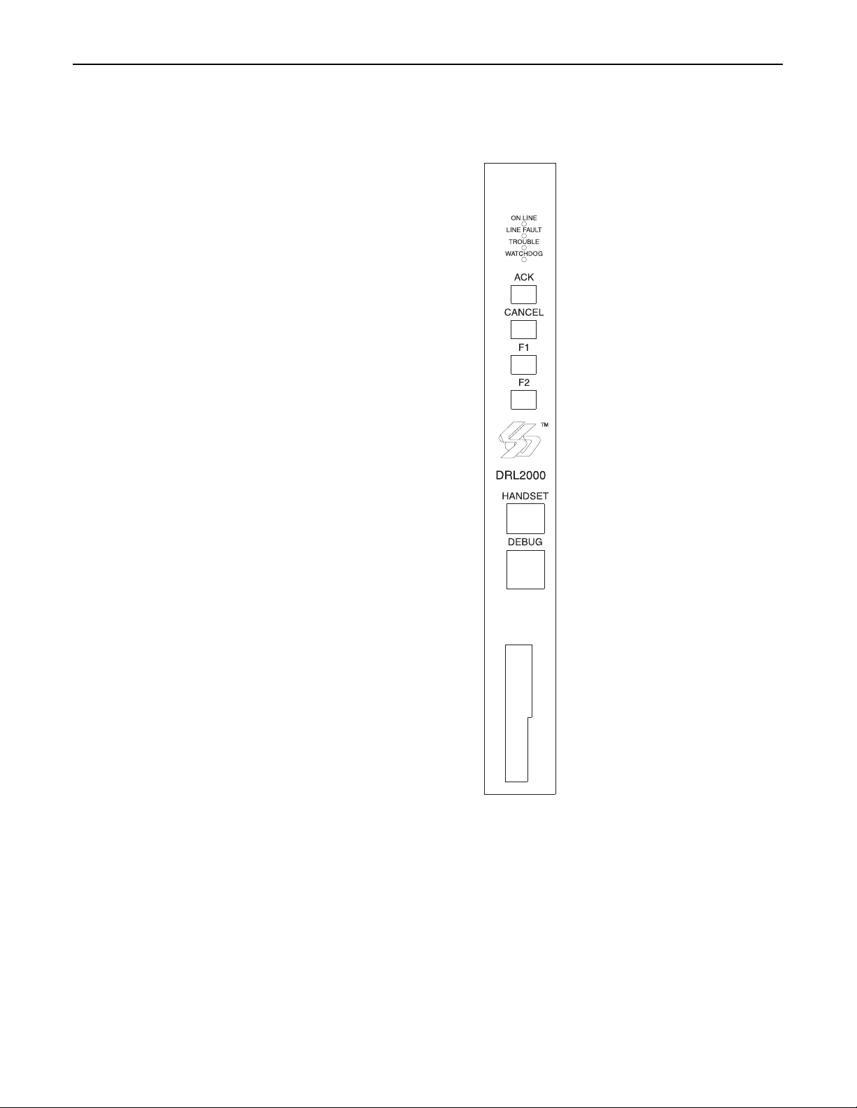
4.4 DRL2000 Controls
4.1 General Information
The receiver is capable of processing signals from digital
communicators in variety of formats. The type of signal
(alarm, trouble, restore, cancel and so on) can be printed.
4.2 DRL2000 Features
• Operator selection of communication formats and
handshake priority
• 64 profiles per line card, up to 255 line pools.
• On-Board Ethernet interface.
• Flash Download for software upgrades.
• Records up to 256 messages.
• Records up to 256 Caller-ID phone numbers. This feature helps locate and identify the source of the device in
communication and assists in troubleshooting
• Multiple alarms are forwarded to the computer and
printer through the CPM2000 with minimum delay
• The DRL2000 monitors the telephone line connection,
and line faults will result in reports to the computer and
the printer
• DRL2000 automatically goes into stand-alone mode in
case of CPM2000 failure
• 'Watchdog' timer continually monitors receiver operation
• 'Cold boot' option allows receiver's configuration to be
reset to factory default programming
• DSP processing to reduce data receiving errors, and to
help for weak and noisy signals
• Gain boost available to amplify weak signals
• Serial link for troubleshooting
4.3 Installation
It is recommended that a DRL2000 Cold Start-up be performed when the unit is updated with a new program
version. Refer to Operating Mode Section (DRL2000 Cold
Start-up for information.
After the cold start-up, check the configuration information listed in the Quick Reference Guide to make any
required changes for your particular application.
Each DRL2000 Module has one telephone line.
Momentarily depressing and releasing a button will regis-
ter as a single input or keystroke.
ON LINE: The 'on-line' light will be
ON when the Line Card is on-line in
communication. The 'on-line' light will
be OFF when the Line Card is in Standby Mode. When the line card is on-line
but not in communication, the on-line
LED will FLASH to indicate that the
buffer is full, or that there is a checksum error after download.
LINE FAULT: The 'Line Fault' light will
come ON if the telephone line is disconnected. The 'Line Fault' light will
turn OFF automatically when the telephone line is restored.
TROUBLE: The 'Trouble' light will
come ON when the Line Card is shut
down by an operator's command or
when communication with the
CPM2000 is interrupted. The 'Trouble'
light will be shut OFF when the trouble
condition is corrected.
WATCHDOG: The 'Watchdog' light
will FLASH to indicate that Line Card
operation is being monitored
[ACK] Button: Not used.
[CANCEL] Button: Not used.
HANDSET: Not used.
DEBUG: Connection to a PC for trou-
bleshooting.
[F1] + [F2] Buttons: Press and hold
both buttons simultaneously on power
up for 10 seconds will reset the line
card to factory default.
11

Section 5 - DRL2000 Operating Mode
5.1 DRL2000 Standby Mode
After start-up the Line Card enters the Stand-by Mode
and monitors the telephone line and the CPM2000.
Depending on the system's status, the following conditions will be indicated:
• Line Fault light
• Trouble light: of Line Card communication problem with
CPM2000
5.1.1 Line Fault
The DRL2000 verifies the telephone line voltage. The 'Line
Fault' light will come ON when the voltage drops below
12V.
If the Line Check option is enabled, the following information will be transmitted to the printer and computer:
•Printer:
Jul 17 1998-08: 08: 28-SS/OO-SG-RR-LLL-0000PHONE LINE TROUBLE
• Computer:0RRLLL[#0000¦NLTSSOO][DC4]
A hexadecimal number from 00 to 0B representing the
slot number of the Line Card will be sent for each 'O'
shown above.
A hexadecimal number from 01 to FE representing the
shelf number of the Line Card will be sent for each 'S'
shown above.
If the Line Check option is disabled, the DRL2000 will not
send the report to the printer or computer. Refer to
'DRL2000 Programmable Features' for information on
enabling the Line Check option.
When the line condition returns to normal, the 'Line Fault'
light will be shut OFF.
If the Line Check option is enabled and the telephone line
returns to normal, the following information will be transmitted to the printer and computer:
•Printer:
Jul 17 1998 - 08: 08: 35-SS/OO-SG-RR-LLL-0000PHONE LINE RESTORE
• Computer:0RRLLL[#0000¦NLRSSOO][DC4]
5.1.2 CPM2000 Error
If the DRL2000 cannot detect CPM2000 polling, the trouble light will come on.
If alarm messages cannot be sent to the CPM2000
because of the error, the DRL2000 will start buffering
incoming calls.
Up to 256 alarm messages for the printer and computer
will be retained in the DRL2000 event buffer. When the
event buffer is full, the line card will stop answering the
calls.
When the CPM2000 Error condition is corrected, the
alarm messages in the event buffer will be transmitted to
the CPM2000 with the corresponding time/ date the
alarm have been received.
5.2 DRL2000 Cold Start-up
To perform a Cold Start-up, press the [F1] and [F2] buttons
simultaneously for 10 seconds after a power up.
5.3 Communications in Progress
5.3.1 Data Reception
During data reception, the on-line LED will turn on. The
DRL2000 decodes all information received and stores the
information in its Event Buffer. When a valid signal is
received, the DRL2000 sends a kiss-off signal and transmits the decoded alarm signal to the computer and then
to the printer through the CPM2000.
The DRL2000 will send each message it receives to the
printer for review by the system operator. Two messages
may be sent to the printer to indicate reception problems:
the 'Fault Data' and 'Fault Call'.
5.3.2 Fault Data Message
When this problem is encountered, the following information is transmitted to the printer and the computer:
•Printer:
Jun 25 1998-11:18:07-SS/OO-SG-12-234-0000INVALID REPORT
• Computer: 012234[#0000¦NYNSSOO][DC4]
This output for account code '0000' indicates that data
has been received, but is not valid (for example, there are
unmatched rounds or wrong parity).
5.3.3 Fault Call
When this problem is encountered, the following information is transmitted to the printer and the computer:
•Printer:
Jun 25 1998-11:18:07-SS/OO-SG-12-234-0000COMMUNICATION FAIL
• Computer: 0RRLLL[#0000¦NYCSSOO] [DC4]
This output indicates that a call was received, but no data
was detected. The call may have been a wrong number,
or the calling control panel was unable to connect with
the receiver's handshakes.
5.3.4 Caller ID
When Caller-ID is enabled:
•Printer:
19-Nov-1998 10:40:54 - Nov 19 1998-11:32:25- F3/
00-SG -19-069-123F—
• Computer: 419069 123F0000000000
5.3.5 Calling Name
When Calling name is enabled:
• Computer: u19069 123FSUR-GARD SECURT
•Printer:
19-Nov-1998 10:40:56 - Nov 19 1998-11:32:25-F3/00SG -19-069-123F—SUR-GARD SECURT
12
 Loading...