

Page 1
DOC 0004-SP
1
Revision 06/18/14
OPERATOR’S MANUAL
FOR LOW PROFILE
12,000 RPM 5 in. (127 mm) and 6 in. (150 mm)
RANDOM ORBITAL SANDERS
Manufacturer/Supplier
DIXON ENTERPRISES, INC.
571 BIRCH STREET LAKE ELSINORE,
CA 92530
Tel: 951-245-4200
Fax: 951-245-4299
All SurfPrepTM Random Orbital Sanders are warranted for defects in materials or workmanship for one year from the
date of delivery to the user. Combined with the SurfPrep
TM
superior quality, durability, and performance of the SurfPrepTM LP. To receive any expressed or implied warranty, tool
must be repaired by an authorized SurfPrep
TM
Service Center. The “Service Instructions” section in this document
is provided for use after completion of the warranty period. To receive warranty, tools must be operated under the
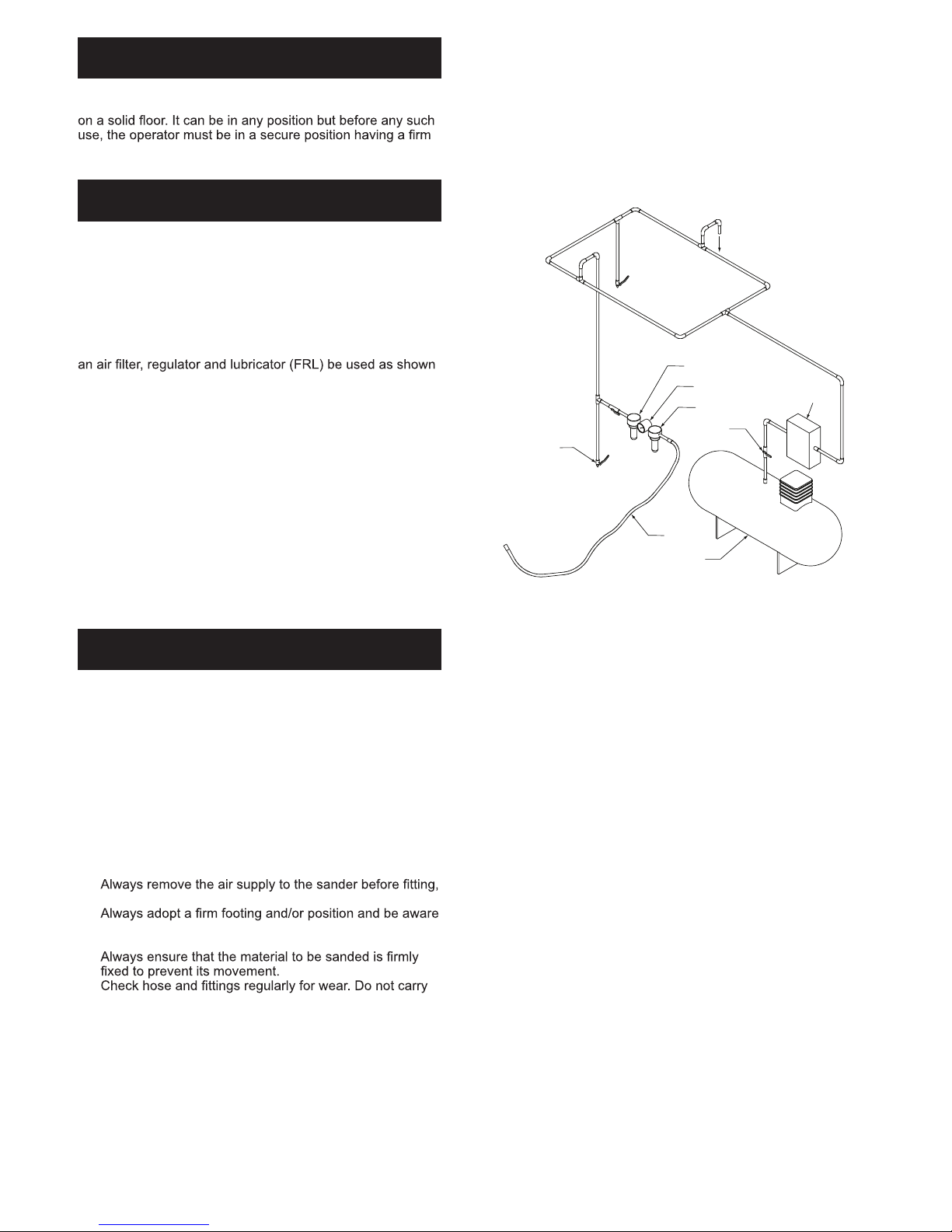
conditions as described in the “Putting the Tools into Service” section of this document and be connected to an air
supply system as shown in Figure 1. Tools that have been exposed to extreme conditions will be covered under warranty at the sole discretion of SurfPrep
TM
Warranty
Please Read and Comply with:
Proper Use of Tool
1) General Industry Safety & Health Regulations, Part 1910, OSHA 2206, available from: Superintendent of Docu-
2) Safety Code for Portable Air Tools, ANSI B186.1 available from: American National Standards Institute, Inc.; 1430
Broadway; New York, New York 10018
3) State and Local Regulations.
This sander is designed for sanding all types of materials i.e. metals, wood, stone, plastics, etc. using abrasive
manufacturer or the manufacturer’s authorized supplier.
Do not use back-up pads that have a working speed less than 12,000 RPM free speed. Never use back-up pads
Required Personal Safety Equipment
Safety Glasses Breathing Masks
Safety Gloves Ear Protection
Recommended Airline
Size - Minimum
10 mm 3/8 in
Recommended Maximum
Hose Length
8 meters 25 feet
Air Pressure
Maximum Working Pressure 6.2 bar 90 psig
Recommended Minimum NA NA
Declaration of conformity
DIXON ENTERPRISES, INC.
571 BIRCH STREET LAKE ELSINORE, CA 92530
declare on our sole responsibility that the products
Table for particular Model) to which this declaration
relates is in conformity with the following standard(s) or other normative document(s) EN ISO 15744:2008. Following the provisions of
89/392/EEC as amended by 91/368/EEC & 93/44/EEC 93/68/EEC Directives and consolidating Directive 2006/42/EC
Place and date of issue Name Signature or equivalent marking of authorized person
Important
Read these instructions carefully before installing, operating,
servicing or repairing this tool.
Keep these instructions in a safe
accessible location.
03.20.2013
Meri Faria
Operator Instructions
Includes – Please Read and Comply, Proper Use of Tool,
Parts Page, Parts List, Work Stations, Putting the Tool Into
Service, Operating Instructions and Compressor Layout,
Back-Up Pads, Service Tools and Accessories, Overhaul
Service Kit, Spare Part Kits, Service Instructions.
Original Instructions
Page 2
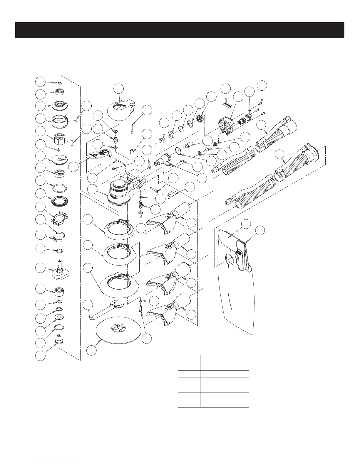
Parts Page
ITEM
TORQUE SETTING
in.-lbs. (Nm)
12
55 - 65 (6.2 - 7.3)
57
16 - 20 (1.8 - 2.3)
51
8.7 (1.0)
42
26.0 (2.9)
16
30 - 35 (3.4 - 3.9)
DOC 0004-SP
2
Revision 06/18/14
66
5
1
2
3
4
61
6
7
8
9
10
11
12
13
15
17
18
19
20
21
22
23
24
25
26
27
28
29
30
31
34
35
36
37
38
39
27
40
25
41
42
43
44
45
46
47
27
52
54
55
56
57
58
49
50
51
59
14
53
48
32
33
65
64
16
60
62
TO VACUUM
SYSTEM FOR
CENTRAL VAC
67
63
Page 3

Parts List
Item No. Part No. Description Qty.
1 SPA0040 EXTERNAL RETAINING RING 1
2 SPA0021 10X26X8 BEARING -2 SHIELDS 1
3 SPB0017 REAR ENDPLATE 1
4 SPA0005 20 mm CYLINDER ASSEMBLY 1
5 SPA0042 5 mm X 2.0mm O-RING 1
6 SPB0005 MACHINED ROTOR 1
7 SPA0010 VANE 5
8 SPA0041 3mm X 13mm WOODRUFF KEY 1
9 SPG0001 FRONT ENDPLATE 1
10 SP50059 15 X 32 X 9 BEARING - 2 SHIELDS 1
11 SPA0045 39.4 mm X 3.1 mm O-RING 1
12 SPF0002 LOCK RING 1
13 SPG0002 COOLING FAN 1
14 SP50012 SMALL SPACER-COOLING FAN 1
15 SP50013 LARGE SPACER-COOLING FAN 1
16 SPF0020 FRONT BEARING DUST SHIELD 1
17 SPG0004 5 X 3/32 in. ORBIT NON-AirSHIELD Plus TM SHAFT BALANCER 1
17 SPG0003 5 X 3/16 in. ORBIT NON-AirSHIELD Plus TM SHAFT BALANCER 1
17 SPG0006 6 X 3/32 in. ORBIT NON-AirSHIELD Plus TM SHAFT BALANCER 1
17 SPG0005 6 X 3/16 in. ORBIT NON-AirSHIELD Plus TM SHAFT BALANCER 1
18 SPA0938 12 X 28 16 DOUBLE ROW ANGULAR CONTACT BEARING - 1 SEAL 1
19 SPA0016 SPACER 12.1 ID X 18.0 OD X0.2 THK 1
20 SPA2542 SPINDLE BEARING DUST SHIELD 1
21 SPA0017 BELLEVILLE W ASFER 1
22 SPA0018 RETAINING RING 1
23 SPB0018 SPINDLE 1
24 SPG0024 GRIP (3in. 75mm) 1
25 SPA0039 INTERNAL RETAINING RING 2
26 SPF0001 SPEED CONTROL (PRESET) 1
27 SPA0043 9 mm X 1.5 mm O-RING 3
28 SPF0024 THROTTLE LEVER FOR AIRVANTAGE 12,000 RPM 2.5 mm (3/32 in.) ORBIT SANDER 1
SPF0022 THROTTLE LEVER FOR AIRVANTAGE 12,000 RPM 5.0 mm (3/16 in.) ORBIT SANDER 1
29 SPA0031 LEVER SPRING PIN 1
30 SPG0031 MACHINED HOUSING 1
31 SPH0004 5in. / 6in. NON-VACUUM SHROUD 1
32 SPH0005 5 in. CV.SGV SHROUD 1
33 SPH0006 6 in. CV.SGV SHROUD 1
34 SPA0022 24 mm PAD W RENCH 1
35 NA 1 PAD SUPPLIED WITH EACH TOOL 1
36 SPA0008 VALVE STEM ASSEMBLY 1
37 SPA0015 VALVE SLEEVE 1
38 HN2-04CA M4 NUT 1
39 S6-0430A HEX.SOCKET BUTTON HEAD SCREW (M4x30L) 1
40 SPF0003 SPEED CONTROL 1
41 PW1-050D PLAIN WASHER (M5 X10) 1
42 S6-0520A HEX. SOCKET BUTTON HEAD SCREW (M5X20L) 1
43 SPF0008 MUFFLER CAP 1
44 SPF0011 MUFFLER INSERT 1
DOC 0004-SP
3
Revision 06/18/14
Page 4

Parts List
Item No. Part No. Description Qty.
45 SPF0012 O-RING (20 mm X 1 mm NBR70) 1
46 SPF0009 SGV EXHAUST CAP 1
47 SPF0010 VARIABLE EXHAUST 1
48 SPF0021 LOGO INSERT - END CAP 1
49 SPG0023 END CAP 1
50 SPA2474 INLET BUSHING ASSEMBLY 1
51 S6-0410 HEX.SOCKET BUTTON HEAD SCREW (M4X10L) 3
52 SPG0030 EXHSUST CHAMBER 1
53 SPA2204 9.5 mm X 1.0 mm O-RING 1
54 SPA2484 24 mm X 1.0 mm O-RING 1
55 SPF0013 INTERNAL MUFFLER 1
56 SPA0009 VALVE SEAT 1
57 SPA0007 VALVE 1
58 SPA0014 VALVE SPRING 1
59 SPF0015 NON-VACUUM COVER 1
60 SPG0021 5 in. SGV SWIVEL EXHAUST FITTING - 3/4 in./19mm HOST OPT
SPG0023 6 in. SGV SWIVEL EXHAUST FITTING - 3/4 in./19mm HOST OPT
61 SPG0022 5 in. CV SWIVEL EXHAUST FITTING - 3/4 in./19mm HOST OPT
SPG0024 6 in. CV SWIVEL EXHAUST FITTING - 3/4 in./19mm HOST OPT
62 SPG0013 5 in. SGV SWIVEL EXHAUST FITTING - 1 in./28mm HOST 1
SPG0015 6 in. SGV SWIVEL EXHAUST FITTING - 1 in./28mm HOST 1
63 SPG0014 5 in. CV SWIVEL EXHAUST FITTING - 1 in./28mm HOST 1
SPG0016 6 in. CV SWIVEL EXHAUST FITTING - 1 in./28mm HOST 1
64 SPA0300
Ø 3/4 in. VAC HOSE TO Ø 3/4 in. x 1 in./28 mm ADAPTER COUPLING AND AIRLINE ASSEMBLY
OPT
SPA0392
Ø 1 in. VAC HOSE TO Ø 1 in./28 mm x 1 1/2 in. ADAPTER COUPLING AND AIRLINE ASSEMBLY
OPT
65 SPA0412 Ø 1 in. VAC HOSE TO DOUBLE BAG FITTING AND AIRLINE ASSEMBLY 1
66 SPA0468 VACUUM BAG 1
67 SPA0470 VACUUM BAG INSERT 1
DOC 0004-SP
4
Revision 06/18/14
Page 5
and the physical condition of the user. SurfPrep
Orbit
Pad
Face
Vacuum
Type
Pad Type
Pad Size
in. (mm)
Model
Number.
Product
Net Weight
Pound (kg)
Height in.
(mm)
Length in.
(mm)
Power HP
(watts)
Air
Consump-
tion scfm
(LPM)
*Noise
Level
dBA
*Vibration
Level
m/s
2
*Uncer-
tainty
K
m/s
2
3/32 in.
(2.5 mm)
Vinyl
Non-
Vacuum
5 in. (127) SP051200 1.84 (0.83)
3.9 (100.6)
3.9 (100.6)
3.9 (100.6)
3.9 (100.6)
3.9 (100.6)
3.9 (100.6)
3.9 (100.6)
3.9 (100.6)
3.9 (100.6)
3.9 (100.6)
3.9 (100.6)
3.9 (100.6)
3.9 (100.6)
3.9 (100.6)
3.9 (100.6)
3.9 (100.6)
3.9 (100.6)
3.9 (100.6)
3.9 (100.6)
3.9 (100.6)
3.9 (100.6)
3.9 (100.6)
3.9 (100.6)
3.9 (100.6)
7.0 (178) .28 (209) 17 (481)
17 (481)
17 (481)
17 (481)
17 (481)
17 (481)
17 (481)
17 (481)
17 (481)
17 (481)
17 (481)
17 (481)
17 (481)
17 (481)
17 (481)
17 (481)
17 (481)
17 (481)
17 (481)
17 (481)
17 (481)
17 (481)
17 (481)
17 (481)
77.5 1.91 0.68
6 in. (150) SP061200 1.91 (0.86) 7.4 (189) .28 (209) 77.0 2.19 0.71
Central
Vacuum
5 in. (127) SP051234 1.96 (0.89) 9.0 (231) .28 (209) 76.5 1.79 0.67
6 in. (150) SP061234 2.06 (0.93) 9.5 (242) .28 (209) 75.0 2.40 0.73
Self-Gen
Vacuum
5 in. (127) SP051267 1.98 (0.90) 9.4 (239) .28 (209) 83.5 2.15 0.71
6 in. (150) SP061267 2.08 (0.94) 9.8 (250)
7.0 (178)
7.4 (189)
9.0 (231)
9.5 (242)
9.4 (239)
9.8 (250)
7.0 (178)
7.4 (189)
9.0 (231)
9.5 (242)
9.4 (239)
9.8 (250)
7.0 (178)
7.4 (189)
9.0 (231)
9.5 (242)
9.4 (239)
9.8 (250)
.28 (209) 82.5 2.20 0.71
Hook
Non-
Vacuum
5 in. (127) SP051202 .28 (209)
6 in. (150) SP061202 .28 (209)
Central
Vacuum
5 in. (127) SP051236 .28 (209)
6 in. (150) SP061236 .28 (209)
Self-Gen
Vacuum
5 in. (127) SP051269 .28 (209)
6 in. (150) SP061269 .28 (209)
3/16 in.
(5.0 mm)
Vinyl
Non-
Vacuum
5 in. (127) SP051300 1.88 (0.85) .28 (209) 76.0 2.79 0.77
6 in. (150) SP061300 1.97 (0.89) .28 (209) 76.0 2.92 0.78
Central
Vacuum
5 in. (127) SP051334 2.00 (0.90) .28 (209) 77.0 2.64 0.76
6 in. (150) SP061334 2.12 (0.96) .28 (209) 76.0 1.99 0.69
Self-Gen
Vacuum
5 in. (127) SP051367 2.02 (0.91) .28 (209) 84.0 2.51 0.74
6 in. (150) SP061367 2.14 (0.97)
1.84 (0.83)
1.91 (0.86)
1.96 (0.89)
2.06 (0.93)
1.98 (0.90)
2.08 (0.94)
1.88 (0.85)
1.97 (0.89)
2.00 (0.90)
2.12 (0.96)
2.02 (0.91)
2.14 (0.97)
.28 (209) 82.5 2.08 0.70
77.5 1.91 0.68
77.0 2.19 0.71
76.5 1.79 0.67
75.0 2.40 0.73
83.5 2.15 0.71
82.5 2.20 0.71
76.0 2.79 0.77
76.0 2.92 0.78
77.0 2.64 0.76
76.0 1.99 0.69
84.0 2.51 0.74
82.5 2.08 0.70
Hook
Non-
Vacuum
5 in. (127) SP051302 .28 (209)
6 in. (150) SP061302 .28 (209)
Central
Vacuum
5 in. (127) SP051336 .28 (209)
6 in. (150) SP061336 .28 (209)
Self-Gen
Vacuum
5 in. (127) SP051369 .28 (209)
6 in. (150) SP061369 .28 (209)
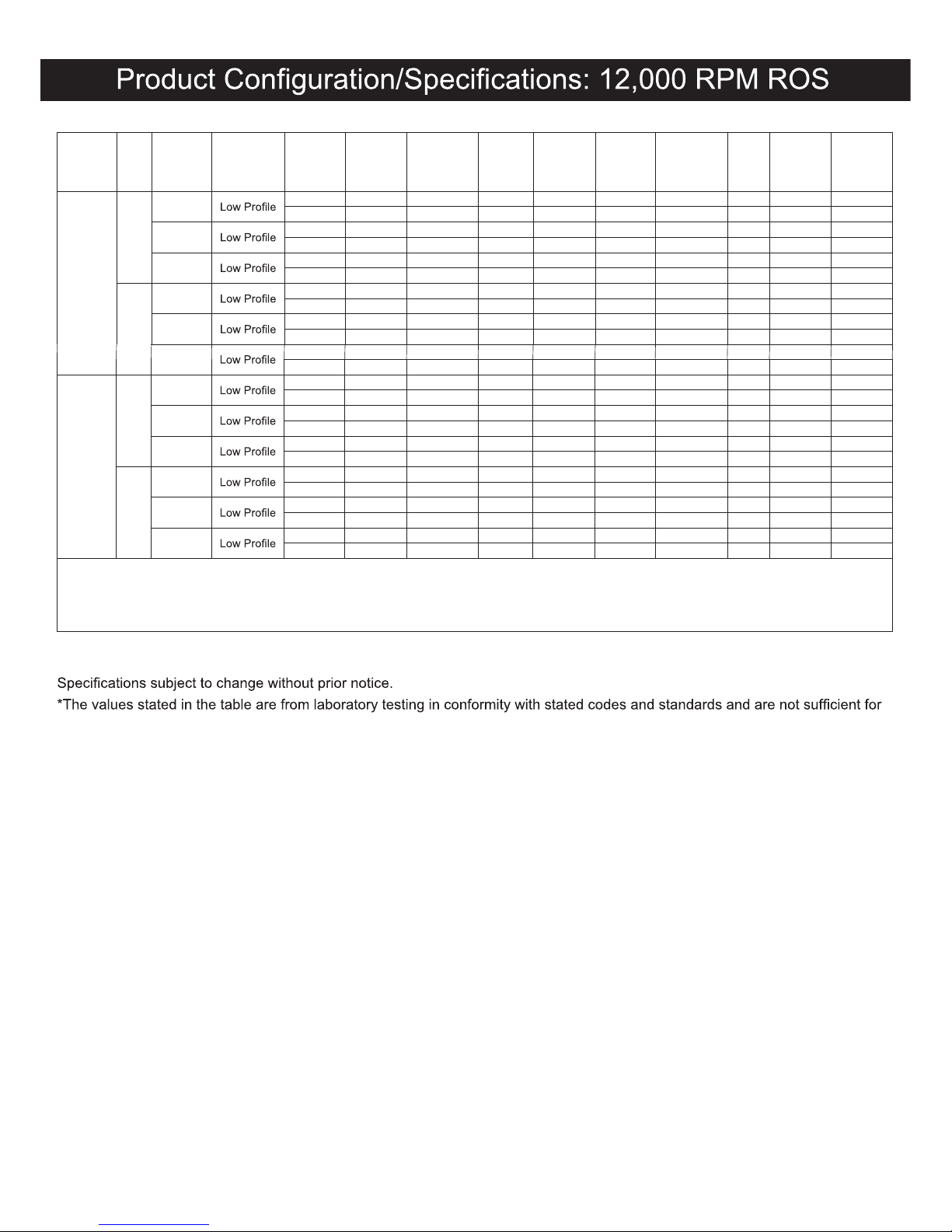
The noise test is carried out in accordance with EN ISO 15744:2008 Measurement of noise emission from hand-held non-electric power tools.
The vibration test is carried out in accordance with EN 28662-1. Hand-held portable power tools – Measurement of vibration at the handle. Part 1:
General and EN 8662-8, 1997. Hand-held portable power tools – Measurement of vibration at the handle. Part 8: Polishers and rotary
, orbital and
random orbital sanders
risk evaluation. Values measured in a particular work place may be higher than the declared values. The actual exposure values
and amount of risk or harm experienced to an individual is unique to each situation and depends upon the surrounding environment,
the way in which the individual works, the particular material being worked, work station design as well as upon the exposure time
TM
cannot be held responsible for the consequences of using declared values
instead of actual exposure values for any individual risk assessment.
Further occupational health and safety information can be obtained from the following websites:
http://europe.osha.eu.int (Europe)
http://www.osha.gov (USA)
DOC 0004-SP
5
Revision 06/18/14
Page 6
Work Stations
Putting the Tool into Service
Operating Instructions
1) Read all instructions before using this tool. All operators
must be fully trained in its use and aware of these safety
rules. All service and repair must be carried out by
trained personnel.
2) Make sure the tool is disconnected from the air supply.
Select a suitable abrasive and secure it to the back-up
pad. Be careful and center the abrasive on the back-up
pad.
3) Always wear required safety equipment when using this
tool.
4) When sanding always place the tool on the work then
start the tool. Always remove the tool from the work
before stopping. This will prevent gouging of the work
due to excess speed of the abrasive.
5)
adjusting or removing the abrasive or back-up pad.
6)
of torque reaction developed by the sander.
7) Use only correct spare parts.
8)
9)
the tool by its hose; always be careful to prevent the tool
from being started when carrying the tool with the air
supply connected.
10) Dust can be highly combustible. Vacuum dust collection
bag should be cleaned or replaced daily. Cleaning or
replacing of bag also assures optimum performance.
11) Do not exceed maximum recommended air pressure.
Use safety equipment as recommended.
12) The tool is not electrically insulated. Do not use where
there is a possibility of coming into contact with live
electricity, gas pipes, water pipes, etc. Check the area of
operation before operation.
The tool is intended to be operated as a hand held tool. It is
always recommended that the tool be used when standing
grip and footing and be aware that the sander can develop a
torque reaction. See the section “Operating Instructions”.
Use a clean lubricated air supply that will give a measured
air pressure at the tool of 90 psig (6.2 bar) when the tool is
running with the lever fully depressed. It is recommended
to use an approved 3/8 in. (10 mm) x 25 ft (8 m) maximum
length airline. It is recommended that the tool be connected
to the air supply as shown in Figure 1.
Do not connect the tool to the airline system without incorporating an easy to reach and operate air shut off valve. The air
supply should be lubricated. It is strongly recommended that
in Figure 1 as this will supply clean, lubricated air at the
correct pressure to the tool. Details of such equipment can
be obtained from your supplier. If such equipment is not used
then the tool should be manually lubricated
To manually lubricate the tool, disconnect the airline and put
2 to 3 drops of suitable pneumatic motor lubricating oil such
as Fuji Kosan FK-20, Mobil ALMO 525 or Shell TORCULA®
32 into the hose end (inlet) of the machine. Reconnect tool to
the air supply and run tool slowly for a few seconds to allow
air to circulate the oil. If the tool is used frequently, lubricate
it on a daily basis or lubricate it if the tool starts to slow or
lose power.
It is recommended that the air pressure at the tool be 90 PSI
(6.2 Bar) while the tool is running so the maximum RPM is not
exceeded. The tool can be run at lower pressures but should
never be run higher than 90 PSI (6.2 Bar). If run at lower pressure the performance of the tool is reduced.
13) Take care to avoid entanglement with the moving parts
of the tool with clothing, ties, hair, cleaning rags, etc. If
entangled, it will cause the body to be pulled towards the
work and moving parts of the machine and can be very
dangerous.
14) Keep hands clear of the spinning pad during use.
15) If the tool appears to malfunction, remove from use immediately and arrange for service and repair.
16) Do not allow the tool to free speed without taking precautions to protect any persons or objects from the loss of
the abrasive or pad.
Closed Loop Pipe System
Sloped in the direction
of air flow
Drain Leg
Ball Valve
To Tool Station
Filter
Drain Valve
Regulator
Lubricator
Ball
Valve
Ball Valve
Air Flow
Air Dryer
Air Compressor
and Tank
Air Hose
To Coupler
at or near Tool
Figure 1
DOC 0004-SP
6
Revision 06/18/14
Page 7
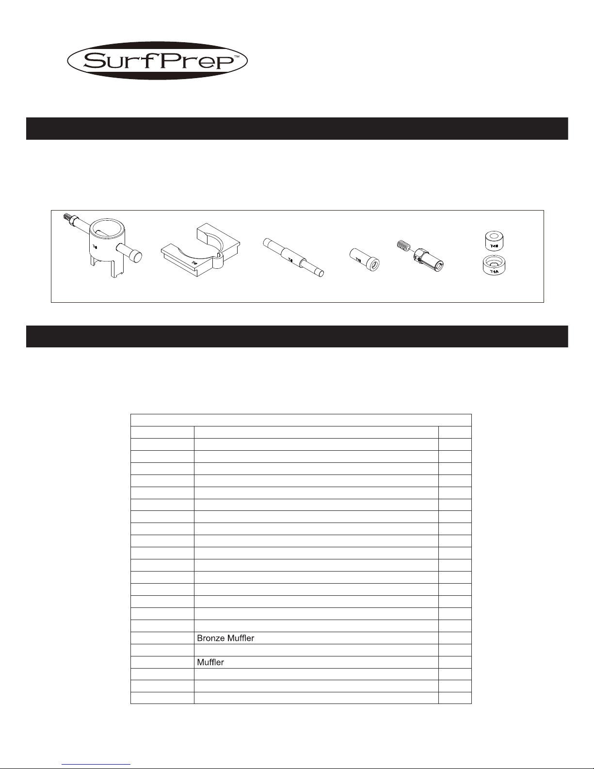
SPF0033 Overhaul Service Kit for 12,000 RPM 5 & 6 in. ROS Contents
Part No. Description Qty.
SPA0040 External Retaining Ring 1
SPA0021 Bearing 1
SPA0042 O-Ring 1
SPB0005 Rotor 1
SPA0010 Vanes 5
SPA0041 Key 1
SP50059 Bearing 1
SPA0937 Shim 1
SPA0938 Bearing 1
SPA0016 Spacer 1
SPA0008 Valve Stem Assembly 1
SPA0043 O-Ring 1
SPA0039 Internal Retaining Ring 1
SPF0013
SPG0030
SPA2204
SPA2484
SPF0008
1
SPF0011
1
1
SPA0009 Valve Seat
Muffler Cap
Exhsust Chamber
9.5 mm X 1.0 mm O-Ring
24 mm X 1.0 mm O-Ring
1
SPA0007 Valve
1
1
SPA0014 Valve Spring
1
1
1
Overhaul Service Kit
The SPF0033 Overhaul Service Kit contains all the replacement parts that naturally wear over time and a straightforward
manual to make servicing an SurfPrep
TM
sander simple. Overhauling the Random Orbital Sander can be made even easier with
the use of the above Service Tools. The Service Tools also reduce the chance of improper assembly.
Service Tools and Accessories
When an SurfPrepTM LP ROS needs to be serviced, we offer a tool kit to make the disassembly/assembly fast and easy. The
Service Tools are highly recommended for use with the Overhaul Service Kit. NOTICE: To receive any expressed or implied
warranty, the tool must be repaired by an authorized SurfPrep
TM
Service Center. The 5 in. and 6 in. Random Orbital Sanders
Service Instructions section provided are for use after completion of the warranty period.
T-6 MOTOR LOCK RING
WRENCH/SPINDLE PULLER
T-7 SOFT COLLAR
T-8 MOTOR FACE PLATE
BEARING REMOVAL TOOL
T-13 BEARING
PRESS TOOL
T-9 12 mm ID
BEARING PULLER
T-1 ROS SPINDLE
BEARING PRESS TOOLS
SERVICE INSTRUCTIONS
FOR LOW PROFILE 12,000 RPM
5 in. (127 mm) and 6 in. (150 mm)
RANDOM ORBITAL SANDERS
SPA0479 UNIVERSAL SERVICE TOOL KIT
DOC 0004-SP
7
Revision 06/18/14
Page 8
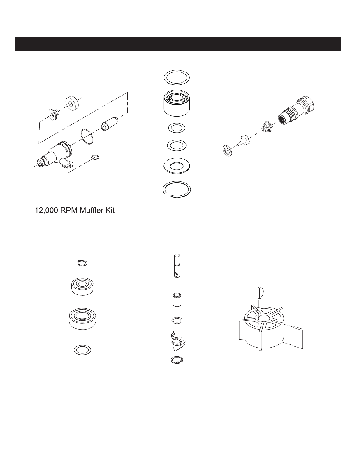
1
/4-18 NPT Air Inlet Kit
Reorder P/N SPF0029Reorder P/N SPF0028
ROS Spindle Bearing Kit
Reorder P/N SPA1164
Sander Spare Parts Kits
Endplate Bearing Kit
Reorder P/N SPF0032
Speed Valve Kit
Reorder P/N SPF0030
Rotor, Vanes and Key Kit
Reorder P/N SPA0063
DOC 0004-SP
8
Revision 06/18/14
Page 9

DISASSEMBLY INSTRUCTIONS
Changing Grips:
1. The Grip has two “tabs” that wrap around the body of
the sander under the inlet and exhaust. Use a small
screwdriver to pick out one of the “tabs” of the Grip,
and then continue to go underneath the Grip with the
screwdriver and pry the Grip off of sander. To install a
new Grip, hold the Grip by the tabs making them face
outward, align the Grip and slide it under the Throttle
Lever then press the Grip down until it seats onto the
top of the sander. Make sure the two “tabs” seat under
the inlet and exhaust.
Motor Disassembly:
1. Lightly secure the tool in a vise using the T-7 Soft Collar
or padded jaw vice and remove the pad with the 24 mm
Pad Wrench then remove the Shroud.
2. Remove the Lock Ring with the T-6 Motor Lock Ring
Wrench/Spindle Puller Tool. The motor assembly can
now be lifted out of the Housing.
3. Secure the motor assembly by clamping the 5 in. or 6
in. (125 or 150 mm) Shaft Balancer in a padded jaw vise
and remove the Retaining Ring and the O-Ring from the
Cylinder.
4. Remove the Rear Endplate. This may require supporting the Rear Endplate with a Bearing Separator and
lightly pressing the shaft through the Bearing and Rear
Endplate. Remove Cylinder and the Vanes and Rotor
Set from the shaft of the Shaft Balancer. Remove the
Key then press off the Front Endplate (with Bearing), ORing and the Lock Ring. It may be necessary to remove
the Bearing with a Bearing Separator if it came out of
the Front Endplate and stuck to the shaft of the Shaft
Balancer.
5. Remove and discard Dust Shield from the Shaft Balancer.
6. Remove the Bearing(s) from the Endplates by using the
T-8 Bearing Removal Tool to press out the Bearings.
Shaft Balancer and Spindle Disassembly:
1. Grip the shaft end of the Shaft Balancer in a padded
vise. With a thin screwdriver pick out the slotted end of
the Retaining Ring and peel out.
2. Screw the threaded end of the T-6 Motor Lock Ring
Wrench/Spindle Puller Tool into the Spindle until hand
tight. Apply a gentle heat from a propane torch or hot
air gun to the large end of the Balancer Shaft until it is
about 212° F (100° C) to soften the adhesive. Do not
over heat. Remove the Spindle assembly by using the
slider to give sharp outward blows to the Spindle. Allow
the parts to cool so they are safe to handle. Follow one
of the appropriate directions below:
• If the Bearing come out with the spindle, use a small
Bearing Separator to remove it. Move onto step 3.
• If the Bearing stays in the Shaft Balancer. Follow
steps A - D below.
Procedure for removal of the Bearings from the Shaft
Balancer:
A. Position the Set Screw in the top of the T-9 12 mm ID
Bearing Puller.
B. Make sure the Retaining Ring is removed, then press
the Bearing Puller into the I.D. of Bearing until the Bearing Puller hits the bottom of the Shaft Balancer.
C. Thread the Set Screw down until it hits the bottom of the
Shaft Balancer or becomes very tight. Grip the shaft end
of the Shaft Balancer in a padded vise.
D. Screw the threaded end of the T-6 Motor Lock Ring
Wrench/Spindle Puller Tool into the Bearing Puller until
hand tight. Apply a gentle heat from a propane torch
or hot air gun to the large end of the Shaft Balancer to
re-heat it until it is about 212° F (100° C) to soften the
adhesive. Do not over heat. Remove the Bearing by
using the slider to give sharp outward blows to the Bearing Puller. Allow the Bearing Puller, Bearing and Shaft
Balancer to cool. After cooling, unthread the T-6 Motor
Lock Ring Wrench/Spindle Puller Tool from the Bearing
Puller. Back off the set screw. Secure the Bearing Puller
and Bearings in a Bearing Separator and press out the
Bearing Puller.
3. Remove the bearing from the Spindle. Remove the
Spacer, Dust Shield and Washer from the Spindle.
Discard Dust Shield.
Housing Disassembly:
1. For Non-Vacuum (NV) and Central Vacuum (CV)
machines follow the steps outlined in Section I below.
For Self Generated Vacuum (SGV) machines follow the
steps outlined in Section III.
I. This section is for NV and CV machines.
Remove the Muffler Housing from the Housing.
Remove the Muffler insert from the cavity of the Muffler
Housing and remove the Bronze Muffler from the Muffler Housing.
A)
B)
C) For NV machines move onto D. For CV machines move
onto Section II.
D) Remove the NV Shroud. Move onto Step 2.
II. This section continued from Section I for CV Exhaust
machines:
A) Remove the Screw, and Nut.
B) Remove the Ø 1 in. (28 mm) CV Swivel Exhaust
Assembly or the Ø 3/4 in. (19 mm) CV Swivel Exhaust
Assembly from the Shroud.
C) Remove the Shroud from the Housing. Move onto step 2.
NOTICE: To receive any expressed or implied warranty, the tool must be repaired by an authorized Service Center.
The 5 in (127 mm.) and 6 in. (150 mm) Random Orbital Sander Service Instructions section provided is for use after completion of
the warranty period.
12,000 RPM – 5 in. (127 mm) and 6 in. (150 mm)
LOW PROFILE RANDOM ORBITAL SANDERS SERVICE INSTRUCTIONS
DOC 0004-SP
9
Revision 06/18/14
Page 10
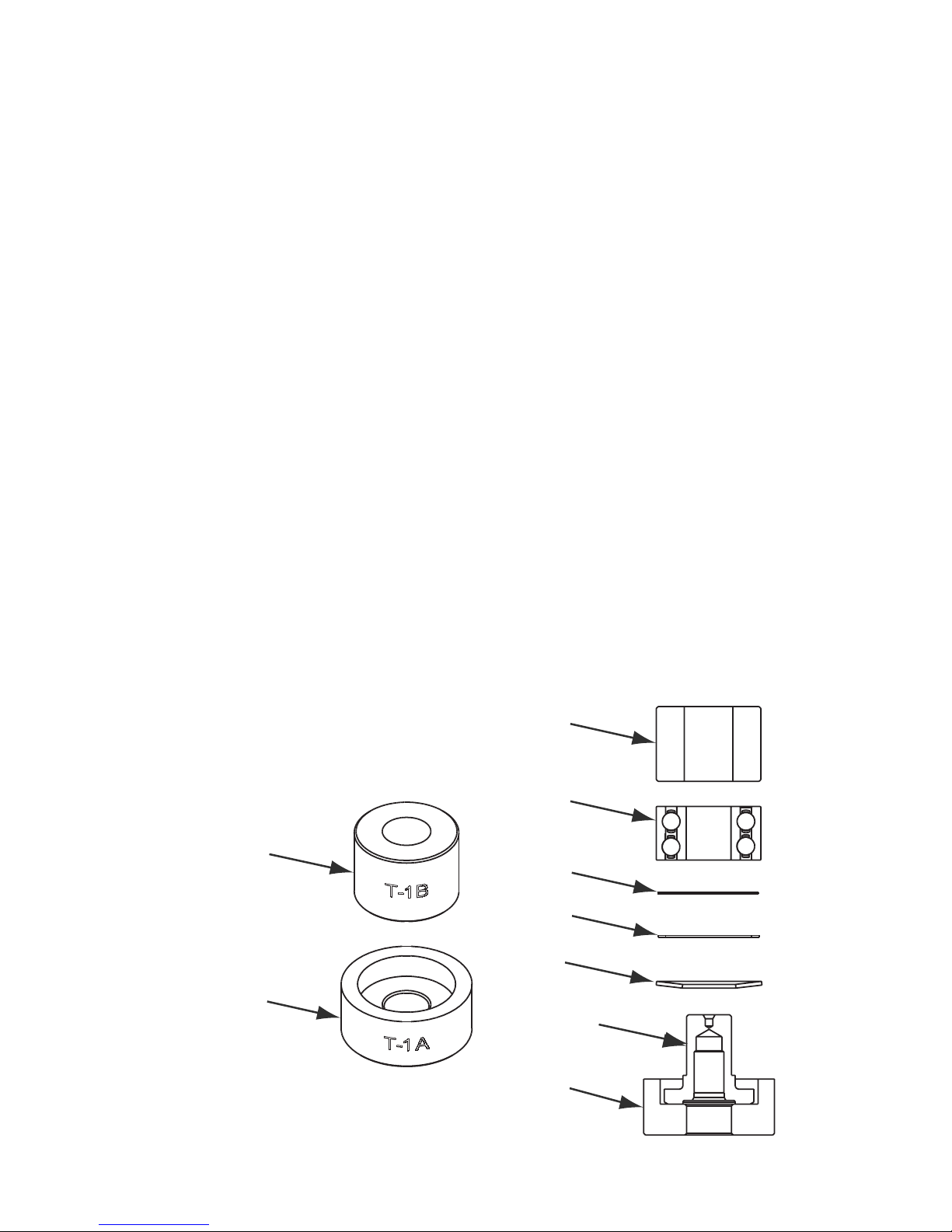
3. Install the Valve Seat, the Valve and the Valve Spring.
Coat the threads of the Bushing Assembly with 1 or 2
drops of Loctite® 222 or equivalent non-permanent pipe
thread sealant. Screw the assembly into the Housing.
Torque to 60 in/lbs (6.77 Nm.)
Press Tool Top
Press Tool Base
Dust Shield
Bearing
Washer
Spindle
T-1B
T-1A
Spacer
III. This section is for SGV Exhaust machines:
A) Remove the Screw, and Nut.
B) Remove the Ø 1 in. (28 mm) Hose SGV Swivel Exhaust
Assembly from the Housing and SGV Shroud Adapter.
C) Remove the Vacuum Shroud from the Housing. Move
onto step 2.
2. Place the Speed Control to the midway position and
remove the Retaining Ring. NOTE: If the machine is a
vacuum model, the vacuum exhaust must be removed
(see Section 1 above for removal) before the Retaining
Ring can be removed with lock ring pliers. The Speed
Control will now pull straight out. Remove the O-ring.
3. Unscrew the Inlet Bushing Assembly from the Housing.
Remove the Valve Spring, Valve, Valve Seat, Valve
Stem and O-Ring.
4. Press out the Spring Pin from the Housing and remove
the Throttle Lever.
ASSEMBLY INSTRUCTIONS
NOTE: All assembly must be done with clean dry parts and
all bearings are to be pressed in place by the correct tools
and procedures as outlined by the bearing manufacturers.
Housing Assembly:
1. Install Throttle Lever into Housing with the Spring Pin.
2. Lightly grease the O-ring and place it on the Speed
Control. Install Valve Stem, O-ring (cleaned and lightly
greased) and insert the Speed control into the Housing in the midway position. Install the Retaining Ring.
CAUTION: Make sure the Retaining Ring is completely
snapped into groove in the Housing.
DOC 0004-SP
10
Revision 06/18/14
Page 11

Spindle, and Shaft Balancer Assembly:
1. Place the Washer on the Spindle shaft with the curve of
the Washer facing up so that the outside diameter of the
Washer will contact the outer diameter of the Bearing.
Place the Dust Shield onto the Spindle shaft. Place
the Spacer onto the shoulder of the Spindle. Note: Be
sure that the Dust Shield is past the shoulder where
Spacer rests. Place the Bearing on the Spindle with the
seal side toward the Washer. Press onto Spindle using
seated at bottom.
2. When the Spindle Assembly is done correctly, the Bearing will rotate freely but not loosely.
3. Take the new Filter and center it on the small bore that
the original Filter was in before removal. With a small
Place the Valve into the bore so it is oriented correctly,
the bottom of the Bearing bore.
4. Apply a pin head size drop of #271 Loctite® or equivalent to the outside diameter of each of the bearings on
the spindle assembly. Spread the drop of bearing locker
around the bearing until distributed evenly. CAUTION:
Only a very small amount of bearing locker is needed
to prevent rotation of the bearing OD. Any excess will
sembly into the bore of the Shaft Balancer and secure
with the Retaining Ring. CAUTION: Make sure that the
Retaining Ring is completely snapped into the groove in
the Balancer Shaft. Allow the adhesive to cure.
Motor Assembly:
1. Place the Dust Shield onto the shaft of the Shaft Balancer.
2. Use the larger end of the T-13 Bearing Press Sleeve to
press the front Bearing (with 2 Shields) onto the shaft of
the Shaft Balancer.
3. Slide the Front Endplate with the bearing pocket facing
down onto the Motor Shaft. Gently press the Front Endplate onto the Bearing using the larger end of the T-13
Bearing Press Sleeve until the Front Bearing is seated
in the bearing pocket of the Endplate. CAUTION: Only
press just enough to seat the bearing into the pocket.
Over-pressing can damage the bearing.
4. Place the Key into the groove on the Shaft Balancer.
Place the Rotor on the Shaft Balancer, making sure that
5.
place them in the slots of the Rotor. Place the Cylinder
Assembly over the Rotor with the short end of the
Spring Pin engaging the blind hole in the Front Endplate. NOTE: The Spring Pin must project .060 in. (1.5
6.
Endplate with the T-1B Bearing Press Tool. Make sure
the T-1B Press Tool is centered on the O.D. of the outer
Assembly over the Shaft Balancer using the small end
of the T-13 Bearing Press Sleeve. The sleeve should
press only the inner race of the bearing. IMPORTANT:
The Rear Endplate and Bearing Assembly is pressed
correctly when the Cylinder is squeezed just enough
between the Endplates to stop it from moving freely
under its own weight when the shaft is held horizontal,
but be able to slide between the Endplates with a very
light force. If the assembly is pressed to tightly the
motor will not run freely. If the pressed assembly is to
loose, the motor will not turn freely after assembly in the
Housing. Secure the assembly by placing the Retaining
Ring in the groove of the Shaft Balancer. CAUTION: The
Retaining Ring must be placed so that the middle and
center portions must be securely “snapped” into the
groove in the Shaft Balancer by pushing on the curved
portions with a small screwdriver.
7. Lightly grease the O-Ring and place in the air inlet of the
Cylinder Assembly.
8. Lightly grease or oil the inside diameter of the Housing,
line up the Spring Pin with the marking on the Housing
and slide the Motor Assembly into the Housing. Make
sure the Spring Pin engages the pocket in Housing.
9. Carefully screw the Lock Ring into the Housing with the
T-6 Motor Lock Ring Wrench/Spindle Puller Tool. Torque
to 60 in/lbs (6.77 Nm.) NOTE: A simple technique to
counter clockwise with the T-6 Motor Lock Ring Wrench/
Spindle Puller while applying light pressure. You will
hear and feel a click when the lead thread of the lock
ring drops into the lead thread of the housing.
10. Spin on a new Pad and hand tighten it using a 24 mm
Pad Wrench.
Testing:
Place 3 drops of quality pneumatic air tool oil directly into
the motor inlet and connect it to a 90 psig (6.2 bar) air
supply. A 12,000 RPM tool should run between 11,500 to
12,500 RPM when the air pressure is 90 psig (6.2 bar) at
the inlet of the tool while the tool is running at free speed.
This free speed will be about 500 RPM to 1,000 RPM less
when a Vacuum or Hook Face Pad is used because of wind
resistance. This will not affect performance when sanding.
Loctite® is a registered trademark of the Loctite Corp.
DOC 0004-SP
11
Revision 06/18/14
Page 12
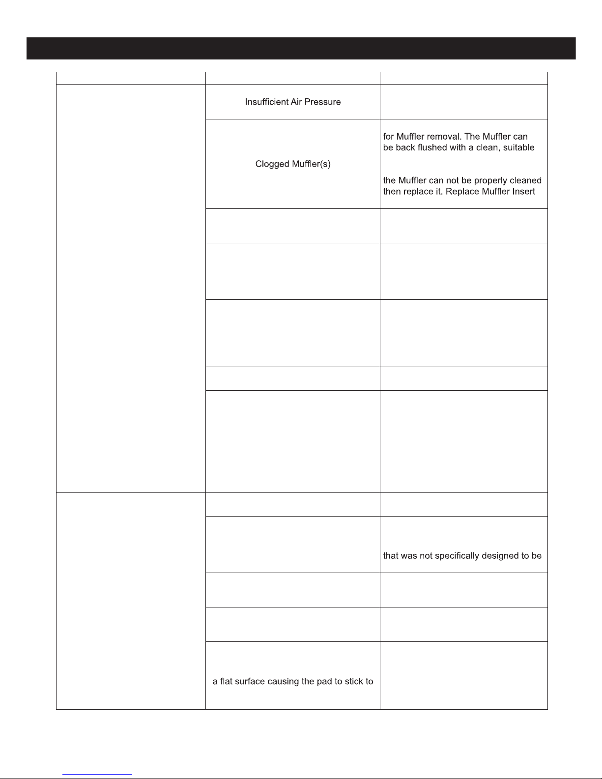
Symptom Possible Cause Solution
Low Power and/or Low Free Speed
Check air line pressure at the Inlet of
the Sander while the tool is running at
free speed. It must be 90 psig (6.2 Bar).
See the “Housing Disassembly” section
cleaning solution until all contaminates
and obstructions have been removed. If
(See the “Housing Assembly” Section).
Plugged Inlet Screen
Clean the Inlet Screen with a clean,
suitable cleaning solution. If Screen
does not come clean replace it.
One or more Worn or Broken Vanes
Install a complete set of new Vanes
(all vanes must be replaced for proper
operation). Coat all vanes with quality
pneumatic tool oil. See “Motor Disassembly” and “Motor Assembly”.
Internal air leakage in the Motor Housing
indicated by higher than normal air consumption and lower than normal speed.
Check for proper Motor alignment and
Lock Ring engagement. Check for
damaged O-Ring in Lock Ring groove.
Remove Motor Assembly and Re-Install
the Motor Assembly. See “Motor Disassembly” and “Motor Assembly”.
Motor Parts Worn
Overhaul Motor. Contact authorized
SurfPrep
TM
Service Center.
Worn or broken Spindle Bearings
Replace the worn or broken Bearings. See “Shaft Balancer and Spindle
Disassembly” and “Spindle Bearings,
AirSHIELD™ and Shaft Balancer Assembly”.
Air leakage through the Speed
Control and/or Valve Stem.
Dirty, broken or bent Valve Spring, Valve
or Valve Seat.
Disassemble, inspect and replace worn
or damaged parts. See Steps 2 and 3
in “Housing Disassembly” and Steps 2
and 3 in “Housing Assembly”.
Vibration/Rough Operation
Incorrect Pad
Only use Pad Sizes and Weights
designed for the machine.
Addition of interface pad or other material
Only use abrasive and/or interface
designed for the machine. Do not attach anything to the Sanders Pad face
used with the Pad and Sander.
Improper lubrication or buildup of foreign
debris.
Disassemble the Sander and clean in
a suitable cleaning solution. Assemble
the Sander.
Worn or broken Rear or Front Motor
Bearing(s)
Replace the worn or broken Bearings.
See “Motor Disassembly” and “Motor
Assembly”.
For vacuum machines it is possible to
have too much vacuum while sanding on
the sanding surface.
For SGV machines add extra washer(s)
to the pad spindle to increase the gap
between the pad and shroud. For CV
machines reduce vacuum through
the vacuum system and/or add extra
washer(s) to the pad.
Troubleshooting Guide
DOC 0004-SP
12
Revision 06/18/14
Page 13

SurfPrepTM Tools
571 BIRCH STREET LAKE ELSINORE, CA 92530
Tel : 951-245-4200
Fax: 951-245-4299
 Loading...