

Page 1
Operator’s MANUAL
Prod. No. 111136
111137
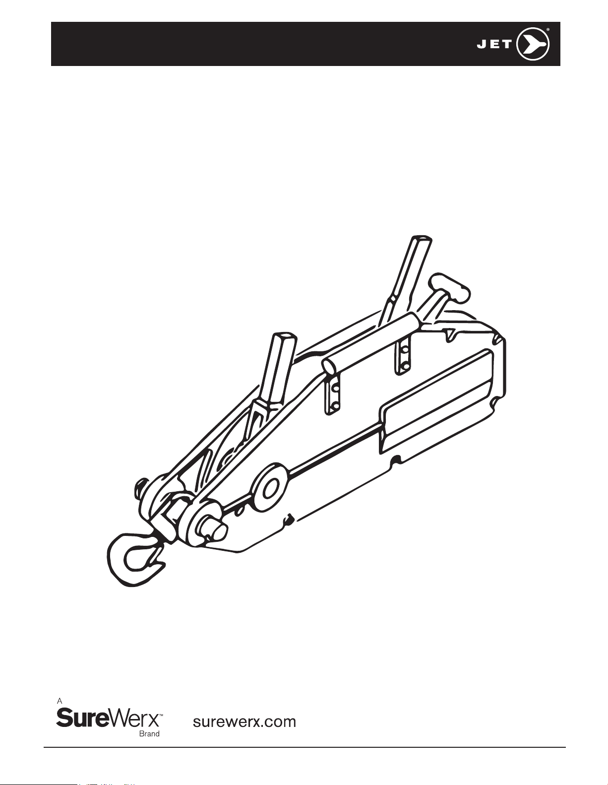
JGP SERIES GRIP PULLERS
111138
M18-MH111136 - 8
Page 2

TABLE OF CONTENTS
Waranty Policy ..............................................................2, 3
Warnings ............................................................................3
Introduction .......................................................................4
Specifications .................................................................... 4
Unpacking, Assembly and Setup ....................................4
Inserting Wire Rope ......................................................... 5
WARRANTY POLICY
JET EQUIPMENT AND TOOLS LTD.
®
) makes every effort to ensure
(JET
its products are manufactured to the
highest standards and are guaranteed
against defects in materials and
workmanship when the product is
used for the purpose for which it was
designed. This guarantee applies only
to JET products purchased new from a
JET authorized distributor.
JET product warranties are extended to
the original retail purchaser only. This
warranty does not apply to any product
showing signs of abuse, misuse,
alteration, or having been improperly
maintained or repaired.
This warranty does not cover damage
attributable to normal wear and tear.
Any JET product that fails during
normal use and is within the specified
warranty period for that product will be
repaired or replaced at JET’s discretion.
Repairs and/or replacements are
warranted as described for the specific
product only for the remainder of the
warranty period.
Repair or replacement is the exclusive
remedy for defective products under
this warranty.
Warranty is expressly in lieu of all
other warranties, including the implied
warranty or merchantability or any
implied warranty of fitness for a
particular application.
Any JET product for which there is
a warranty claim should be returned
PREPAID to an authorized JET
distributor or service centre. Authorized
Warranty Depots can be found at
surewerx.com
All warranty claims must be
accompanied by proof of purchase and
an explanation of the defect or failure.
Operation ...........................................................................5
Maintenance ......................................................................6
Troubleshooting ................................................................6
Parts Breakdown and Parts List ................................ 7 - 12
It is the customer’s responsibility to
provide this information.
JET shall not be held liable for any
consequential or incidental damages
for breach of any expressed or implied
warranty on their products. No claim
for damages or any type will be
considered, and all products are sold
with this understanding.
Any costs incurred to obtain warranty
consideration or services are the
Customer’s responsibility including
shipping and handling, travel, lost time
or lost production.
SPECIFIED WARRANTY – MATERIAL HANDLING
1 Year Limited Warranty
Chain Hoists Hand Cable Pullers
Air Hoists Lever Chain Pullers
Electric Hoists
Grip Pullers
Electric Trolleys Manual Adjustable
Trolleys
Drum Clamps Beam Clamps
Plate Clamps Blocks and Sheaves
Pallet Trucks Mobile Lift Tables
Winches
2
GENERAL INFORMATION ON JET
CHAIN HOISTS AND PULLERS
Customs Lifts – Custom lift lengths are
available, however, custom lift hoists
and pullers are NOT returnable.
CAUTION: be sure that supporting
structures and load-attaching devices
used in conjunction with hoists,
provide an adequate safety factor to
handle the rated load plus the weight
of the equipment. If in doubt, consult a
qualified structural engineer.
This equipment is not to be used for
lifting, supporting, or transporting
people, or lifting, supporting, or
transporting loads over people.
IMPORTANT: Before installation
and operation, see maintenance and
operations manual for additional
warnings, precautions and operating
instructions.
NOTE: Batteries supplied with certain
products may have been subjected to
long shelf life, resulting in low energy
or a dead battery. Please source
replacement batteries locally. Please
follow instructions in the manuals for
products using rechargeable batteries.
Dead batteries do not constitute a
warranty claim.
Page 3
Any JET product that fails during
normal use and is within the
specified warranty period for that
product will be repaired or replaced
at JET’s discretion. Repairs and/
or replacements are warranted as
described for the specific product and
only for the remainder of the original
warranty period.
Repair or replacement is the exclusive
remedy for defective product under
this warranty. Warranty is expressly in
lieu of all other warranties, including
the implied warranty of merchantability
or any implied warranty of fitness
WARNINGS
for a particular application. Any JET
product for which there is a warranty
claim should be returned PREPAID
to an authorized JET distributor or
service centre. Authorized Warranty
Depots are found at surewerx.com
ALL warranty claims must
be accompanied by proof of
purchase and an explanation of the
responsibility including shipping
and handling, travel, lost time, or lost
production.
These general instructions deal with
the normal installation, operation and
maintenance situations encountered
with the Grip Puller described herein.
The instructions should not be
interpreted to anticipate every possible
contingency or to anticipate the final
system or configuration that uses
these Grip Pullers.
These instructions include information
for a variety of hand chain hoists.
Therefore, all instructions and
information may not apply to one
specific Grip Puller. Disregard those
portions of the instructions that do
not apply.
1. Read and understand owner’s manual before
operating grip puller. Familiarize yourself with the
content of the warning label on your puller.
2. Do not exceed rated capacity.
3. Supporting structure used with this device must
provide adequate support to handle all puller
operations plus the weight of the puller and attached
equipment. If in doubt, consult a registered structural
engineer.
4. Never use handle extensions (cheaters).
5. Do not use with twisted, kinked, frayed or otherwise
damaged wire rope.
6. Do not use if grip puller is damaged or malfunctioning.
7. Do not lift people or loads over people. Always keep
people clear from load path.
8. When using grip puller to lift vertically, make sure hook
is centered under the puller.
9. Do not use as a tow line.
10. Do not use with a hook that is open or twisted, or
without safety latch.
11. Never run wire rope over a sharp edge.
12. Never leave a suspended load unattended.
13. Do not swing a suspended load.
14. Always inspect the puller before each use. Replace if
any component is damaged or malfunctioning.
15. Always use gloves when handling wire rope. Do not
wear loose clothing which can become entangled in
moving parts.
16. Do not use this grip puller in an explosive
environment.
17. Give your work undivided attention. Looking around,
carrying on a conversation and “horse-play” are
careless acts that can result in serious injury.
18. Do not operate this tool while tired or under the
influence of drugs, alcohol or any medication.
19. Failure to comply with the above warnings may result
in personal injury and/or property damage.
3
Page 4
INTRODUCTION
This manual is provided by JET covering the safe operation
and maintenance procedures for a JET Grip Puller.
This manual contains instructions on installation, safety
precautions, general operating procedures, maintenance
instructions and parts breakdown. This tool has been
designed and constructed to provide consistent, long-term
operation if used in accordance with instructions set forth in
this manual. If there are any questions or comments, please
contact either your local supplier or SureWerx. JET can also
be reached at our web site: www.surewerx.com
SPECIFICATIONS
Product No. 111136 111137 11113 8
Model No. JGP-75A JGP-150A JGP-300A
Pulling Capacity (lb) 2,860 5,720 11,440
Lifting Capacity (lb) 1,760 3,520 7,040
Force Req. to raise load (lb) 64 93 99
Dimensions (L x W x H) 16-3/4" x 2-1/2" x 9" 21-1/2" x 3-3/4" x 10-1/4" 26" x 4-1/2" x 12-1/2"
Cable Diameter 5/16" 7/16" 5/8"
Net Weight (lb) 39.7 45.2 71.6
*NOTE: The above product numbers do not include the wire rope.
The above specifications were current at the time this manual was published, but because of our policy of continuous improvement,
JET reserves the right to change specifications at any time and without prior notice, without incurring obligations.
UNPACKING
Open carton and check for shipping damage. Report any
damage immediately to your distributor and shipping agent.
Do not discard any shipping material until the Grip Puller is
assembled and operating properly.
Compare the contents of your container with the following
parts list to make sure all parts are intact. Missing parts, if any,
should be reported to your distributor. Read the instruction
manual thoroughly for assembly, maintenance and safety
instructions.
ASSEMBLY AND SETUP
Pre-Lubrication
Before proceeding with assembly, lubricate the puller as
follows: Apply a lubricating oil to the puller mechanisms while
continuously operating the reverse lever. This will help spread
the oil to the internal parts. Use special care to oil pawls and
links well. A wear resistant oil is recommended.
CAUTION: Without proper lubrication, the pawls will fail to
engage the wire rope, and the wire rope will not move.
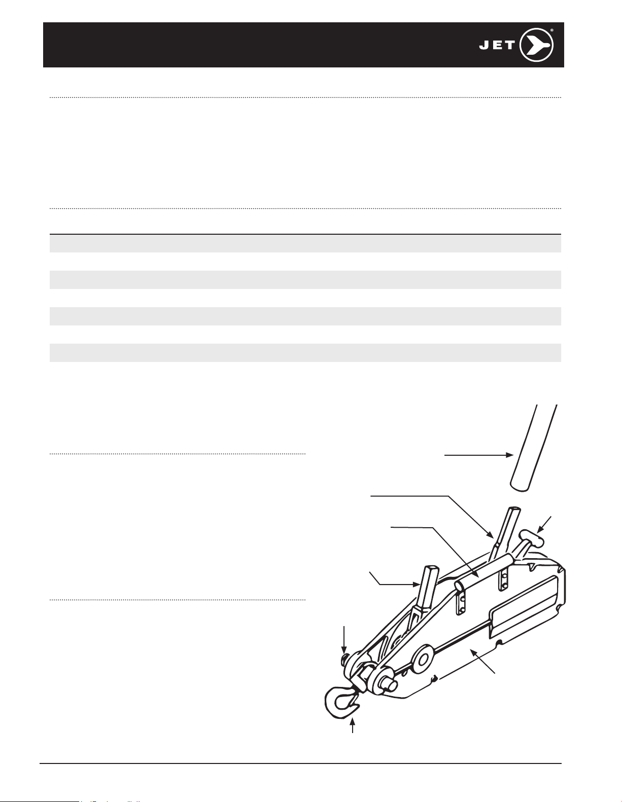
Telescoping Handle
Reverse
Lever
Hand Grip
(Contains extra shear pins)
Forward
Lever
Fastening
Bolt
Clamp
Lever
Puller Body
Swivel Hook
Figure 1.
4
Page 5
INSERTING WIRE ROPE
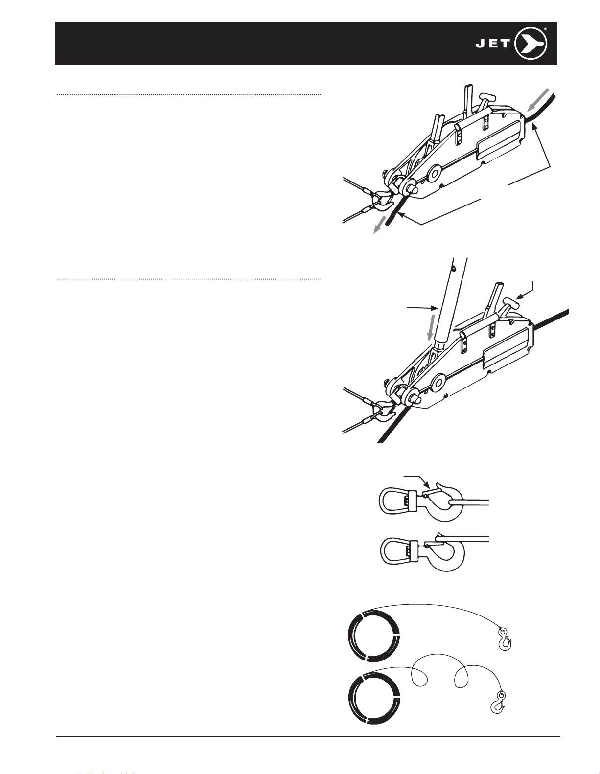
1. Release the clamp by pushing the clamp lever securely into
the notch on the puller body.
2. Insert the end of the wire rope into the rope inlet at the
rear of the puller. Feed the wire rope through until it emerges
at the other end.
3. Pull the wire rope through by hand to take up the slack and
make sure the exit point is not obstructed.
4. While keeping the wire rope taut, push down on the clamp
lever and allow it to spring back to its natural position.
This will engage the wire rope within the puller.
5. Mount the telescopic handle to either the forward or reverse
lever, according to the action desired. Rotate the handle
until it is secure on the lever.
6. The puller is now ready to operate.
Insert Wire Rope
Figure 2.
OPERATION
The grip puller uses standard ASA wire rope and may be used
in any position to lift, pull, lower or stretch heavy loads. Before
attempting operation of this product, you should become
thoroughly familiar with the warnings on page 3.
To operate the grip puller:
1. Place load cable(s) in the middle of the hook and inside the
safety latch. DO NOT attach any cables outside the safety latch
on either the puller hook or the wire rope hook.
2. Lay out the wire rope correctly without twisting. Twisting the
wire rope reduces its strength. See Figure 5.
3. To send the wire rope forward, set the telescopic handle on the
forward lever and move it back and forth.
4. To send the wire rope backward, set the telescopic handle on
the reverse lever and move it back and forth.
IMPORTANT: A shear pin is installed in the forward lever. If the
load being handled is too excessive for the puller’s capacity,
the shear pin is designed to break. If this occurs, decrease
the load or use other equipment of higher pulling capacity.
The broken shear pin is easily replaced using one of the spare
shear pins which are found within the hand grip of the pullers.
See Figure 1.
Clamp Lever
Engaged
Attach
Telescopic
Handle
Figure 3.
Safety Latch
Correct
Before storing the grip puller:
1. After use, remove the wire rope from the main body by setting
the clamp lever into the notch (disengage clamp), then pulling
the wire rope from the inlet side at the rear of the puller.
2. After the wire rope is removed, push the clamp lever out of the
notch and let it snap back to its original position. If the clamp
lever is kept in the notch for an extended time period, its spring
may become stretched.
3. Wipe off any sand or water from the puller body, including
internal mechanisms, and the wire rope, then apply oil
liberally to both.
4. Store the grip puller away from rain, dew, high humidity areas
or around acidic chemicals, which will promote rusting.
Incorrect
Figure 4.
Correct
Incorrect
Figure 5.
5
Page 6
MAINTENANCE
Make frequent and careful inspections of the puller. Make
sure puller and wire rope are sufficiently oiled, and that
they are free of any sand, dirt, dust or other obstruction or
abnormality.
Make sure hooks are not deformed and that the puller body
has not been warped or damaged.
Use care to prevent the wire rope from kinking. If the rope
is left shaped like a basket or is kinked many turns at a
single point, its strength is greatly diminished and may
result in failure.
Replace the wire rope immediately if:
• The thickness of the rope becomes less than
half of the original value due to abrasion.
• The rope exhibits basket-like shapes, kinks,
or any abnormal deformation.
• The rope is given an exceptionally heavy shock during
operation; this can fatigue the rope even if the load is
within puller capacity.
• The entire rope is napped due to many small cuts.
• The eye section (thimble) of the wire rope becomes
elliptical in shape.
• The clamp is deformed.
TROUBLESHOOTING
Trouble Probable Cause Remedy
Insufficient lubrication. Oil the puller and wire rope.
Wire rope will not move in
either direction.
Puller is dirty. Disassemble and clean out dust, dirt or other
foreign matter. Oil the puller after reassembly.
Wire rope will not advance
during normal operation, or
advances with great difficulty.
Clamp lever will not engage
the wire rope properly.
Clamp lever is not in proper
position.
Clamp lever is not in proper
position.
Pawls are not lubricated. Oil the pawl linkages properly;
Load is beyond puller capacity. Decrease load.
There is an obstruction within the
wire rope’s path.
The reverse lever is engaging the
wire rope.
Spring on clamp lever has
become stretched.
Release clamp lever from notch,
and allow it to return to engaged position.
Release clamp lever from notch,
and allow it to return to engaged position.
the pawls must engage the wire rope.
Remove the wire rope; clean and oil the puller
and the wire rope.
Check the position of the reverse lever.
Correct as needed.
Replace spring.
6
Page 7
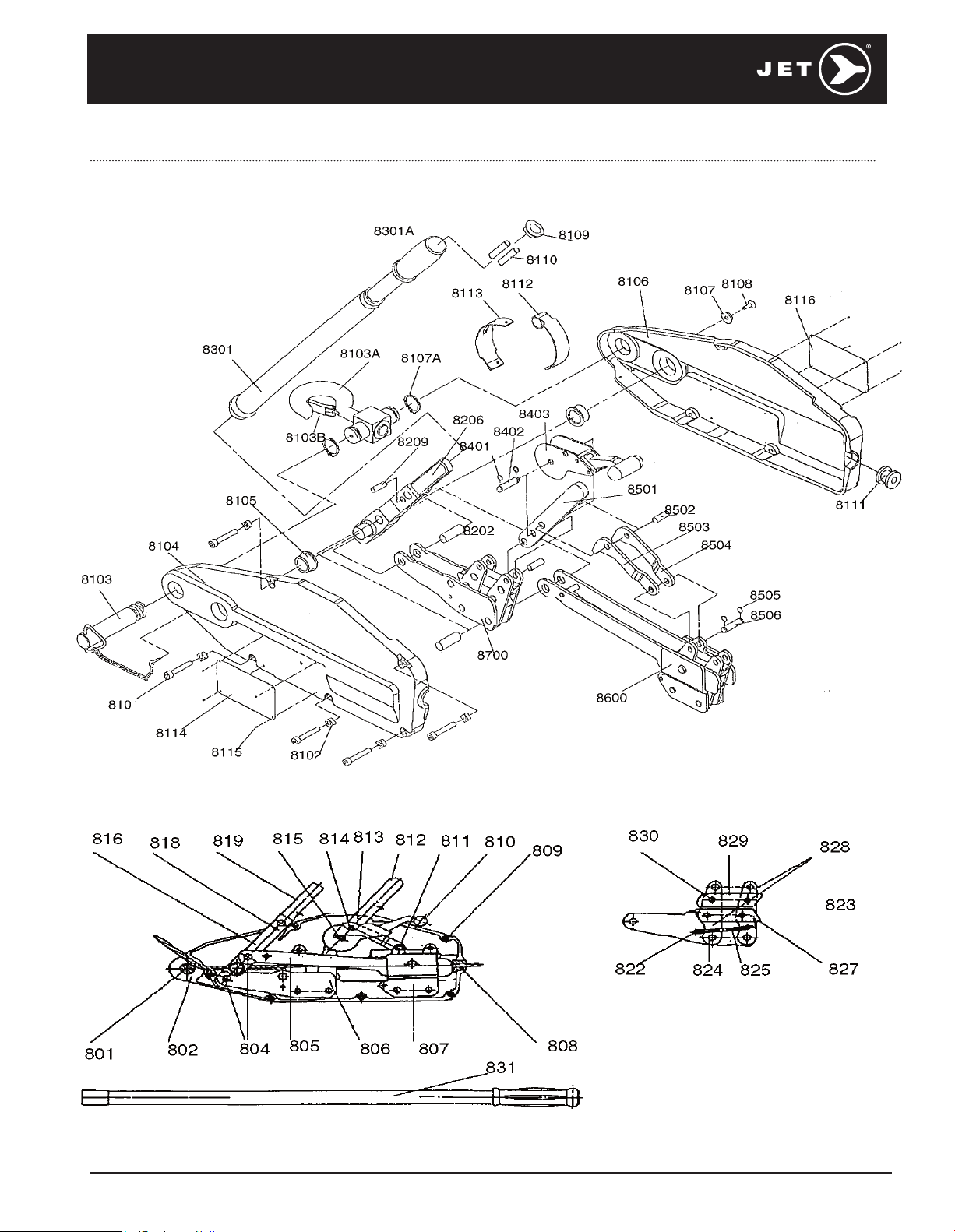
JGP75A | 3/4 T GRIP PULLER PARTS BREAKDOWN | PROD. NO. 111136
7
Page 8
JGP75A | 3/4 T GRIP PULLER PARTS LIST | PROD. NO. 111136
REF. PART NUMBER DESCRIPTION REQ. REF. PART NUMBER DESCRIPTION REQ.
801 PWC-SGP75-801 SGP75 ANCHOR PIN 1
802 PWC-SGP75-802 SGP75 CASE LEFT/RIGHT ALUMINUM 2
804 PWC-SGP75-804 SGP75 CRANK AXLE 1
805 PWC-SGP75-805 SGP75 CONNECTING ROD 2
806 PWC-SGP75-806 SGP75 FRONT JAW BLOCK 1
807 PWC-SGP75-807 SGP75 REAR JAW BLOCK 1
808 PWC-SGP75-808 SGP75 ROPE GUIDE 1
809 PWC-SGP75-809 SGP75 CASE BOLT 6
810 PWC-SGP75-810 SGP75 RELEASE HANDLE 1
811 PWC-SGP75-811 SGP75 RELEASE CONNECTING
ROD AXLE
812 PWC-SGP75-812 SGP75 REVERSE LEVER 1
813 PWC-SGP75-813 SGP75 CONNECTING ROD LEFT SIDE 1
814 PWC-SGP75-814 SGP75 CONNECTING AXLE 1
815 PWC-SGP75-515 SGP75 RELEASE HANDLE PIN 1
816 PWC-SGP75-816 SGP75 SHAKE ROD W/819
OPERATING LEVER
818 PWC-SGP75-818 SGP75 SHEAR PIN 1
818 PWC-SGP75-18A SGP75 SHEAR PIN 7.5 MM 1
819 PWC-SGP75-819 SGP75 OPERATING LEVER W/816
SHAKE ROD
822 PWC-SGP75-822 SGP75 SPRING 1
823 PWC-SGP75-823 SGP75 CLAMP PLATE W/828
LONG CLAMP PLATE
824 PWC-SGP75-824 SGP75 CLAMP PLATE AXLE 1
825 PWC-SGP75-825 SGP75 SPRING HOUSING 1
827 PWC-SGP75-827 SGP75 LOWER JAW 2
828 PWC-SGP75-828 SGP75 LONG CLAMP PLATE 2
829 PWC-SGP75-829 SGP75 UPPER JAW 2
830 PWC-SGP75-830 SGP75 JAW AXLE 4
831 PWC-SGP75-831 SGP75 TELESCOPIC HANDLE 1
8101 PWC-SGP75-809 SGP75 CASE BOLT 6
8102 PWC-SGP75-8102 SGP75A NUT 6
8103 PWC-SGP75-801 SGP75 ANCHOR PIN 1
8104 PWC-SGP75A-8104 SGP75A CASE LEFT METAL 1
8105 PWC-SGP75-8105 SGP75A BUSHING FOR SHAKE ROD 2
8106 PWC-SGP75A-8106 SGP75A CASE RIGHT METAL 1
8107 PWC-SGP75-8107 SGP75 WASHER 1
1
1
1
2
8108 PWC-SGP75-8108 SGP75 SCREW BOLT 1
8109 PWC-SGP75-8109 SGP75A COVER 1
8110 PWC-SGP75-818 SGP75 SHEAR PIN 1
8111 PWC-SGP75-808 SGP75 ROPE GUIDE 1
8112 PWC-SGP75-8112 SPG75A UPPER DUST SHIELD 1
8113 PWC-SGP75-8113 SPG75A LOWER DUST SHIELD 1
8114 PWC-SGP75-8114 SGP75A NAME PLATE 1
8115 PWC-SGP75-8115 SGP75A RIVET 8
8116 PWC-SGP75-8116 SGP75A INSTRUCTION PLATE 1
8202 PWC-SGP75-804 SGP75 CRANK AXLE 2
8206 PWC-SGP75-816 SGP75 SHAKE ROD W/819
OPERATING LEVER
8206 PWC-SGP75-819 SGP75 OPERATING LEVER W/816
SHAKE ROD
8209 PWC-SGP75-818 SGP75 SHEAR PIN 1
8301 PWC-SGP75-831 SGP75 TELESCOPIC HANDLE 1
8401 PWC-SGP75-8401 SGP75A SNAP RING 2
8402 PWC-SGP75-815 SGP75 RELEASE HANDLE PIN 1
8403 PWC-SGP75-810 SGP75 RELEASE HANDLE 1
8501 PWC-SGP75-812 SGP75 REVERSE LEVER 1
8502 PWC-SGP75-814 SGP75 CONNECTING AXLE 1
8503 PWC-SGP75-813 SGP75 CONNECTING ROD LEFT SIDE 2
8504 PWC-SGP75-8504 SGP75A CONNECTING ROD
RIGHT SIDE
8505 PWC-SGP75-8505 SGP75A SNAP RING 2
8506 PWC-SGP75-811 SGP75 RELEASE CONNECTING
ROD AXLE
8600 PWC-SGP75-8600 SGP75A REAR JAW BLOCK
ASSY SET
8700 PWC-SGP75-8700 SGP75A FRONT JAW BLOCK ASSY 1
8103A PWC-SGP75-8103 SGP75A TOP HOOK 1
8103B PWC-SGP75A-SAF SGP75A SWIVEL HOOK SAFETY
LATCH KIT
8107A PWC-SGP75-8107A SGP75A SNAP RING 2
8301A PWC-SGP75-8301A SGP75 TELESCOPIC HANDLE
RUBBER GRIP
** PELJG75BCP JG75 WIRE ROPE LOWER HOOK 1
** PELJG75SAF JG75 WIRE ROPE LOWER HOOK
LATCH KIT
1
1
1
1
1
1
1
1
Note: To determine if the puller is old or new style, establish if the unit has a top hook (new) or a pin (old).
See reference numbers 8103 and 8103A located on parts breakdown, for further clarification.
8
Page 9
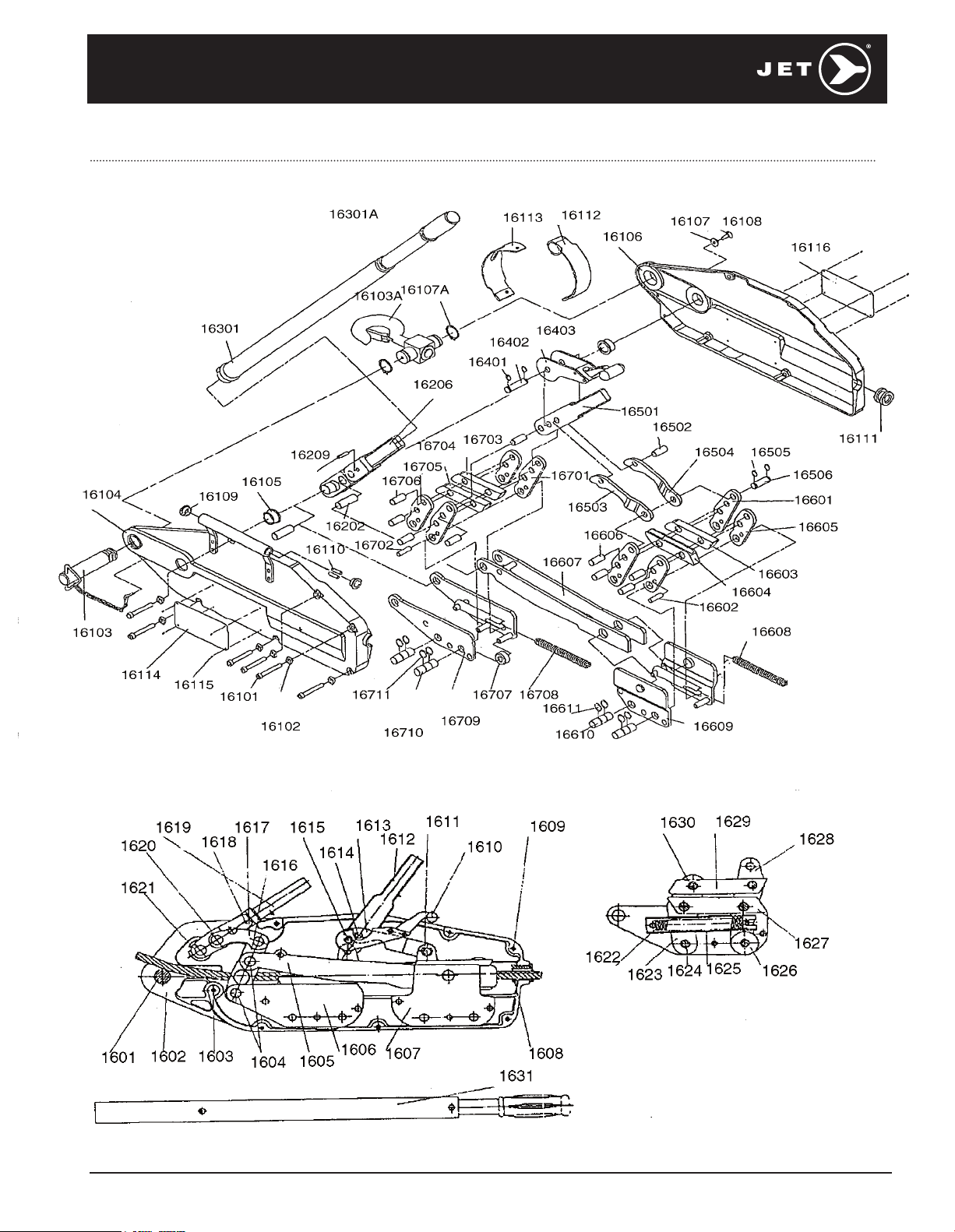
JGP150A | 1-1/2 T GRIP PULLER PARTS BREAKDOWN | PROD. NO. 111137
9
Page 10
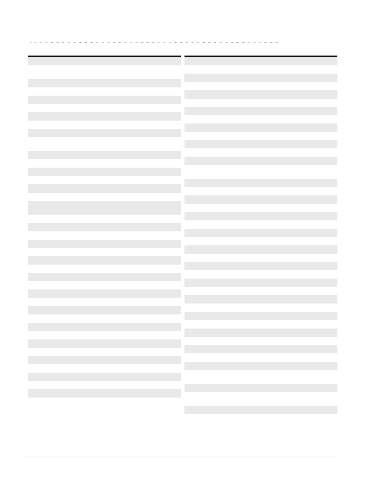
JGP150A | 1-1/2 T GRIP PULLER PARTS LIST | PROD. NO. 111137
REF. PART NUMBER DESCRIPTION REQ. REF. PART NUMBER DESCRIPTION REQ.
1601 PWC-SGP150-1601 SGP150 ANCHOR PIN 1
1602 PWC-SGP150-1602 SGP150 CASE LEFT/RIGHT
ALUMINUM
1604 PWC-SGP150-1604 SGP150 CRANK AXLE 1
1605 PWC-SGP150-1605 SGP150 CONNECTING ROD 2
1606 PWC-SGP150-1606 SGP150 FRONT JAW BLOCK 1
1607 PWC-SGP150-1607 SGP150 REAR JAW BLOCK 1
1608 PWC-SGP150-1608 SGP150 ROPE GUIDE 1
1609 PWC-SGP150-1609 SGP150 CASE BOLT 6
1610 PWC-SGP150-1610 SGP150 RELEASE HANDLE 1
1611 PWC-SGP150-1611 SGP150 RELEASE CONNECTING
ROD AXLE
1612 PWC-SGP150-1612 SGP150 REVERSE LEVER 1
1613 PWC-SGP150-1613 SGP150 CONNECTING ROD 2
1614 PWC-SGP150-1614 SGP150 CONNECTING AXLE 1
1615 PWC-SGP150-1615 SGP150 RELEASE HANDLE PIN 1
1616 PWC-SGP150-1616 SGP150 SHAKE ROD USE 1619 1
1618 PWC-SGP150-18 SGP150 SHEAR PIN 1
1619 PWC-SGP150-1619 SGP150 OPERATING LEVER
C/W 1616
1622 PWC-SGP150-1622 SGP150 SPRING 2
1623 PWC-SGP150-1623 SGP150 CLAMP PLATE 1
1624 PWC-SGP150-1624 SGP150 CLAMP PLATE AXLE 1
1625 PWC-SPC150-1625 SGP150 SPRING HOUSING 2
1626 PWC-SGP150-1626 SGP150 SUPPORT WHEEL 1
1627 PWC-SGP150-1627 SGP150 LOWER JAW 2
1628 PWC-SGP150-1628 SGP150 LONG CLAMP PLATE 2
1629 PWC-SGP150-1629 SGP150 UPPER JAW 2
1630 PWC-SGP150-1630 SGP150 JAW AXLE 4
1631 PWC-SGP150-1631 SGP150 TELESCOPIC HANDLE 1
16101 PWC-SGP150-1609 SGP150 CASE BOLT 6
16102 PWC-SGP15-16102 SGP150A CASE NUT 6
16103 PWC-SGP150-1601 SGP150 ANCHOR PIN 1
16104 PWC-SGP15-16104 SGP150A CASE LEFT METAL 1
16105 PWC-SGP15-16105 SGP150A BUSH FOR SHAKE ROD 2
16106 PWC-SGP15-16106 SGP150A CASE RIGHT METAL 1
16107 PWC-SGP15-16107 SGP150A WASHER 1
16109 PWC-SGP15-16109 SGP150A PLASTIC PLUG 1
16111 PWC-SGP150-1608 SGP150 ROPE GUIDE 1
16112 PWC-SGP15-16112 SPG150A UPPER DUST SHIELD 1
16113 PWC-SGP15-16113 SPG150A LOWER DUST SHIELD 1
16114 PWC-SGP15-16114 SGP150A NAME PLATE 1
16115 PWC-SGP15-16115 SGP150A RIVET 8
2
1
1
16116 PWC-SGP15-16116 SGP150A INSTRUCTION PLATE 1
16202 PWC-SGP150-1604 SGP150 CRANK AXLE 1
16206 PWC-SGP150-1616 SGP150 SHAKE ROD USE 1619 1
16209 PWC-SGP150-18 SGP150A SHEAR PIN 1
16301 PWC-SGP150-1631 SGP150 TELESCOPIC HANDLE 1
16401 PWC-SGP15-16401 SGP150A SNAP RING 2
16402 PWC-SGP150-1615 SGP150 RELEASE HANDLE PIN 1
16403 PWC-SGP150-1610 SGP150 RELEASE HANDLE 1
16501 PWC-SGP150-1612 SGP150 REVERSE LEVER 1
16502 PWC-SGP150-1614 SGP150 CONNECTING AXLE 1
16503 PWC-SGP150-1613 SGP150 CONNECTING ROD 1
16504 PWC-SGP150-1613 SGP150 CONNECTING ROD 1
16505 PWC-SPC15-16505 SGP150A SNAP RING 2
16506 PWC-SGP150-1611 SGP150 RELEASE CONNECTING
ROD AXLE
16601 PWC-SGP15-16601 SGP150A LONG CLAMP PLATE 2
16602 PWC-SGP15-16602 SGP150A CLAMP PLATE PIN 1
16603 PWC-SGP15-16603 SGP150A UPPER JAW 1
16604 PWC-SGP15-16604 SGP150A LOWER JAW 1
16605 PWC-SGP15-16605 SGP150A CLAMP PLATE 2
16606 PWC-SGP15-16606 SGP150A JAW AXLE 4
16607 PWC-SGP150-1605 SGP150 CONNECTING ROD 2
16608 PWC-SGP15-16608 SGP150A SPRING 1
16609 PWC-SGP150-1607 SGP150 REAR JAW BLOCK 1
16610 PWC-SGP15-16610 SGP150A CLAMP PLATE AXLE 2
16611 PWC-SGP15-16611 SGP150A SNAP RING 4
16701 PWC-SGP150-1628 SGP150 LONG CLAMP PLATE 2
16702 PWC-SGP15-16702 SGP150A CLAMP PLATE PIN 1
16703 PWC-SGP150-1629 SGP150 UPPER JAW 2
16704 PWC-SGP150-1627 SGP150 LOWER JAW 2
16705 PWC-SGP150-1623 SGP150 CLAMP PLATE 1
16706 PWC-SGP150-1630 SGP150 JAW AXLE 4
16707 PWC-SPC150-1625 SGP150 SPRING HOUSING 2
16708 PWC-SGP150-1622 SGP150 SPRING 2
16709 PWC-SGP150-1606 SGP150 FRONT JAW BLOCK 1
16710 PWC-SGP15-16710 SGP150A CLAMP PLATE AXLE 2
16711 PWC-SGP15-16711 SGP150A SNAP RING 4
16103A PWC-SGP15-16103 SGP150 TOP HOOK 1
16103B PWC-SGP150A-SAF SGP150A SWIVEL HOOK SAFETY
LATCH KIT
16107A PWC-SGP15-16107A SGP150A SNAP RING 2
16301A PWC-SGP15-16301A SGP150A TELESCOPIC HANDLE
RUBBER GRIP
1634 PWC-SGP150-1634 TOP HOOK 1
1
1
1
10
Note: To determine if the puller is old or new style, establish if the unit has a top hook (new) or a pin (old).
See reference numbers 16103 and 16103A located on parts breakdown, for further clarification.
Page 11
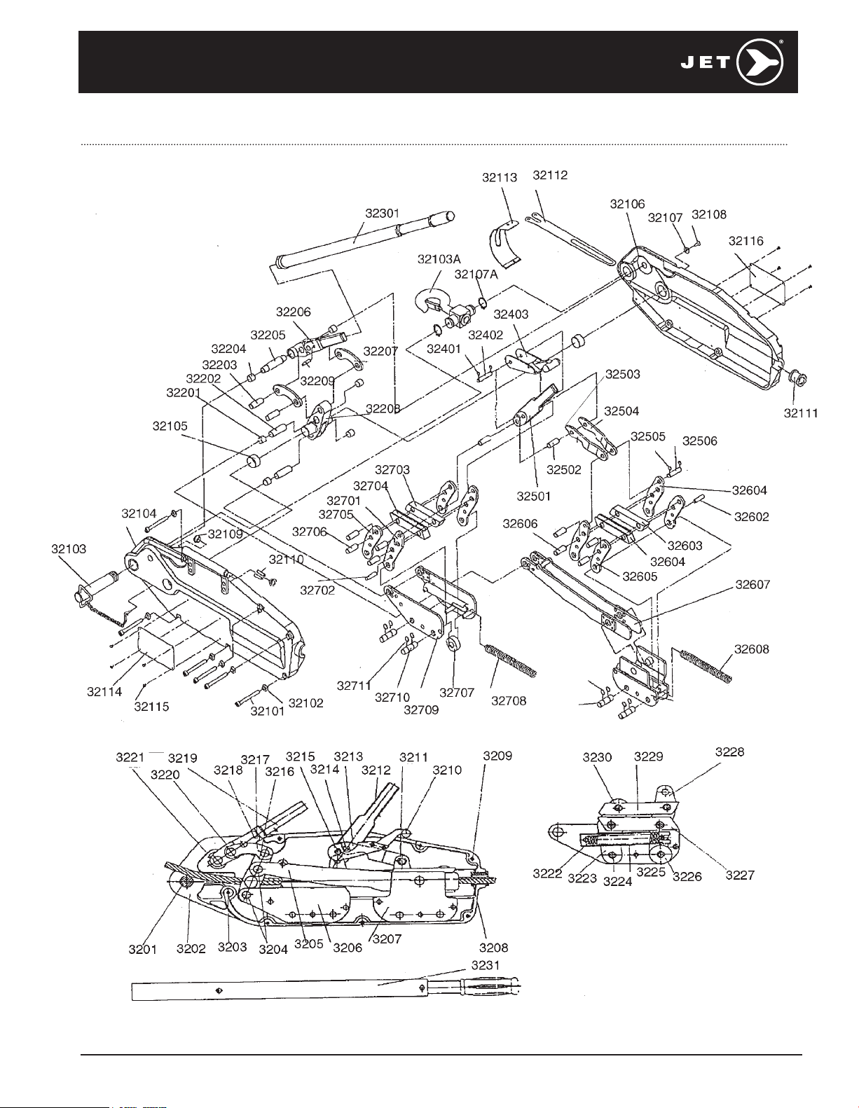
JGP300A | 3 T GRIP PULLER PARTS BREAKDOWN | PROD. NO. 111138
11
Page 12

JGP300A | 3 T GRIP PULLER PARTS LIST | PROD. NO. 111138
REF. PART NUMBER DESCRIPTION REQ. REF. PART NUMBER DESCRIPTION REQ.
3201 PWC-SGP300-3201 ANCHOR PIN 1
3202 PWC-SGP300-3202 CASE LEFT/RIGHT SIDE 2
3203 PWC-SGP300-3203 LONG HEX HEAD CASE BOLT 1
3204 PWC-SGP300-3204 CRANK AXLE 1
3205 PWC-SGP300-3205 CONNECTING ROD 1
3206 PWC-SGP300-3206 FRONT JAW BLOCK 1
3207 PWC-SGP300-3207 REAR JAW BLOCK 1
3208 PWC-SGP300-3208 ROPE GUIDE 1
3209 PWC-SGP300-3209 HOUSING SCREW BOLT 6
3210 PWC-SGP300-3210 RELEASE HANDLE 1
3211 PWC-SGP300-3211 RELEASE CONNECTING ROD AXLE 1
3212 PWC-SGP300-3212 REVERSING LEVER 1
3213 PWC-SGP300-3213 CONNECTING ROD 2
3214 PWC-SGP300-3214 CONNECTING AXLE 1
3215 PWC-SGP300-3215 RELEASE HANDLE PIN 1
3216 PWC-SGP300-3216 SHAKE ROD 1
3217 PWC-SGP300-3217 CONNECTING ROD 1
3218 PWC-SGP150-18 SHEAR PIN 1
3219 PWC-SGP300-3219 OPERATING LEVER 1
3220 PWC-SGP300-3220 CONNECTING ROD AXLE 1
3221 PWC-SGP300-3221 OPERATING HANDLE AXLE 1
3222 PWC-SGP300-3222 SPRING 1
3223 PWC-SGP300-3223 CLAMP PLATE 2
3224 PWC-SGP300-3224 CLAMP PLATE AXLE 2
3225 PWC-SGP300-3225 SPRING HOUSNG 1
3226 PWC-SGP300-3226 SUPPORT WHEEL 1
3227 PWC-SGP300-3227 LOWER JAW 1
3228 PWC-SGP300-328 LONG CLAMP PLATE 2
3229 PWC-SGP300-3229 UPPER JAW 1
3230 PWC-SGP300-3230 JAW AXLE 4
3231 PWC-SGP300-3231 TELESCOPE HANDLE 1
32101 PWC-SGP300-3209 HOUSING SCREW BOLT 6
32102 PWC-SGP30-32102 NUT 1
32103 PWC-SGP300-3201 ANCHOR PIN 1
32104 PWC-SGP30-32104 HOUSING (LEFT SIDE) 1
32105 PWC-SGP30-32105 BUSH FOR SHAKE ROD
NO LONGER USED
32106 PWC-SGP30-32106 HOUSING (RIGHT SIDE) 1
32107 PWC-SGP75-8107 WASHER 1
32108 PWC-SGP75-8108 SCREW BOLT 1
32109 PWC-SGP30-32109 COVER 1
32110 PWC-SGP150-18 SPARE SHEAR PIN 2
32111 PWC-SGP300-3208 ROPE GUIDE 1
32112 PWC-SGP30-32112 UPPER DUST PROOF 1
32113 PWC-SGP30-32113 LOWER DUST PROOF 1
32114 PWC-SGP30-32114 NAMEPLATE 1
32115 PWC-SGP15-16115 RIVET 8
32116 PWC-SGP30-32116 INSTRUCTION PLATE 1
32201 PWC-SGP300-32201 BUSH FOR CRANK AXLE
NO LONGER USED
32202 PWC-SGP300-3204 CRANK AXLE 2
32203 PWC-SGP300-3220 CONNECTING ROD AXLE 2
32204 PWC-SGP30-32204 BUSH FOR OPERATING HANDLE AXLE 2
32205 PWC-SGP300-3221 OPERATING HANDLE AXLE 1
32206 PWC-SGP300-3219 OPERATING LEVER 1
32207 PWC-SGP300-3217 CONNECTING ROD 1
32208 PWC-SGP300-3216 SHAKE ROD 1
32209 PWC-SGP150-18 SHEAR PIN 1
32301 PWC-SGP300-3231 TELESCOPE HANDLE 1
32401 PWC-SGP30-32401 SNAP RING 2
32402 PWC-SGP300-3215 RELEASE HANDLE PIN 1
32403 PWC-SGP300-3210 RELEASE HANDLE 1
32501 PWC-SGP300-3212 REVERSING LEVER 1
32502 PWC-SGP300-3214 CONNECTING AXLE 1
32503 PWC-SGP300-3213 CONNECTING ROD(LEFT SIDE) 1
32504 PWC-SGP300-3213 CONNECTING ROD(RIGHT SIDE) 1
32505 PWC-SGP30-32505 SNAP RING 2
32506 PWC-SGP300-3211 RELEASE CONNECTING ROD AXLE 1
32601 PWC-SGP30-32601 LONG CLAMP PLATE 2
32602 PWC-SGP30-32602 CLAMP PLATE PIN 1
32603 PWC-SGP30-32603 UPPER JAW 1
32604 PWC-SGP30-32604 LOWER JAW 1
32605 PWC-SGP30-32605 CLAMP PLATE 2
32606 PWC-SGP30-32606 JAW AXLE 4
32607 PWC-SGP300-3205 CONNECTING ROD 1
32608 PWC-SGP30-32608 SPRING 1
32609 PWC-SGP300-3207 REAR JAW BLOCK 1
32610 PWC-SGP30-32610 CLAMP PLATE AXLE 2
32611 PWC-SGP30-32611 SNAP RING 4
32701 PWC-SGP300-328 LONG CLAMP PLATE 2
32702 PWC-SGP30-32702 CLAMP PLATE PIN 1
32703 PWC-SGP300-3229 UPPER JAW 1
32704 PWC-SGP300-3227 LOWER JAW 1
32705 PWC-SGP300-3223 CLAMP PLATE 2
32706 PWC-SGP300-3230 JAW AXLE 4
32707 PWC-SGP300-3226 SUPPORT WHEEL 1
32708 PWC-SGP300-3222 SPRING 1
32709 PWC-SGP300-3206 FRONT JAW BLOCK 1
32710 PWC-SGP300-3224 CLAMP PLATE AXLE 2
32711 PWC-SGP30-32711 SNAP RING 4
32103A PWC-SGP3032103A SWIVEL HOOK(FOR A TYPE) 1
32103B PWC-SGP300A-SAF SAFTEY LATCH W HARDWARE 1
32107A PWC-SGP3032107A SNAP RING(FOR A TYPE) 2
PWC-SGP300-3234 SWIVEL HOOK 1
12
 Loading...