


This machi ne has been engine ered to our own rigid safety and performance standards. It
has been de signed to comply wi th sanitation and health guideli nes recommended by the
Automatic Merchandising Health-Industry Council (AMHIC) and it conforms with all
other NAMA safety recommendations.
This machi n e has been manufactured in accor dance with the s afety standards of both
Underwriter’s Labo ratories and the Canadian Standards Association. To maintain this
degree of safety and to continue to achieve the level of performance built in to this
machine, it is important that installation and maintenance be performed so as to not al ter
the original construction or wiring and that replac em ent parts are as specified in the Parts
Manual. Your investm ent in this equip me n t will be protect ed by using this Setup and
Operato r’s Guide, the Programming Gui de, and the Parts Manual in your operation, service and mai ntenance work. By following prescribed procedures, machine performance
and safe ty w ill be preserved.
Crane Merchandising Systems Parts and Support
Phone Numbers:
Parts: 1-800-621-7278
Service: 1-800-628-8363

Hot Drink Center II Set-Up Manual
Table of Contents
Title Page
SPECIFICATIONS ............................................................................................ 1
MAJOR PA RTS ..... .. .. ........ .. ... .............. ... .. ...................... .. ... .............. ... .. .......... 4
CONTROLS AND INDICATORS .................................... ............... .. .............. 8
INITIAL SET-UP ............................................................................................. 14
Location Preparation ................................................................................... 14
Water Requirements ................................................................................ 15
Positioning the Merchandiser...................................................................... 16
Connecting Everything................................................................................ 16
Connect the Mercha ndiser to the Water Supply:........................ .. ....... 16
Connec t the Me r ch an d i s er to the El ectrica l P o w er Su pp l y : ...... .. ... ..... 16
Final Mechanical Preparation...................................................................... 16
Level the Merchandiser:....................................................................... 16
Mount the Base Plate: .......................................................................... 17
Set Up the Menu Assembly ................................................................. 18
Install the Water Filter Cartridge: ........................................................ 19
Load the Optional Filter Paper:............................................................ 22
Install the Optional Coin Box Lock ..................................................... 24
Load the Coin Mechanism ................................................................... 24
Fill the Tank:........................................................................................ 24
Fill the Canisters: ................................................................................. 25
Load Cup s: ... .. ............... .. ... .............. ... .. ...................... ... .. ............... .. .. . 26
Tell the Machine About the Cup Size(s):............................................. 27
Test the Machine:................................................................................. 28
ADJUSTMENTS AND MINOR MAINTENANCE............................... ....... 29
Water V al v e A d ju st m e n t........... .. ... .............. ... .. ............... .. ... .............. ... .. ... 29
Cup Mechanism Adjustment....................................................................... 30
Grinde r A d ju s t ment.... ........ .. .. ........ .. ... .............. ... .. ............... .. .. ............... .. . 31
Disengaging the Grinder ............................................................................. 32
Canister Installation..................................................................................... 32
Removing POP to Servi ce fluorescent lights, Starters and ballas ts.......... .. 33
SANITATION................................................................................................... 34
Basics .......................................................................................................... 34
Clean th e H o t W at er Ta nk.. .. ...................... .. ... .............. ... .. ...................... .. . 36
Sanitation Procedures.................................................................................. 36
Food-Contact Parts .................................................................................. 36
Non Food-Contact Parts .......................................................................... 37
Brewer C le an in g.. .. ............... .. ... .............. ... .. ............... .. ... ...................... .. .. . 38
Overall Cleaning ......................................................................................... 44
Preventive Maintenance Cleaning............................................................... 44
6730013 i
February, 2003

Hot Drink Center II Set-Up Manual
Notes . . .
________________________________________________________________
________________________________________________________________
________________________________________________________________
________________________________________________________________
________________________________________________________________
________________________________________________________________
________________________________________________________________
________________________________________________________________
________________________________________________________________
________________________________________________________________
________________________________________________________________
________________________________________________________________
________________________________________________________________
________________________________________________________________
________________________________________________________________
________________________________________________________________
________________________________________________________________
________________________________________________________________
________________________________________________________________
________________________________________________________________
________________________________________________________________
________________________________________________________________
ii 6730013
February, 2003

Hot Drink Center II Set-Up Manual
SPECIFICATIONS
SPECIFICA TIONS COMMON TO ALL MACHINES
DIMENSIONS 72" (183 cm) high
38.12" (97 cm) w ide
28.5" (72 cm ) deep
WEIGHT 570 lbs (258.5 kg)
WATER REQUIREMENTS Mini m u m : 20 psi (13 7. 8 kPa)
Maximum: 80 psi (551.2 kPa)
AMBIENT TEMPERATURE Minimum: 41× F (5× C)
Maximum: 90× F (32× C)
OPERA TING ENVIRONMENT For indoor use only
CUP CAPACITIES
(APPROXIMATE)
CANISTER CAPACITIES
(APPROXIMATE)
FILTER PAP ER CAPACITY 2400 vends per roll
MODEL 673 FRESH BREW Up to elev en s elect i ons of f re sh brew regul ar and
MODEL 675 FREEZE DRIED Up to eleven selections of freeze dried regular
MODEL 677 FRESH BREW
WITH
BEAN GRINDER
12 oz cups = 600
14 oz cups = 530
16 oz cups = 380
20 oz cups = 358
Regular coffee beans - 14 lbs
Ground coffee - 13 lbs
Freeze dry coffee - 2 lbs
Decaf coffee beans - 9.5 lbs
Ground decaf coffee - 9 lbs
Freeze dry decaf - 2 lbs
Chocolate - 10 lbs
Soup - 6.7 lbs
Sugar - 11 lbs
Lightener - 4.5 lbs
Sugar substitute - 4 lbs
Tea (freeze dr y) - 1.5 lbs
6th and 7th products (fre eze dry) - 6 lbs each
PRODUCT OPTIONS
decaf coffee, freeze dried regular and decaf coffee, fresh brew and f reeze dried tea, soup, chocolate, cappuccino, espresso, caff è latte, and two
blended drinks.
coffee, decaf coffee, tea, soup, chocolate, cappuccino, espresso, caffè latte, and two blended
drinks.
Up to nin e sel ect ions of fres h gr ou nd and b re wed
regular a nd d eca f cof fee , free ze dri ed regul ar a nd
decaf cof fee, fresh brew and freeze dried tea,
soup, chocolate, cappuccino, espresso, caffè
latte, and two blended drink s.
6730013 1
February, 2003

Hot Drink Center II Set-Up Manual
SPECIFICATIONS COMMON TO ALL MACHINES (Continued)
OPTIONS AND ACCESSORIES
OPTIONS Coin box lock
Base grille kit
Autom a ti c de li ve ry door
Flex Ace door lock and key
Van Door lo ck and key
Sugar substitute kit
6th product kit
Cup/mug elec tronic sensor ( cup hold switch kit)
Snap-on ingredient canister
extension sleeves (4 tall)
Everpure water filter system
CUNO water filter system
Debit ca rd va li da to r
Free vend key switch
Data printer kit
Ingredient rinse tr ay
2 6730013
February, 2003

Hot Drink Center II Set-Up Manual
SPECIFICA TIONS UNIQUE TO 115 VOLT MACHINES
ELECTRICAL 115 Volts AC
60 Hertz
16 Amps
Single phase
OPTIONS AND ACCESSORIES
COIN MECHANISM MARS TRC-6000
COINTRON 3000
MARS TRC-6010XV (24 V)
Maka/Conlux Model USPX-004 (24 V)
Coin Accept ors Model 9302-LF (2 4 V )
BILL VALIDATORS MARS VFM1 pulse
MARS VFM3 serial
MAKA pulse
COINCO
SPECIFICATIONS UNIQUE TO 220 - 240 VOLT MACHINES
ELECTRICAL 220-240 Volts AC
50 Hertz
10 Amps
2 kW
Single phase
OPTIONS AND ACCESSORIES
COIN MECHANISM Executiv e coin mechanism interfac e
6730013 3
February, 2003
Hot Drink Center II Set-Up Manual
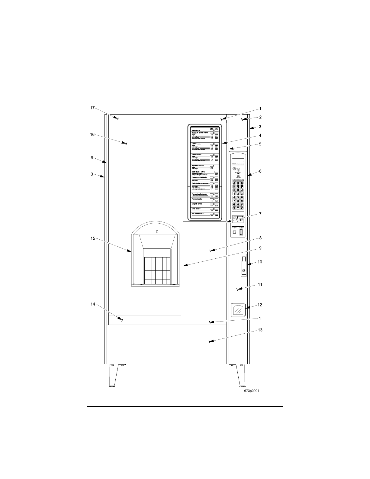
MAJOR PARTS
The diagram s on the following pages will acquaint you with the major parts of the Ho t
Drink Center. For more detailed information, please consult your PARTS MANUAL. If
you do not hav e a PARTS MANUAL, contact National Vendors Parts Department.
4 6730013
Door Assembly - Exterior
February, 2003

Hot Drink Center II Set-Up Manual
6730013 5
February, 2003
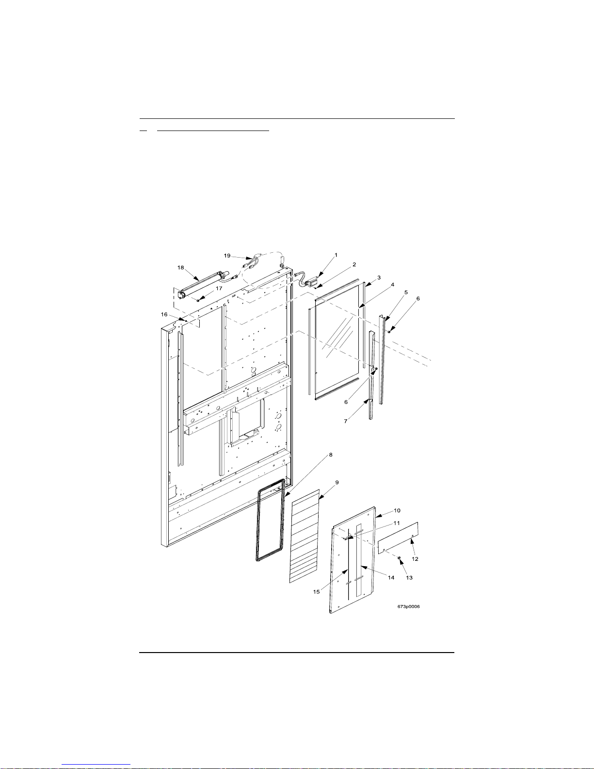
Door Assembly - Interior

Hot Drink Center II Set-Up Manual
6 6730013
Cabinet Assembly Interio r - Part 1
February, 2003

Hot Drink Center II Set-Up Manual
6730013 7
February, 2003
Cabinet Assembly Interio r - Part 2

Hot Drink Center II Set-Up Manual
CONTROLS AND INDICATORS
POWER PANEL. You may have one of three power panels, depending upon
where you live. The controls are fundamentally the same, however.
Circuit Breakers and Fuses.
Circuit breakers and fuses protect the merchandiser against failures in the power supply or any of the el ec trical components. If
a circuit breaker trips and cannot be reset, or if a fuse repeat edly blows, contact a
field service representative.
Back Side of U.S./ Canada Power Control Panel.
The circuit board mounted
on the rear of th e U.S. an d Canadi an power c ontrol pa nel is a dc powe r suppl y for
the coin mechanism. A fuse protects the board circuitr y i n th e event of a coin
mechanism solenoid failure. If the coin mechanis m is not working, check this
fuse. If the fuse is blown, a bad coin mechanism solenoid could be at fault .
Main Power Switch.
This is the main ON/OFF switch for the merchandiser.
WARNING
To protect against electrical shocks and pos s ible damage to the
machine, turn thi s switch OFF when performing any maintenance on the merchandiser.
LABEL
I
O
MAIN
POWER
SWITCH
ELECTRONICS
BREAKER
8 6730013
626P0005
Power Control Panel (Fran ce/Germany/Spain)
February, 2003

LABEL
Hot Drink Center II Set-Up Manual
MAIN
ON
OFF
Power Control Pane l (U.S./Canada)
POWER
SWITCH
MAIN
CIRCUIT
BREAKER
LOW VOLTAGE
CIRCUIT BREAKER
626P0006
6730013 9
February, 2003
Back Side of U.S./Canada Power Panel

Hot Drink Center II Set-Up Manual
ON
MAIN POWER
SWITCH
ELECTRONICS
CIRCUIT BREAKER
LABEL
OFF
MOUNTING STUDS
FOR MEXICO ONLY
626P0035a
Power Con trol Panel (U.K./Mexico)
10 6730013
February, 2003

Hot Drink Center II Set-Up Manual
MAIN CONTROLLER
T
PCB ASSEMBLY
LED1 LED2
POWER ON
(LED 1)
FLASHING
HEARTBEA
(LED 2)
Main Controller PCB Display
Main Controller PCB Display. This display consists of two light emitting diodes (LED)
mounte d on th e co nt r ol ler PCB.
POWER ON
(LED 1)
HEARTBEAT
(LED 2)
When lit, this red LED indicates electrical power is applied to the controller
PCB.
When flashing, this red LED indicates that the control ler PCB is active, and
the software is operating.
NORMAL CONDITIONS:
When the merchandiser is operating normally, you should see a
steady red POWER O N indicator. The red HEARTBEAT indi-
cator should be flashing with a balanced on/off pattern (on for
the same length of time that it is off).
ERROR CONDITIONS:
If an error is present, the red HEARTBEAT indicator will flash
with an unbalanced on/off pattern (on longer than it is off). The
error(s) can be viewed under the DIAGNOSTICS mode.
6730013 11
February, 2003

Hot Drink Center II Set-Up Manual
12 6730013
Monetary Panel
February, 2003

Hot Drink Center II Set-Up Manual
High Voltage I nterlock Switch (U.S ./ Canada). When the cabine t d oor is o pen,
this switch turns off the optional fan an d bea n light (if so equipped) and turns on
the service light.
High Voltage I nterlo ck Swit ch (Inte rnation al).
When the ca bin et door is op en,
this switch turns off all high volta ge to the cabinet. Pulling the switch out
restores high vol tage for maintenance purposes.
Low Voltage Door Switch.
Informs the controller software of the main door
open or closed status.
Message Display.
This is how the merchandiser communicates wit h the outside
world. Customers can see messages about how much money they have put into
the merchandiser. The message display also tells customers when a selection is
sold out and when vendi ng is free , inhib it ed, or disco unted. The messag e displ ay
shows you what you are doing when you program the merchandiser, and can
show you what is wrong if there is a failure.
Free V end Keyswitch.
This allows someone ( other than maintenance people) to
set the merchandis er to free vend without opening the door.
Selection Switch Panel.
The customer uses these switches to make selections.
Also, mainten ance people may use this switch panel during programming and
other support modes.
Coin Return Button.
Pressing thi s button returns any co ins that have been paid
into the merchandiser prior to a vend.
Bill Acceptor (Optional).
Accepts bills in various denominations, depending
upon the type of bill validator, and how the machine is configured.
Service Keypad.
The service ke ypad is loca ted a t th e top of the monetary panel.
It gives service personnel the means to program, retrieve data from, and view
diagnosti c information about, the merchan diser.
6730013 13
February, 2003
Service Keypad

Hot Drink Center II Set-Up Manual
INITIAL SET-UP
I. Location Preparation
After your machin e is u npacke d and pla ced ne ar it s permane nt loc ation, you need
to make sure you have the proper electrical and water service.
This merchandis er needs electrical power as shown in the following table.
NOTE: Each merchandiser should have its own electrical circuit.
Power Requirements
Coun tr y Volts Frequenc y (H z ) Curren t (A mps)
Canada 115 60 16
France 230 50 10
Germany 230 50 10
United Kingdom 230 50 10
Unite d Stat es 115 6 0 16
This merchandis er is supplied with a service cord for the co untry of use and is
terminated in a grounding type plug. The wall receptacle use d for this merchandiser must be properly pol ari zed, groun ded, a nd o f th e corre ct vol tage. Opera ting
the merchandise r from a source of l ow voltage will VOID YOUR WARRANTY.
Each merchandiser should have its own electrical circuit and that circuit should
be protected with a circuit breaker or fuse conforming to loca l regulations.
Voltage Check - Place the leads of a voltmeter across th e LINE (LIVE) and
NEUTRAL terminals of the wall receptacle. The voltmeter should indicate
110-130 vol ts ac for 120 volt, 60 Hz locations, or 220-240 volts ac for 230
volt, 50 Hz locations.
Polar ity Ch eck - Place the leads of a voltmeter across the LINE (LIVE) and
GROUND terminals of the wall receptacle. The voltmeter should indicate
110-130 vol ts ac for 120 volt, 60 Hz locations, or 220-240 volts ac for 230
volt, 50 Hz locations.
Noise Potential Check - Place the leads o f a volt m e te r ac r o ss th e N EU TRAL and GROUND terminals of the wall receptac le. The voltmeter
should indicate 0 volts ac. A measurement greater than 1. 5-2.0 volts ac
could result i n p roblems for the merc handis er's e lect roni c ci rcuitry caused by
electrical noise.
Any deviation from these requirements could result in unreliable performance
from your merchandiser.
14 6730013
February, 2003

Hot Drink Center II Set-Up Manual
Water Requir ements
The best type of water for cof f ee brewing is normal hard (tap) water. If your
location has che m ically softened water, you should do one of the following
things:
• Have a non-softened supply line run to the merchandiser
• Contact your local water filter supplier for information and sugges tions
W e ll water can also be used in th e Hot Drink Cente r. However,
you should have it che cked for levels of carbonates and alkalies. Contact your water filter supplier if these values are relatively high.
What is the Water Pressure at Your Location?
It should be no less than:
And no more t han:
10 psi ( 69.0 KPa) at 1/2 gallon/minute
80 psi (522.0 KPa) at 1/2 gallon/minute
If you're not sure about the pressure and flow rate, check with you r wate r company.
What to do With the Water Supply Line:
• Locate the supply line at the rear of your merchandiser.
• Equip the line with a shut-off valve.
Flush the water supply line before connecting it to the merchandiser . A minimum of five gallons is usually required before connecting the merchandiser to
the supply line. DO NOT flush the merchandiser water system. If you do, you
might introduce water line contaminants into the merchandiser.
6730013 15
February, 2003

Hot Drink Center II Set-Up Manual
II. Positioning the Merchandiser
You can po si tion this merchan diser anywhere in a b ank of machines. It can even
be placed on the end flush against a side wall. Be sure you leave enough room in
front of the merchandi ser for the door to move freely.
BE SURE THE REAR OF THE MERCHANDISER IS A T LEAST 6
INCHES (15 cm) AWAY FROM THE W AL L. THIS WILL ALLOW
WARM MOIST AIR TO BE VENTED OUT OF THE MACHINE'S INTERIOR.
WARNING
THIS MACHINE IS ONLY RATED FOR INSTALLATION IN AN
INDOOR LOCATION.
III. Connecting Everything
1.
Connect the Merchandiser to the Water Supply:
a. You will need the following:
• A coil of copper tubing with outside diameter of 3/8 inch (9.5 mm) or
greater. The appropriate pl as tic tubing may be substituted. The tubing
must be long enough to reach from the water source to your machine with
enough left over to form a loop about 2 feet (60 cm) in diameter. This
will allow you to move the machine without straining the water line.
• A 3/8 inch (9.5 mm) flare fitting.
b. Connect the merchandiser to your water supply.
2.
Connect the Merchandiser to the Electrical Power Supply:
Power inside the mercha ndiser is controlled by the main powe r switch, located
on the power panel.
a. Make sure the main power switch is OFF.
b. Connect the merchandiser’s power cord to your wall outlet.
IV. Final Mechanical Preparation
1.
Level the Merchandiser:
a. Using a spirit level, adjust the front and rear leg levelers until the
machine is level from side to side and back to front.
16 6730013
February, 2003
Hot Drink Center II Set-Up Manual
a
o
.
.
e
B
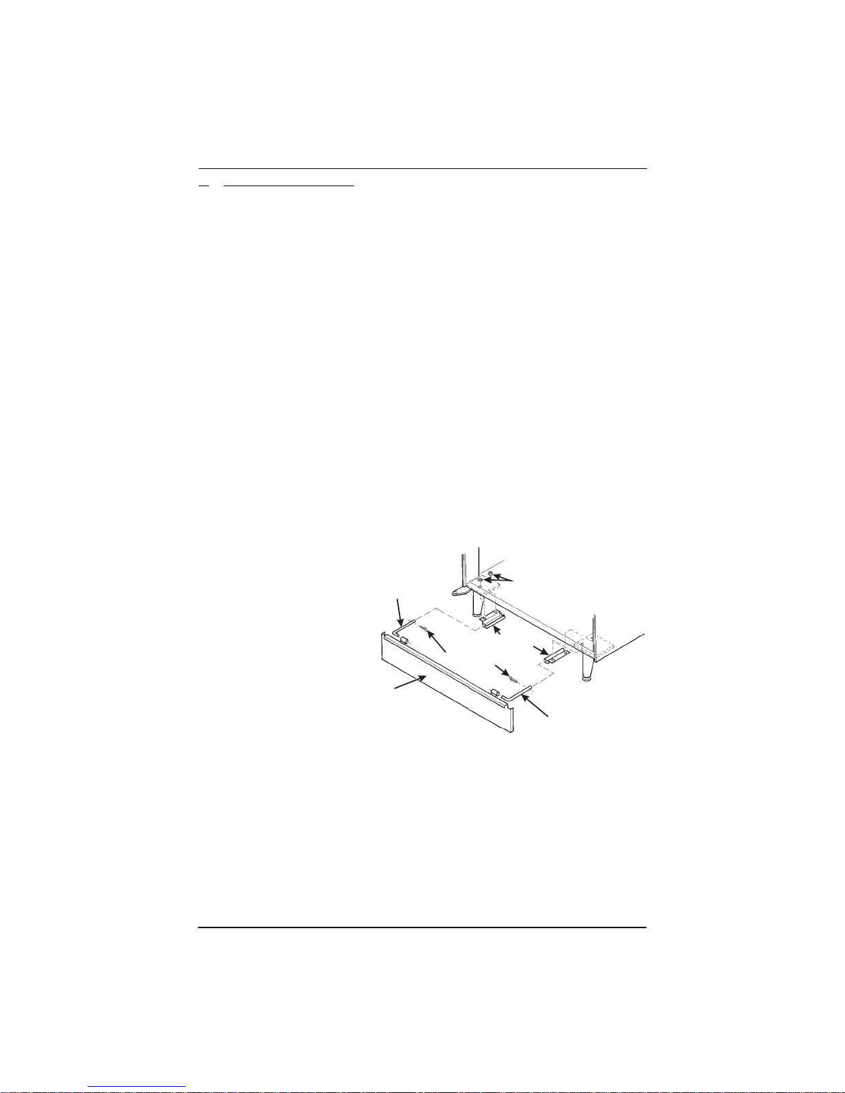
2. Mount the Base Plate:
WARNING
DO NOT MOVE THE CABINET WHILE HEX HEAD
SCREWS AND/OR CARRIAGE BOLT S ARE LOOSENED. THE CABINET WOULD BECOME UNSTABLE
AND LIKELY TO TIP AND CAUSE INJURY.
a. Remove the pail(s) from the inside of the merchandiser.
b. Re m ove the floor liner from the inside of th e merch andiser .
c. Remove the two caps as shown.
d. Loos en the le ft leg a ssemb ly carri age bol ts a nd nuts t o allo w mountin g
base plate brac ket.
e. Secure one of the base plate brackets to the leg assemb ly using the tw
carriage bolt. Tighten th e carriage b o lts and nuts.
f. Loosen the right leg assembly hex head screws to allow mounting the
other base plate bracket.
g. Secure the other base plate bracket to the right leg assembly using the
two hex head screws. Tighten the hex head screws.
h. Insert the short arms of the slides into the hinged tabs of the base plate
Position the slide so the notch near the short arm is on the bottom side
i. Insert the long
arms of the
slides in to the
base plate
brackets.
SLIDE - L.H.
j. Insert and
secure a cotter
pin through
the hol e in the
back of each
of the slides.
k. Pus h the base
plate toward
the merchandiser cabinet .
ASE PLATE
ASSEMBLY
BASE PLATE BRACKET
COTTER PIN
The front tabs of the base plate bracket s sho uld seat i n the notc hes in th
long arms of the slides.
l. Replace the caps, liner, and pail(s) removed prev ious ly.
CAPS
SLIDE - R.H.
6730013 17
February, 2003
Hot Drink Center II Set-Up Manual
3. Set Up the Menu Assembly
Glass door:
a. Swivel the cup turrets away from the door.
b. Re m ove the thumb screws as shown, and slide out the menu assembly.
c. Install selec tio n inserts as shown .
d. Re install the menu assembly in the reverse order of assembly.
18 6730013
February, 2003
Hot Drink Center II Set-Up Manual
1
C
4. I nstall the Water Filter Cartridge:
IF YOUR MERCHANDISER HAS THE WAT ER FILTER
OPTION, IT CANNOT BE OPERATED WITHOUT A
PROPERLY INSTALLED WATER FILTER CARTRIDGE. If you do not have the water fil ter option, continue
with "Fill the Tank"
UNO BRAND ...
Check the water filter installation record. There is a place to write
the vend number on the cartridge. The cartridge is effective for a
maximum of 64,000 7 oz. vends, 56,000 8 oz. vends, 50,000 9 oz.
vends, or 37,000 12 oz. vends. Local conditions may require more
.
NOTE
frequent replacem ent.
CUNO
FILTER
CUNO FILTER
HEAD ASSEMBLY
GROOVE
LOCKING
FILTER
TAB
FILTER
LOCKING
TAB
TO INSTALL
THE FILTER:
1. INSERT NEW FILTER,
ROTATE COUNTERCLOCKWISE UNTIL
FILTER LOCKING TAB
SNAPS INTO GROOVE
AS SHOWN.
. CLOSE THE WATER SHUT
-OFF VALVE BY TURNING
THE KNOB TO THE
HORIZONTAL POSITION
AS SHOWN.
SHUT-OFF
TO REMOVE FILTER:
WATER
KNOB
2. LIFT THE FILTER
LOCKING TAB,
ROTATE FILTER
CLOCKWISE AND
PULL DOWN AS
SHOWN.
6730013 19
February, 2003
Hot Drink Center II Set-Up Manual
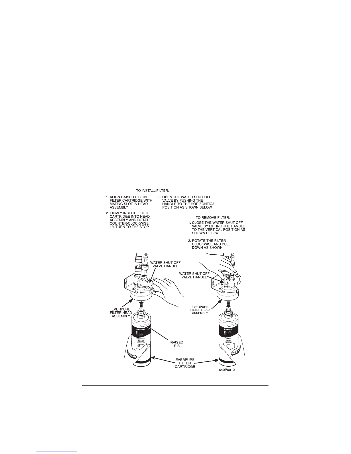
EVERPURE BRAND ...
NOTE
Check the water filter installation record. There is a place to
write the vend number on the cartridge. The cartridge is effe ctive for a maximum of 26,000 7 oz. vends, 22,000 8 oz. vends,
20,000 9 oz. vends, or 15, 000 12 oz. vends. Local conditions
may require more frequent replacemen t.
National Vendors recommends that you do the foll owing pro cedure the first time
you fill the tank in your merchandiser:
a. Remove the small inner "O" ring from the filter cartridge.
b. Install the f ilter cartridge.
c. Turn on the water a t its source, and perform the tank fil ling procedure.
d. Turn off the water at its source, remove the filter cartridge, and replace
the "O" ring.
e. Install the filter cartridge.
20 6730013
February, 2003

Hot Drink Center II Set-Up Manual
E
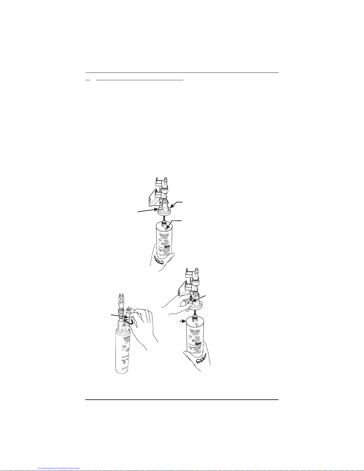
HYDROLIFE BRAND...
INSTALLATION:
1. Place the filter insi d e the canister . Be sure the o-ring is seated in the canister just below the threads.
2. S cr ew th e ca nist er and fil te r ass emb ly onto t he fi lte r he ad un t il it come s to a
stop.
3. Ope n the water valve on the inlet line by rotating the handle to the vertical
position as shown.
REMOVAL
4. Close the valve on the inlet line by rotating the handle into the horizontal
position as shown.
5. Re lieve water pressure by performing two or thre e wat er throws (see the
Programming Guide).
6. Unscrew the filter and caniste r as sembly from the filter head. Remove the
filter fro m th e canister.
OPEN
POSITION
INSTALL
HYDROLIFE
FILTER HEAD
O-RING
REMOV
OPEN
POSITION
VALVE
CLOSED
POSITION
FILTER
CANISTER
6730013 21
February, 2003

Hot Drink Center II Set-Up Manual
5. Load the Optional Filter Paper:
a. Turn the fastener 1/4 turn counterclockwise and remove the filter paper
cover.
b. Inse rt filter paper in the filte r paper housing as shown.
c. Feed the paper out of the housing as shown by the arrows molded into
the back wall of the filter paper housing.
d. Lift up the limit s witch and feed the paper past it as s hown. Release the
limit s w i tch.
e. Replace the cover.
22 6730013
February, 2003

Hot Drink Center II Set-Up Manual
f. Refer to routing label on filter paper cover. Feed paper under paper
guide shaft an d over rounded edge of stainless st ee l brackets as shown.
g. Lift and rot ate the idle r roller assembly up.
h. Route the paper under the brewer cylinder and the idler rollers.
i. Release the idler roller assem b ly, capturing the filter paper.
j. Route the paper into the ground s buc ket.
6730013 23
February, 2003

Hot Drink Center II Set-Up Manual
6. In stall the Optional Coin Box Lock
a. Ins ta ll th e lo ck cy l in d er,
washer , and nut in the order
shown.
b. Tighten the nut.
c. Install the lock bar as shown,
and secure with the screw.
LOCK
CYLINDER
7. Load the Coin Mechani s m
a. Open the cabinet door and the monetary door.
b. Insert coins into their respe ctive tubes until each tube has bee n filled.
c. Inspect the tubes for shingled coins and correct if necessary.
Fill the Tank:
8.
a. Make sure the main power switch is ON.
b. Turn on the water at its sourc e.
c. On the maintenanc e keypad, press , then press until the
LOCK BAR
WASHER
SCREW
NUT
24 6730013
display show s
TANK.FILL
.
d. Press . You should hear wa ter running into the tank, and the dis -
FILLING
play will s how
. The water will run until either the tank is full or
12 minutes go by, whichever happe ns first.
NOTE
The inlet water valve only stays open for 12 minutes at a time.
This is a safety feature to prevent water from running into a
leaky system and ma king a mess . It is possible for your ta nk to
take longer than 12 minutes to fill if your location has low
water pressure. To be on the safe side, check for leaks if the
water runs a long time. If you find none, everything is normal;
you just have low water pressure.
e. When you hear the water sto p running, repeat steps 3 and 4. Unde r nor-
mal circumstances, nothing will happen. If water starts running and the
display show s
FILLING
again, your pressure is low and it is just taking a
long time to fill the tank. Repeat this step if necessary to be sure your
water ta n k is full.
February, 2003

Hot Drink Center II Set-Up Manual
ID
9. Fill the Canisters:
a. Open the lid as shown, and carefully pour the appropriate product into
the can is ter. Repeat for al l canister s in th e machine .
FILL
CANISTER
L
6730013 25
February, 2003

Hot Drink Center II Set-Up Manual
10. Load Cups:
CAUTION
Use only cups which have been desig ned for use in a hot beverage ven d i ng machin e.
a. Support the cup mechanism in the upright position.
b. Push the latch forward to release the cup mechanism. Continue to sup-
port the cup mechanism while you lower it into th e loa d ing position.
c. Remove the turret cover.
OBSERVE PROPER HYGIENE - DO NOT TOUCH THE CUPS!
d. Ope n the bottom of the wrapper on a stack of cups.
e. Insert the wrapped cups into the turret and pull the wrapper out.
DO NOT FILL CUPS ABOVE THE LEVEL MARKED
ON THE OUTSIDE OF THE CUP TU R R ETS OR
ABOVE THE “FILL LINE” LABEL I NSIDE EACH TURRET, OR MOTOR JAMS WILL OCCUR.
USE ONLY THE SAME SIZE AND BRAND OF HOT
DRINK CUPS IN EACH TURRET; DO NOT INTERMIX!
f. Repl ace the turre t co ver after the turrets have been lo ad ed.
g. Be sure the cup mechanism is locked into the upright position.
26 6730013
February, 2003

CABINET
DOOR
CUP MECH
MOUNTING
BRACKET
Hot Drink Center II Set-Up Manual
LID
RETAINING
STRAP
LOAD CUPS
HERE
CUP TURRET
LATCH
CUPS
TOP VIEW
11. Tell the Machine About the Cup Size(s):
Make sure the cup sizes you select agree with the cups you have actually loaded
during setup.
a. Pres s the displ ay show s
X. OZ Y.
"X" is the cu rr e n tly sele ct ed
drink size for the cups in turret 2 (normally lar ge cups), "Y" is the currently
selected drink size for the cups in turrets 1A and 1B (normally regular
cups).
b. Pre ss to change the #1 cup ring siz e; press to change the #2
cup ring size.
6730013 27
February, 2003
Hot Drink Center II Set-Up Manual
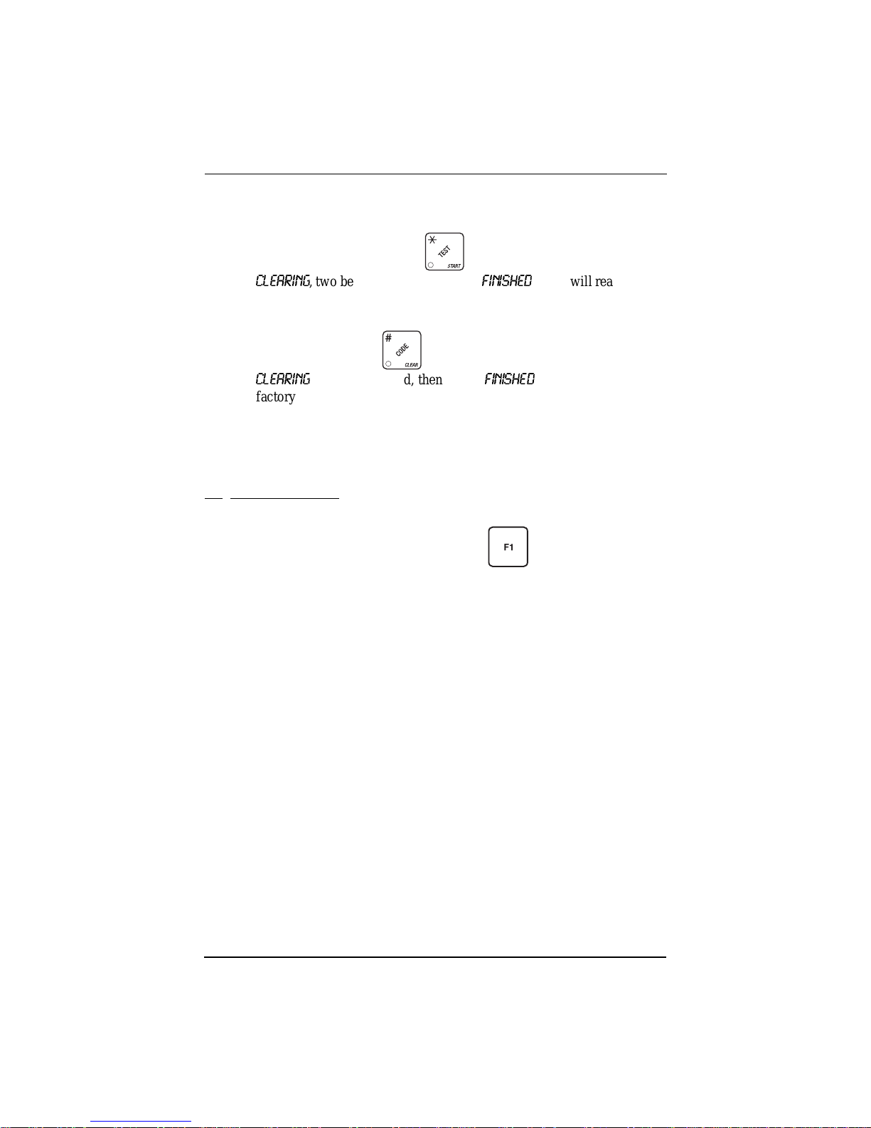
c. Any changes made to the cup si zes must be "locked in". There are two
ways to do this :
i. If you are keeping some cup sizes the same, or putting the cups in dif fe r-
ent cup rings, pr ess and hold . The display momentarily sho ws
CLEARING
, two beeps sou nd, the n shows
FINISHED
. This will reassign the
old throw times to the new cup ring, if possible.
ii. If you are loading all differe nt size cups, or want to load all new default
times, press and hold . The display momentarily shows
CLEARING
, two beeps sound, th en s hows
FINISHED
. This will reload the
factory default times for all cup sizes, clearing any custom throw times
you have established. (See t he tables on the following pages for the factory default times.)
d. CONTINUE.
12.
Test the M ach i n e :
Your Hot Drink Center is now ready to vend coffee, just as soon as the water in
the tank reaches its operating temperature. Press , and a reading of the
tank temperature is displayed. When the display shows 202° F (94° C), it is
ready for vending.
a. Close the door, make a selection, and enjoy your cup of coffee!
b. You will now need to do the followin g before your ma chine is ready to
start earning money:
•Set prices
• Set up the menu
• Establish time of day vending periods (if desired)
• Customize the drink recipes (if desired)
• Set up custom messages (if desired)
Refer to the Programming Guide for det ails on these and other procedures.
28 6730013
February, 2003

Hot Drink Center II Set-Up Manual
ADJUSTMENTS AND MINOR MAINTENANCE
This sectio n contains procedures not normall y used during setup, but may come
in han d y later on.
I. Water Valve Adjustment
W ate r valve s do not usual ly requi re adju stment , but in some cases adequa te wat er
volume cannot be achieved by the throw time setting alone (see the Program-
ming Guide). IF ABSOLUTELY NECESSARY , adjust the valves in conjunc-
tion with setting the factory default timers during the product configuration
programming mode.
a. Using a slotted screwdriver, turn the adjustment screw clockwise to
decrease the water flow rate.
b. Turn the adjustment screw counterclockwise to inc r ea se the water flow
rate.
6730013 29
February, 2003

Hot Drink Center II Set-Up Manual
II. Cup Mechanism Adj ustm en t
a. Place seven cups in the cup ring.
b. O b serve the clearance as shown in view B.
c. If necessary adjust by first loosening the adjustm ent arm screw (view
A).
d. M o ve adjustment arm until correct clearance is achieved.
e. Ho ld ad ju s t ment arm in pl a c e and ti gh t en ad ju st m e n t ar m screw.
ADJUSTMENT
ARM
VIEW A
LOOSEN SCREW
MOVE ARM
CUP
CAM
CUP
CAM
CORRECT
VIEW B
This clearance is just
large enough to allow
30 6730013
ADJUSTMENT
cup ejection
ADJUSTED
TOO TIGHT
ADJUSTED
TOO LOOSE
This side is snug
against cam
316P0118
February, 2003
Hot Drink Center II Set-Up Manual
A
si
g
b
c
f
T
t
a
g
G
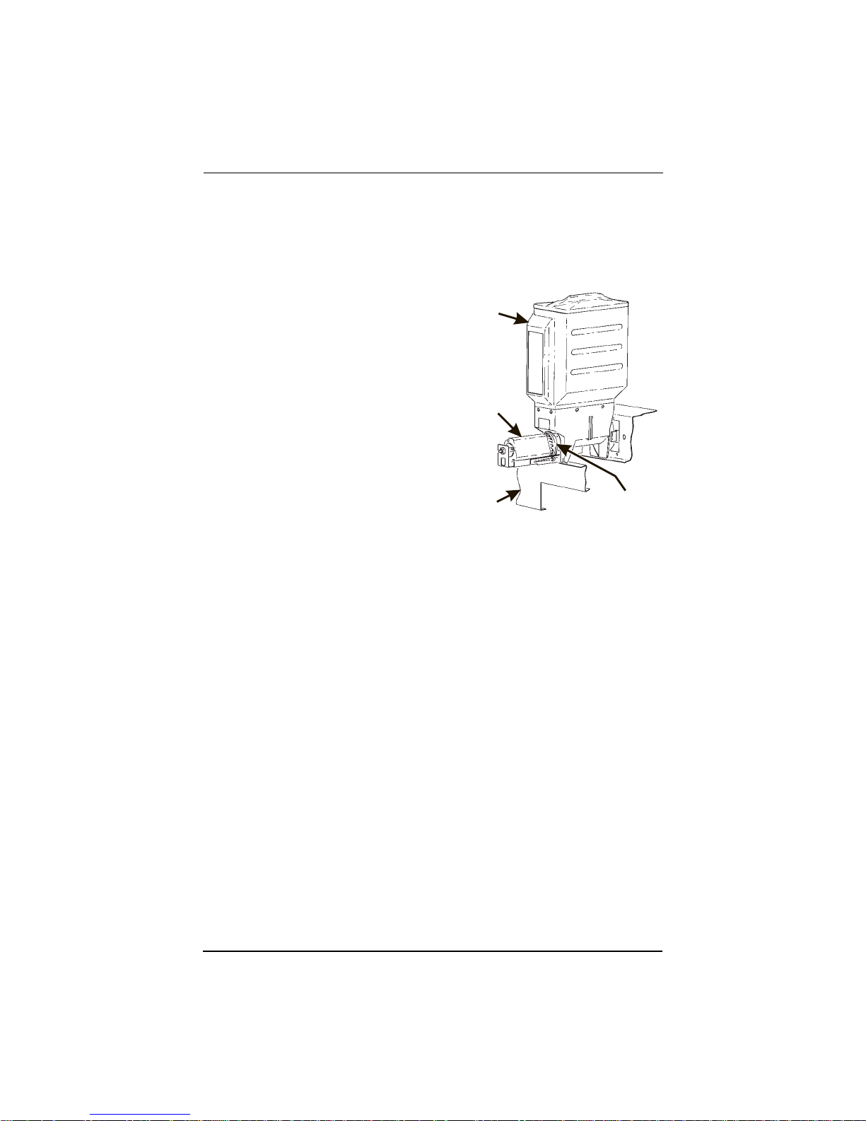
III. Grinder Adjustment
grind that is within the acceptable range will result in more controlled dispen
ng of grounds into the brew baske t, and better extracti on of coffee flavors. A
rind that is too coarse results in poor ext r action and spraying grounds in the
rewer area. A grind that is too fine can overload the grinder motor as wel l as
log the screens in the brew basket and
unnel.
he degree-of-grind scale attached to
he grinder motor represents an accept-
ble range of grinds. Do not set the
rinder beyond the limits of this scale.
a. Push the locking collar
toward the canister and turn
the grinder motor.
b. Turn clockwise for a finer
grind and counterc lockwise
for a coarser grind. A notch
on the locking collar indicates
the grind on the scale.
Do not turn the grinder motor too far in the clockwise direction. The grinder blades will come into contact an d may be
damaged.
c. Adjusting the gr ind m ay make it necessary to readjust the throw time.
Use the factory default times as a startin g p o in t and proceed according
to the dir e ct io ns in the "COLLECTING DRY PRODUCT GRAM
THROWS" section of the Programming Guide.
BEAN
CANISTER
GRINDER
MOTOR
CANISTER
SHELF
CAUTION
LOCKIN
COLLAR
6730013 31
February, 2003
Hot Drink Center II Set-Up Manual
t
BRACKET ASSEMBLY
GRINDER
T
Y
FILL
CANISTER
CANISTER
SHELF
PINS ON MOTOR
SHAFT MUST ENGAGE
SLOTS IN CANISTER
COUPLER
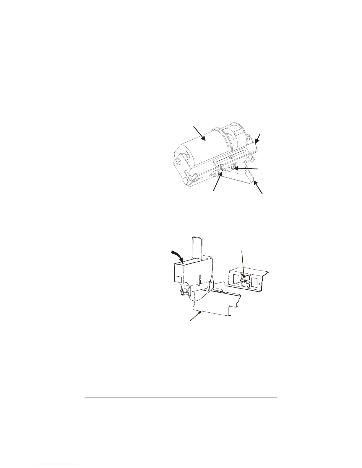
IV. Disengaging the Grinder
At certain times, the bean grinder(s) need to be disengaged from the bean canister(s).
WARNING
Keep your fingers clear of all moving parts.
a. Using a screwdriver han-
dle or other suitable tool,
GRINDER
push up on the catch
spring far enough to free
the catch spring pin from
the grinder shelf bracke t
assembly.
b. Pull the grinder and
grinder bracke t as sembly
towards you.
c. Pivot the grinder and
grinder bracke t as sembly
CATCH SPRING PIN
GRINDER SHELF
down.
d. Re -engage the grinder by pivo ting it back up into position.
V. Canister Installation
a. Place the canister
in position as
shown.
b. Engage the pins
FILL
CANISTER
PINS ON MOTOR
SHAFT MUST ENGAGE
SLOTS IN CANISTER
COUPLER
on the motor shaft
with the slots in
the can ister coupler.
c. Fit tabs on cani s-
ter into the slots
on the canister
shelf.
d. To ensur e ca ni s-
ter is correctly
CANISTER
SHELF
626P0017
engaged with the rear mounting bracket, gently push down on the fron
edge of the canister lid.
BRACKE
ASSEMBL
CATCH
SPRING
e. Canister Caps. The parts bag contains a number of red vinyl caps.
Place these caps over the canister nozzle as shown to avoid spilling
product when removing and replacing the canisters.
32 6730013
February, 2003
Hot Drink Center II Set-Up Manual
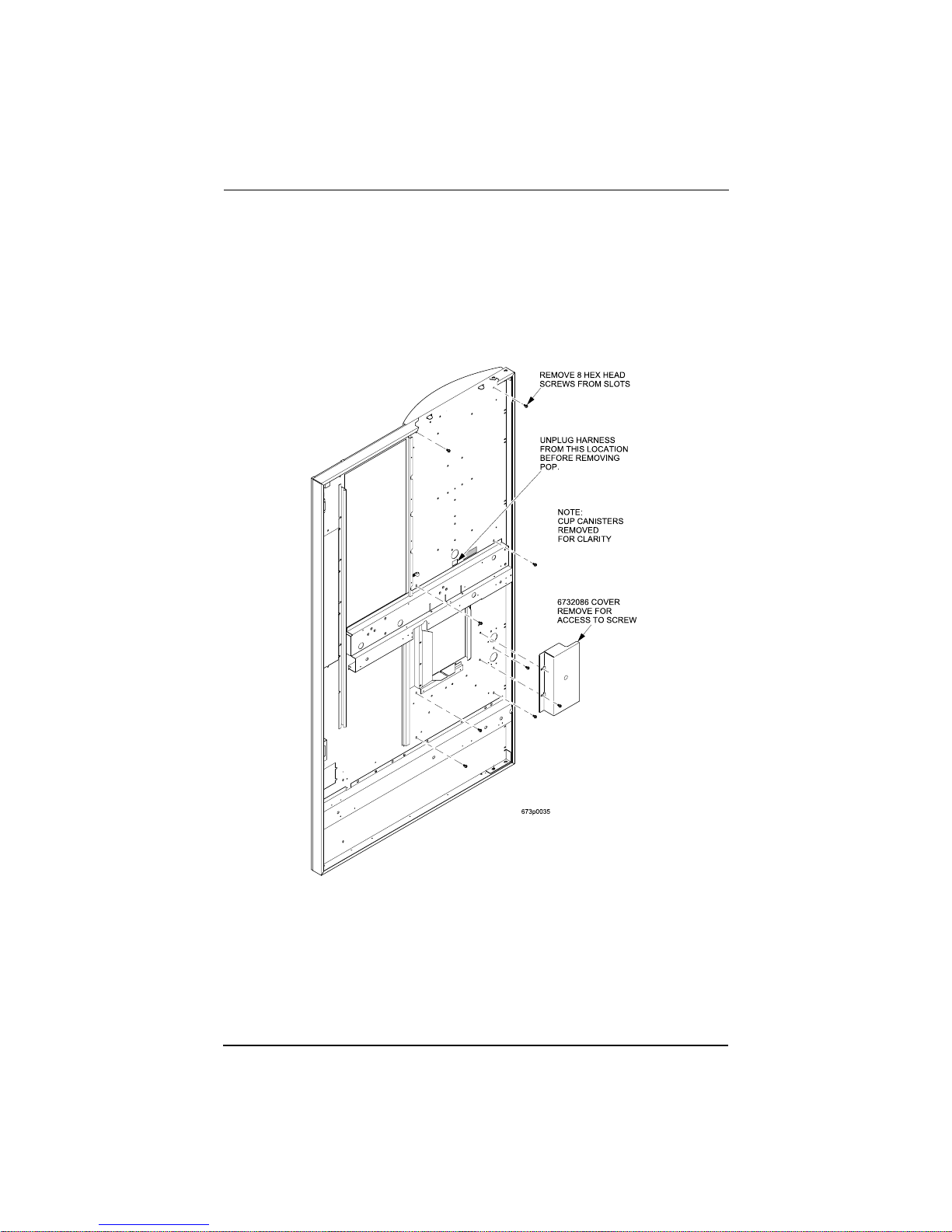
I. Removing POP to Service fluores ce n t lights , Starters an d ball asts
To remove POP to service fluorescent lights, starters and ballasts:
a. From the interior of door, unplug the harness directly below
cup/canisters as labeled on door.
b. Re move 8 hex screws that are in slots nex t to the white dots, from the
interior of door as marked in the illustration. (Remove cover to access
one of the 8 screws).
c. Release the cup canisters so they tip outwards, away from the door, to
gain access to the top two screws. The POP will then be hanging by 2
hanger brackets in sl ots on the top of the door. Remove the POP from
the FRONT of the machine by lifting from the cup station opening and
the top trim. Lift and pull straight out. This will allow access to change
bulbs, starters and ballasts. To reinstall, reverse process.
6730013 33
February, 2003

Hot Drink Center II Set-Up Manual
SANITATION
I. Basics
INTRODUCTION
Anybody who servi ces ven ding machine s must use p roper s aniti zing pro cedure s.
Health regulations require that hands be clea n wh en cu ps, commodities, and
food-contact parts are handled or serviced.
In addition, Federal and State Health Departmen ts require regular cleaning and
sanitizing proc edures for food contact parts.
The inform ation in this section will explain how to c lean and sanitize the merchandiser on a day to day basis. A clean and well maintained merchandiser will
provide a better product and greater safety for your customers.
CLEANING AND SANITIZING -- WHAT’S THE DIFFERENCE?
Clean means “fre e of visib le so il”. I n cup vending mac hi ne servic ing , cle aning is
also done to mai ntain product quality and to remove food so ils, oils, and minera l
stains that could affect product taste, aroma, and appearance.
Sanitizing means the reduction, to safe levels, of the number of disease-causing
bacteria that remain on the surface after cleaning. Therefore, cleaning and sani-
tizing are done in separate steps, as prescribe d by health regulations and good
industry practice.
When you sanitize you create a healthy and hygienic condition. This leads to
wholesome foo d , which in turn leads to satisfied custo me r s.
SANITIZING IS NO SUBSTITUTE FOR A GOOD CLEANING
HOW DO I SANITIZE?
You can sanitize by using either of these two methods:
Chemicals: The object to be sanitized is treated with a bacte r icidal compound.
Heat: Raise the te mp erature of the object high enough to kill bacteria.
Water must be at least 170° F.
Hot brew water (if available) is an acceptable sanitizer. When food contact
surfaces are washed and/or rinsed, use the hot water available in the
machine.
Turn the mac hine off before using water on the machine.
34 6730013
February, 2003

Hot Drink Center II Set-Up Manual
In either case , the ob ject must be tho rough ly clean a nd compl etel y rinse d in order
for the sanitizi ng process to work. Caked-on soils not removed by clea ning, for
example, may shield bacteria from a sanitizing solution.
A GOOD PLACE TO START -- YOUR SANITATION KIT
You need to be sure that e ach machine is clean, safe, and functioning when you
leave it. In order to properly do this, yo u need to have a complete set of the right
tools. In addition to the screwdrivers, plie rs , and test equipment necessa r y to
repair a machine, you need to have the tools to clean the machine.
Here is a checklist of the items ne eded for a good sanitation kit:
Sanitation pail
Tube and nozzle brushes for food contact surfaces
Utility brush for dry spillage around canisters, etc.
Disposable towels, wet-strength and lint-free
NOTE
Wipi ng with towels can recontaminate sa nitized food-contact
parts. Ther efor e, towe ls s hould n ot b e use d to dry food-c ont act
surfaces. Instead, these parts should be air dried.
Spray detergent, diluted to desired s trength
Urn cleaner packets for coffee stains and oils
Odor control chemicals for pails
Replacement parts (if the exchange method is used)
Cabinet polish or window cleaner for the outsid e of the machine
Feel free to add some items to this list. For example, you may want to use a portable vacuum clea ner.
6730013 35
February, 2003

Hot Drink Center II Set-Up Manual
II. Clean the Hot Water Tank
Some smell and/or taste problems may occur in new machines. Follow this procedure to clean the hot water tank if you experience problems:
1. If the machine is in service, remove power from the machine.
2. Dissolve 1 tablespoon of common baking soda in a cup of water .
WARNING
The water tank may be HOT. Be careful when working on the
tank.
3. Loosen or remove the hot water tank li d and pour the baking soda solution
into the ta nk.
4. Apply power to the machine.
5. If the tank is not full, fill it.
6. Allow the tank to reach its operating temperature.
7. Leave the solution in the tank for AT LEAST
solution in the tank for 1 hour.
8. Dra in the tank.
9. Re fill the tank, then drain again.
10. Refill th e tank and put the machine back int o se rvice.
III. Sanitation Procedures
Refer to the re commended cl eanin g and san itati on in te rval ta ble on the final pa ge
of this section. For each item, complete the procedure as outlined here.
½ hour. If possib le, le ave the
Food-Contact Parts
NOTE
All food-contac t parts must be cleaned and saniti zed. Air dry,
do not wipe dry.
Ingredient Canis t ers
- Empty and wash the canisters, augers, and spouts.
Sanitiz e with hot water and allow to air dr y completely before returning to
cabinet.
Mixing Bowls
- The inside of all mi xing bowls can b e rins ed by perf orming
the “Bowl Rinse” operation as outlined in the Programming section of this
manual.
If needed, remove mixing bowls from the dry ingredient shelf. Wash the
mixing bowl lids and sanitize with hot water. Allow to completely ai r dry
before reassembling.
Whipper Lids and Impellers
- Remove lids and impellers from the whipper housings, wash the lids and impeller housing. Sanitize with hot water
and allow to air dry before reassembling.
36 6730013
February, 2003

Hot Drink Center II Set-Up Manual
Beverage Discharge Nozzles - Disconnect the beverage dispensing tube
from the noz zles. Remove the no zzle s from the m ounting bracke t. Remov e
the cap from the nozzle, wash cl ean and sani tize the nozzles and cap. Refer
to the tubing connection diagram for proper routing.
Brewer and Brewer Funnel
performing the BREW RINSE operation as outlined in the programmi ng
sectio n . The m ac hi n e f ea tu r es an au to m a t ic brewer sanit i zing featu r e al so
described in the programming section.
At times, it may be necessary to wash and sanitize the individual brewer
parts. If so, disconnect the tubes from the brewer funnel. Remove the
brewer barrel from its su pport. Remove the brewer funnel assemblies.
Thoroughly wash all parts using soap and water. Sanitize by rinsing thoroughly with hot water.
Coffee Chutes
- Remove the metal chute(s), wash clean, and sanitize by
rinsing with hot water. Air dry before reinstalling.
Condiment Chute Assembly
from the condiment canisters. Thoroughly wash all parts using soap and
water. Sanitize by rinsing thoroughly with hot water.Non Food-Contact
Parts
Non Food-Contact Parts
Cup Delivery Compartment
chandiser. Wash clean and rins e with hot water.
Exhaust Fan Filter
- Remove the filter from its hou si ng. Wash wit h soap
and water , rinse, wring dry, and replace into housin g.
Waste Pai l
- Empty, wash, and rinse with hot water. Sprinkle detergent
powder in the bottom of the pail to help control odors.
Ingredient Rinse Tray
hot water. Allow to air dry.
- The tubing and brewer may be sanitized by
- Remove the condiment c hute and cover
- Remove the compartment from the mer-
- Remove product cani st ers . Wash a nd r ins e with
6730013 37
February, 2003

Hot Drink Center II Set-Up Manual
IV. Brewer Cleaning
The brewer has two main parts you can remove: the brew barrel and the funnel
screen and seal assembly. You can remove them with the brewer in the machine,
or the entire brewe r can be removed as one unit.
1. On the left side of the brewer, cut off and discard the fi lter paper (not
required for paperless).
2. Gra sp the top of the brew barrel, and turn it counter-cloc kwis e ¼ turn to the
right as shown. Lift straight up and remove.
3. Re move the hose from the bottom of the funnel screen and seal assembly.
4. At this poi nt , y ou ca n remove th e brewer or leave it in th e machine .
5. To remove the brewer, tilt the latch down and swivel the brewer up and out.
38 6730013
February, 2003

Hot Drink Center II Set-Up Manual
6. Re move the screen and seal assembly as shown:
a. Press down on the tabs with your fingers, and slide straight back.
b. Lift straight up and pull out.
Brewer Assembly w/ Paper
Paperless Brewer Asse m bly
6730013 39
February, 2003

Hot Drink Center II Set-Up Manual
7. Thoroughly wash all parts using soap and water. Sanitize by rinsing thoroughly with hot water. Air dry, or blow dry with compressed air (if ava ilable).
8. If you removed the brewer, make sure the motor drive link is aligned as
shown.
a. If the motor drive link is a ligned pro perl y, the flat on the cam wheel will
seat on the bearing.
b. If the motor drive link is not aligned properly, the flat on the cam wheel
is turned away from the bearing. You must manually turn the cam
wheel to capture the bearing on the flat.
9. Ass em ble in the reverse or der of disassembly. NOTE: when repla cing the
screen and seal assembly, make sure you hear TWO CLICKS as you push it
all the way in.
10. Feed new filter paper through paper guide and brewer as shown , and don' t
forget to connect the hose(s)!
40 6730013
February, 2003

Hot Drink Center II Set-Up Manual
11. Position the Squeegee Assembly as shown in the figure below .
6730013 41
February, 2003
Paperless Brewer Assembly

Hot Drink Center II Set-Up Manual
12. Load the Optional F ilter Paper:
a. Turn the fastener
cover.
b. Inse rt filter paper in the filte r paper housing as shown.
c. Feed the paper out of the housing as shown by the arrows molded into
the back wall of the filter paper housing.
1
/4 turn counterclockwise and remove the filter paper
d. Lift up the limit s witch and feed the paper past it as s hown. Release the
limit s w i tch.
e. Replace the cover.
42 6730013
February, 2003

Hot Drink Center II Set-Up Manual
f. Refer to routing label on filter paper cover. Feed paper under paper
guide shaft an d over rounded edge of stainless st ee l brackets as shown.
g. Lift and rot ate the idle r roller assembly up.
h. Route the paper under the brewer cylinder and the idler rollers.
i. Release the idler roller assem b ly, capturing the filter paper.
j. Route the paper into the ground s buc ket.
6730013 43
February, 2003

Hot Drink Center II Set-Up Manual
V. Overall Cleaning
Inspect your merchandiser both inside and out. Be sure to check corners and all
less visible parts of the merchandiser.
Clean wh ere needed.
Allow the inside of the cabinet to dry thoroughly befor e you close the door.
National Vendors recommends using the following supplies:
• A commercial glass cleaner on the glass in the ca binet door .
• A mild detergent and warm water on the cabinet, brewer, and other NON
ELECTRICAL comp onents.
WARNING
The plastic parts in your merchandiser should be cleaned with
mild detergent and warm water. The use of other cleaning
agents may damage the material, and should be avoided.
VI. Preventive Maintenance Cleaning
Periodically, you should visually inspect your merchandiser's hot wat er tank for
excessive lim e and scale buildup. This buildup on the tank walls, water valve s,
and heater element will vary dramatically, depending upon water quality. You
should devel op a cl ea ning and de-limeing schedule bas ed on the apparent local
water quality.
NOTE
To aid in removing scale from your merchandiser, National
Vendors has a service kit available: part number 6400080. In
addition, if your machine has the Everpure water inlet filter
system optio n, a sec ond kit (part number 6400086) is also
available.
44 6730013
February, 2003

Hot Drink Center II Set-Up Manual
6730013 45
February, 2003
TUBE ROUTING DIAGRAM
Hot Drink Center II Set-Up Manual
SEMI-
ANNUALLY
CS
CS
CS
Recommended Cleaning And Sanitation Intervals
ITEM DAILY WEEKLY MONTHLY QUARTERLY
Ingredient Canisters CS
Mixing Bowls CS
Whipper Funnels and
Impellers
Beverage Discharge Nozzles CS
Brewer, Brewer Barrel and
Brewer Funnel
Bean Grinder & Coffee
Chutes
Bean Grinder Housing S
Brewer Mechanism C
Cup Delivery Compartment C
Exhaust Fan Filter C
Grounds Pail C
Waste Pail C
S = Sanitize at this interval C = Clean only at this interval
46 6730013
February, 2003
Hot Drink Center II Set-Up Manual
Make copies of this cleaning record, cut it out , and keep it in the plastic bag
mounted on the insi de of the door. It will be your record of cleaning your Hot
Drink Center.
Record of Cleaning
20_____
JAN
FEB
MAR
APR
MAY
JUN
JUL
AUG
SEP
OCT
NOV
DEC
6730013 47
February, 2003
 Loading...