

Page 1
FORM
: D4807
Weatherproof
Thermostat
Instructions
DESCRIPTION
SureSTAT thermostats are designed to control automatic ventilation and heating systems. The wide 30° t o 110°F temperature
range allows them to be used in many applications. The switches are enclosed and protected from the environment. The sensor is
made of stainless steel and is firmly attached to the exterior of the case.
SPECIFICATIONS
Model T110 – Single stage (One SPDT switch) hard wired thermostat.
Model T120 – Two stage (Two SPDT switches) hard wired thermostat.
Model T118P – Single stage (One SPDT switch) thermostat prewired with an 8’ Plug-in cord.
Model T1120P – Single stage (One SPDT switch) thermostat prewired with a 20’ Plug-in cord.
Model T130P – Single stage (One SPDT switch) thermostat prewired with an 8’ Plug-in cord and
extended sensor.
Temperature Range: 30° to 110°F (Maximum operating temperature rang e 0° to 140°F)
Differential: Approx. 3 1/2°F (Model T120 has a fixed 3°F diff erential between stages)
Electrical Rating: Millivolt to 120 VAC
Maximum Elec. Load: 16 amps at 120 VAC
GENERAL SAFETY INFORMATION
1. Make certain that the electrical ratings of the thermostat conform to the power source and to the load(s) being controlled. Loads
exceeding the rating of the thermostat should be handled with a suitably rated relay or motor starter.
2. Disconnect all power before installing or servicing control. If the power disconnect is out of sight, lock it in the open position and tag it to
prevent unexpected application of power. Failure to do so could result in fatal electric shock.
3. Special attention must be given to any grounding information pertaining to this thermostat and to any other equipment associated with
its installation and use. To ensure a proper ground, that grounding means must be checked by a qualified electrician.
4. This thermostat is intended ONLY for installation in accordance with the United States National Electrical Code (NEC), all applicable
local codes and ordinances, and all sections of this manual. All wiring should be done by a qualified electrician, using copper wire only.
5. This thermostat is intended for general heating or cooling ONLY. It must NOT be used in potentially dangerous locations such as
flammable, explosive or chemical-laden atmospheres.
6. These thermostats are designed for use only as operating controls. Where an operating control failure would result in personal injury
and/or loss of property, it is the responsibility of the installer to add backup devices (safety, limit controls) or systems (alarm,
supervisory systems) that protect against, or warn of, control failure.
7. Use this thermostat as an operating control only.
INSTALLATION INSTRUCTIONS
Location: Mount control 5 to 6 feet above the floor where it will be exposed to the average temperature of the controlled space.
Do not mount control where it will be affected by unusual heat or cold such as against an outside wall that is not well insulated or
directly exposed to body heat or in sunlight. Avoid locations hear a door, window, or other opening.
Mounting: Mount control to a flat surface with screws through the holes in the mounting ears on the back side of the thermostat
case. If you must mount control to an uneven surface, use ONLY the top mounting hole to prevent twisting the thermostat case.
DO NOT dent or deform sensing bulb. Doing so can change the calibration of the control.
General Wiring: (For T110 & T120 models only)
1. Remove the four screws securing the cover to the thermostat, and take the cover off.
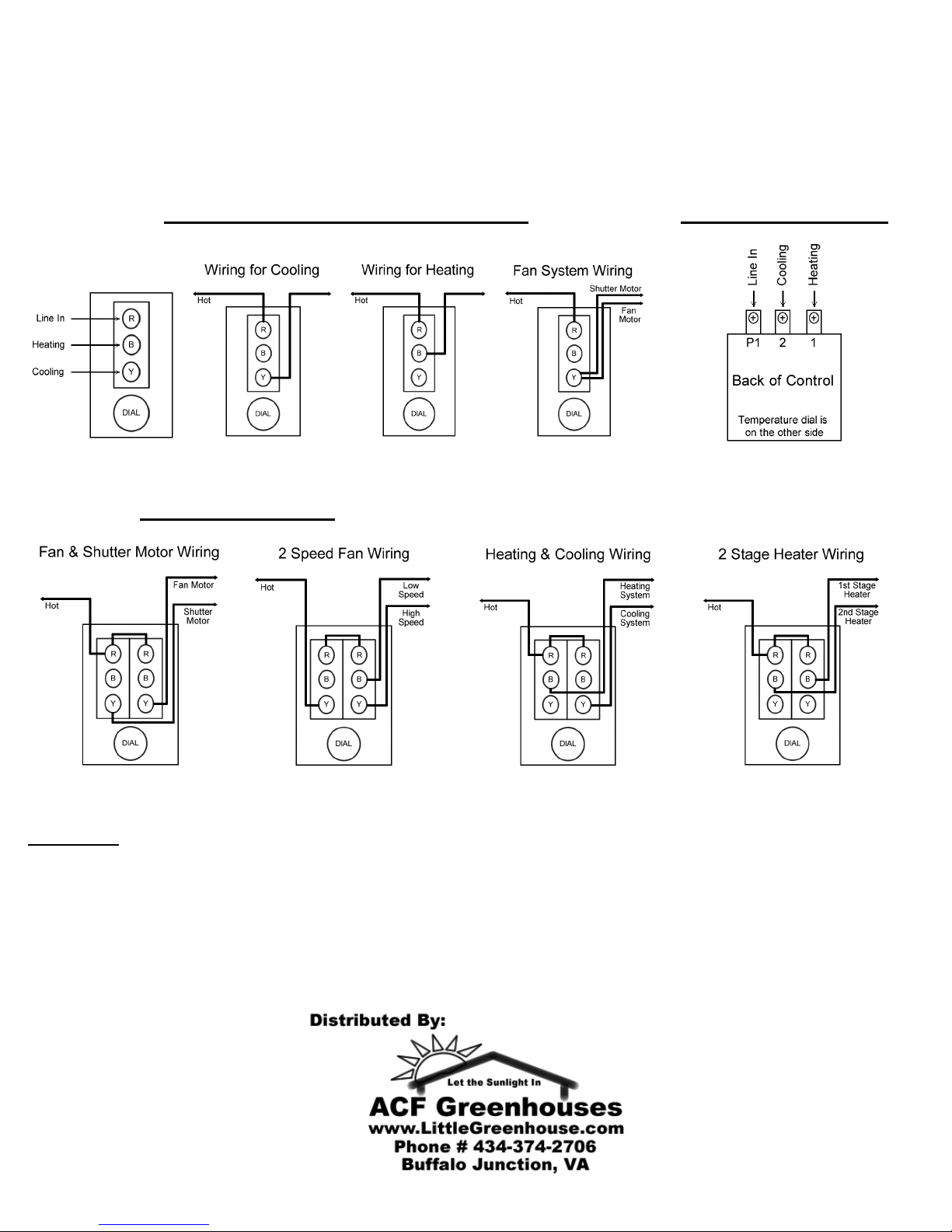
2. Connect wires to the appropriate terminals (heating or cooling). See wiring diagrams on next page.
3. Place cover back on thermostat for safety.
4. Connect power supply.
5. Tighten screws on thermostat cover.
6. Turn the dial so that the desired temperature is in front of the pointer.
Checking Wiring:
• Turn dial to 110°F. (heating mode) device should come on. (cooling mode) device should be off.
• Turn dial to 30° F. (heating mode) device should cut off. (cooling mode) device should come on.
• As the dial passes current room temperature, you should hear a faint click from the thermostat.
ACF Greenhouses
Page 2
Switching Between Heating & Cooling: (For all models)
1. Disconnect the power supply.
2. Remove the four screws securing the cover to the thermostat, and take the cover off.
3. Switching to cooling mode: Remove the wire connected to the heating terminal & connect it to the cooling terminal.
Switching to heating mode: Remove the wire connected to the cooling terminal & connect it to the heating terminal.
Wiring for Models T110, T118P, & T1120P Wiring for Model T130P
T110 Only
Wiring for Model T120
WARRANTY
SureSTAT thermostats are warranted by the manufacturer to the original user against defects in workmanship or materials under
use for one year after the date of purchase. Any part which is determined to be defective in material or workmanship and returned
to the supplier, shipping costs prepaid, will be repaired or replaced at the supplier’s option.
This warranty is expressly in lieu of all other warranties, either expressed or implied. Any implied warranty of merchantability or
fitness for a particular purpose is hereby excluded. In no event or circumstance shall the supplier be responsible for any incidental
or consequential damages whatsoever.
ACF Greenhouses
 Loading...