

Page 1
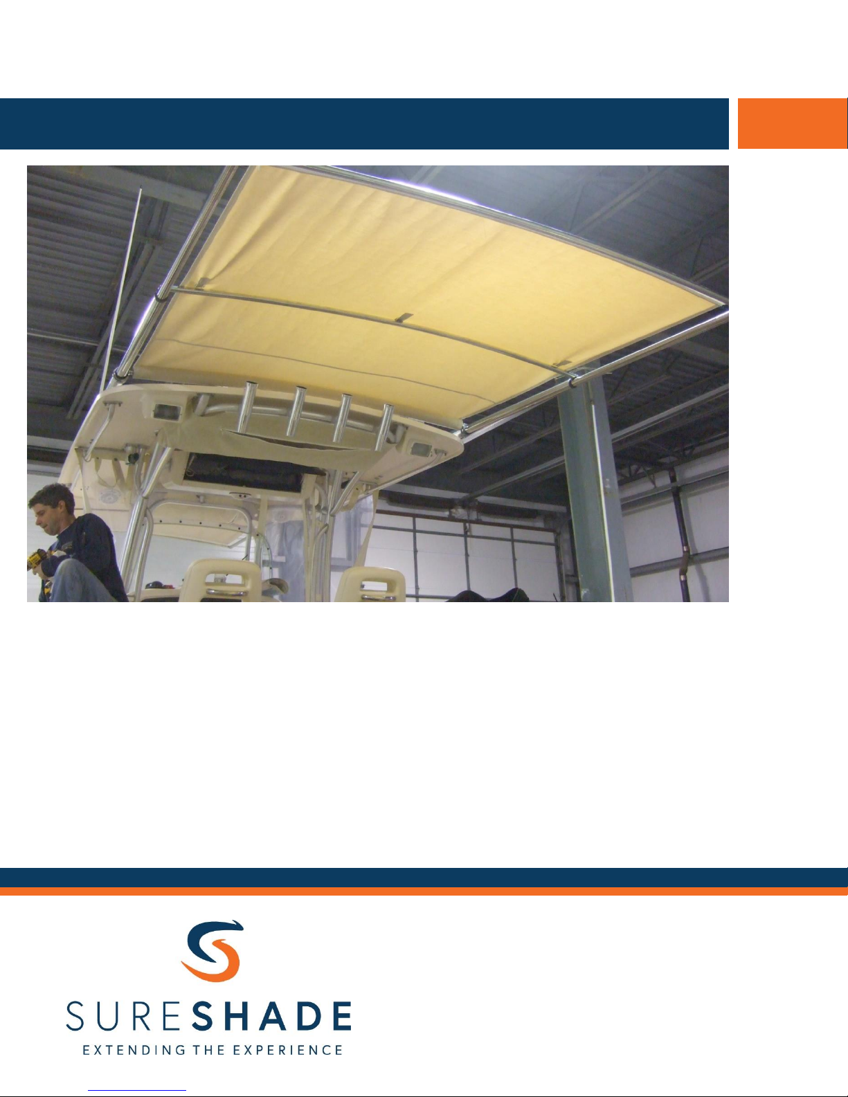
Automated Shade Installation
SURESHADE
PO Box 51294
Philadelphia, PA 19115
Tel: 1-877-333-8323
International: 215-673-2307
www.sureshade.com
The SureShade® ATF automated shade system is an electric
power-driven retractable shade featuring a self-supported
stainless steel framework.
This installation guide includes instructions for properly installing
the framework and electrical components for our automated
shade systems.
Page 1 of 5
S U R E S H A D E T E C H N I C A L D O C U M E N T A T I O N
Page 2
SureShade ATF Automated Shade Installation
1) Mark the position of the mounting clamps (Figs 1 – 4)
2) Secure the mounting clamps in place
3) Secure the actuators in place
4) Secure the roller assembly in place
5) Secure the crossbars in place (Fig 5 – 6)
6) Set up the electrical system (Fig 7)
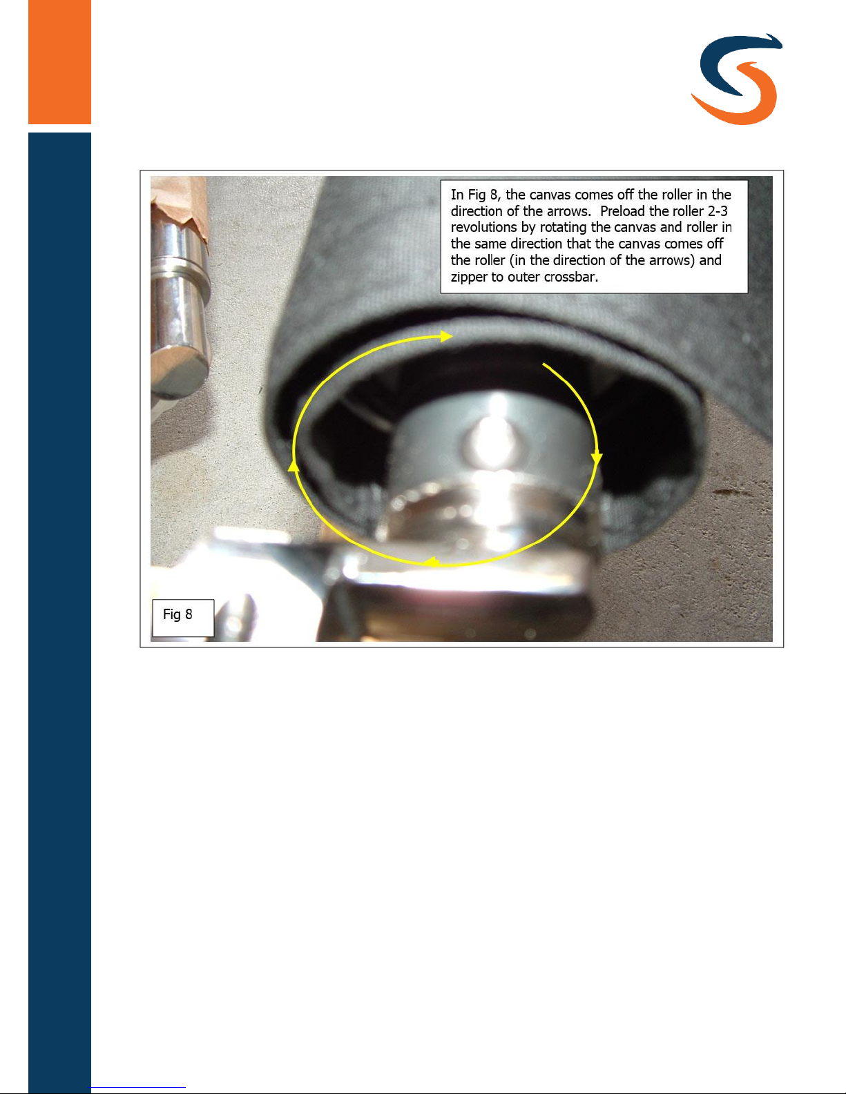
7) Preload the canvas (Fig 8)
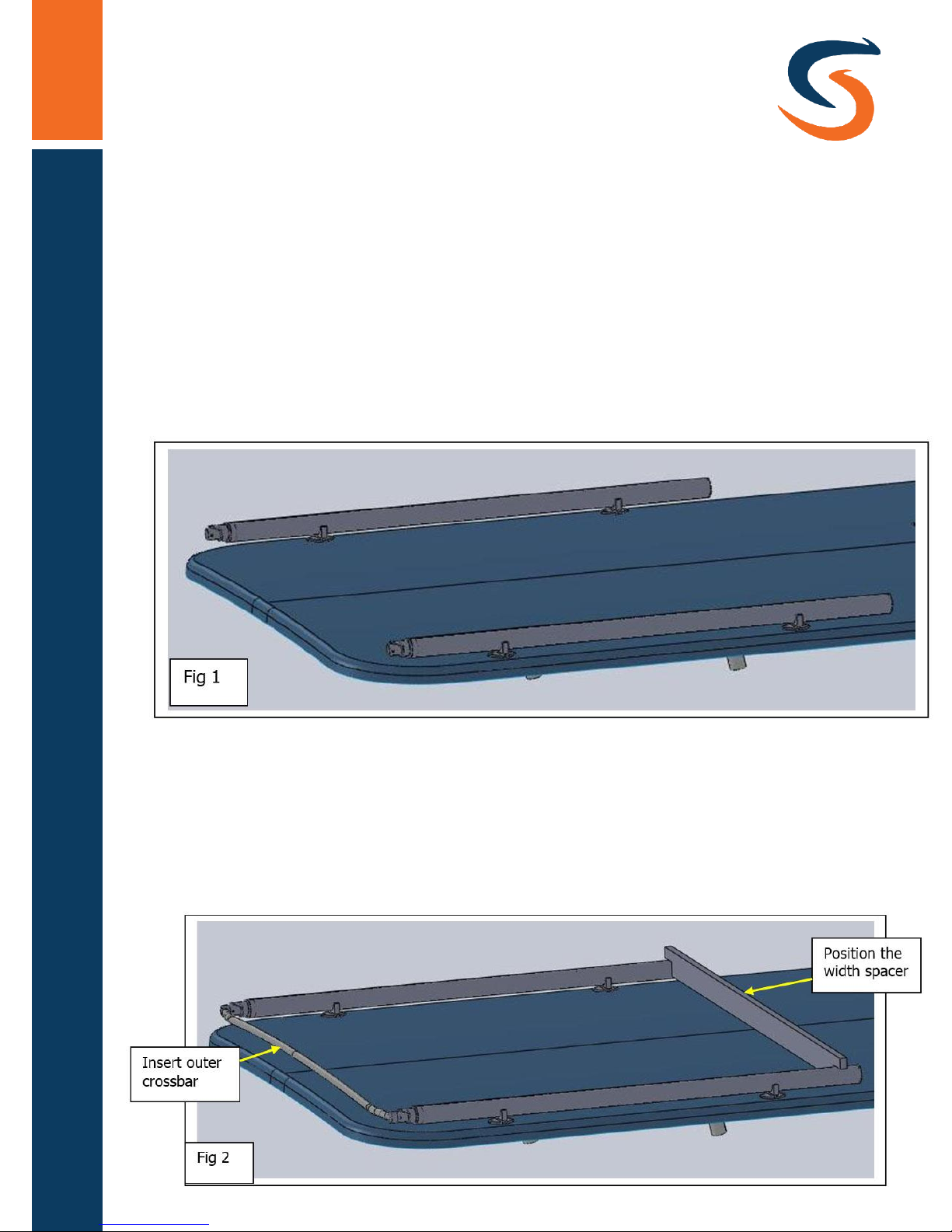
Position both actuators on top of the hardtop resting on the bottom
half of the mounting clamps (Fig 1).
Insert the outer crossbar onto the actuators and position the width
spacer on the other end of the actuators to align the actuators to be
parallel (Fig 2).
NOTE – the actuators must be aligned (parallel) to ensure proper
functioning of the shade system.
Page 2 of 5
Page 3
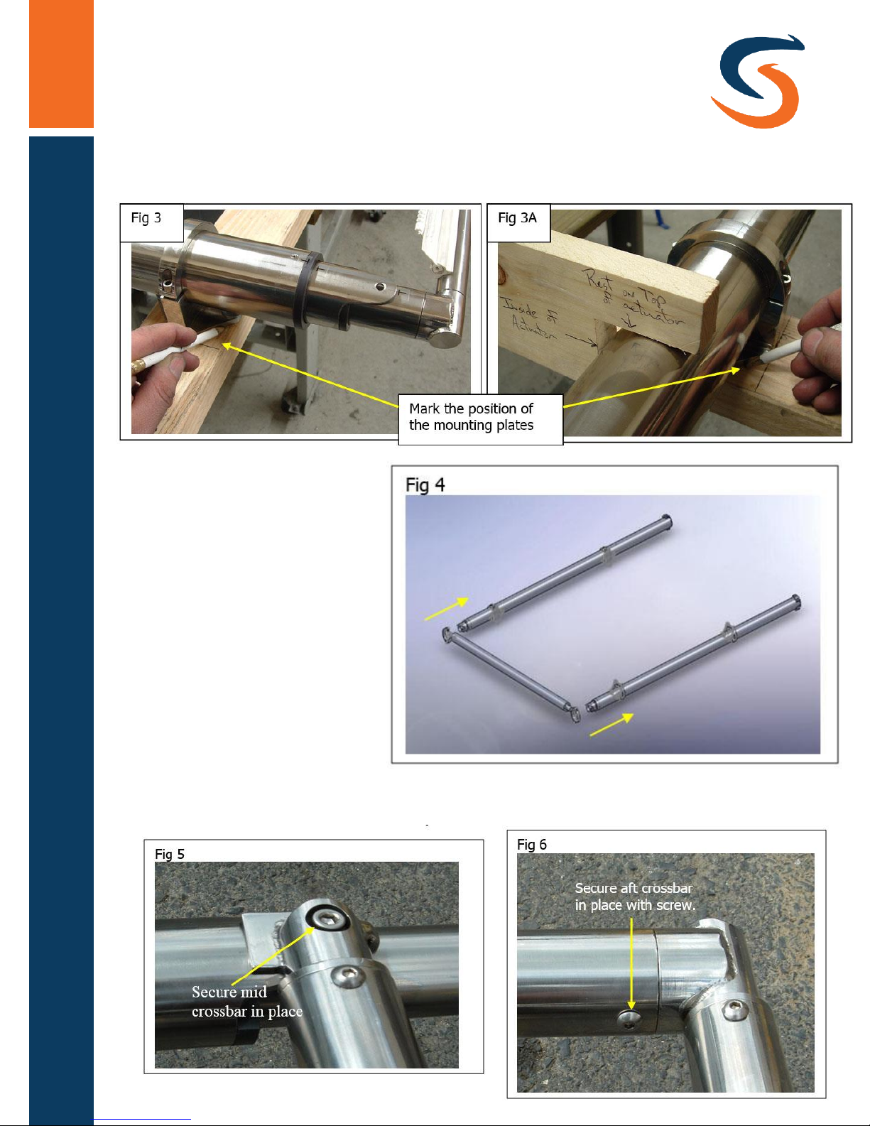
Mark the position of the mounting plates on the hardtop
(Fig 3 & 3A).
Remove the crossbar,
spacer and actuators
from the mounting
plate so you can drill
and secure the
mounting clamp to the
hardtop in the marked
locations. Secure
actuators to the
mounting clamps and
slide the roller assembly
onto actuators and
secure in place (Fig 4).
Slide crossbars onto actuators and secure in place.
Page 3 of 5
SureShade ATF Automated Shade Installation
Page 4
The electrical housing is pre-wired and tested before shipping.
The wires that provide power to the controller contain a 5 amp fuse
that protects the circuit board and a 15 amp fuse that protects the
motors from overload.
The electrical housing controls the retracted and extended positions as
well as the synchronization of the actuators’ movement. The
synchronization is accomplished by sensors positioned inside the
actuator that communicate with the electrical housing. These sensors,
along with the housing software, will keep the two actuators
synchronized within ½” of each other during travel. When an actuator
gets ½” ahead of the other actuator the system will shut the faster
actuator down for a split second until the slower actuator catches up
and then continues movement again.
Page 4 of 5
SureShade ATF Automated Shade Installation
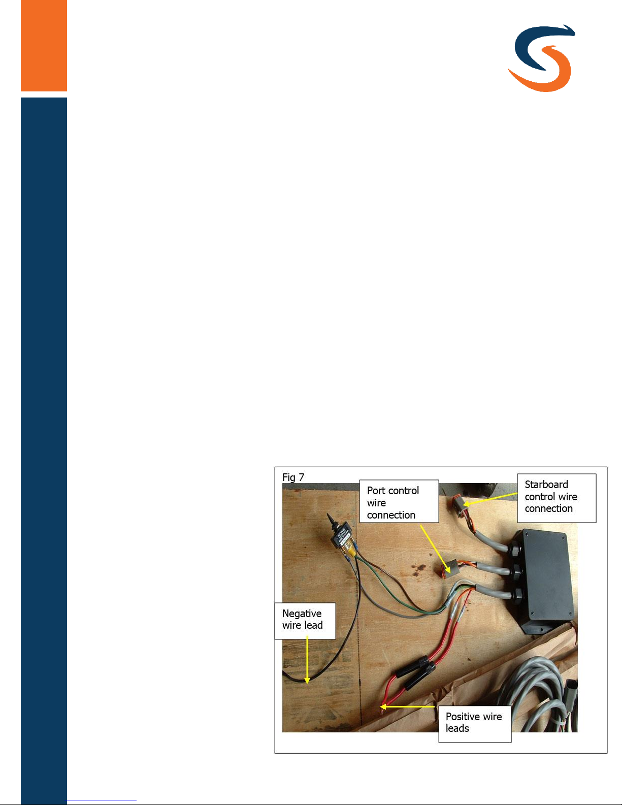
1) All control wires for the actuators to the controller are supplied with Deutsch
connectors. Once the control wiring is properly fed through tubing and
fiberglass, connect one end of the control wire to the actuator and the other
end to the electrical housing.
2) Connect the positive and negative wires to a power source as shown in Fig 7.
If running power from
a power source to the
controller, be sure that
the wires providing power
to the controller are an
8 gauge wire. Too small
of a gauge wire can drop
voltage and cause an
intermittent situation
during travel.
Page 5
Page 5 of 5
SureShade ATF Automated Shade Installation
© 2018 Rodan Enterprises LLC t/a SureShade
 Loading...