

Page 1

USER
USER
USER
USER MANUAL
MANUAL
MANUAL
MANUAL
T90
T90
T90
T90
THERMAL
THERMAL
THERMAL
THERMAL PRINTER
PRINTER
PRINTER
PRINTER
The contents of this document are subject to change without notice
Page 2

CAUTIONS
�
It’s grade
A
product
,
maybe it cause wireless jammer in the environment. I n
such circumstances, need the user to do related step s .
�
Without permission, do not change the content of this document .
�
No part of this document may be reproduced, transmitted in any form or by
any means, without the prior written permission .
COPYRIGHT
�
Copied date: 2010
�
Version
:
1.0
Page 3

- -
1
TABLE
TABLE
TABLE
TABLE OF
OF
OF
OF CONTENTS
CONTENTS
CONTENTS
CONTENTS
1 GENERAL DESCRIPTION . . . . . . . . . . . . . . . . . . . . . . . . . . . . . . . . . . . . . . . . . . . . . . . . . . . . . . . . . . . . . . . . . . . . . . . . . . . . . . . . . . . . . . . . . . . . . . . . . . . . . 1
1.1 Basic Specifications . . . . . . . . . . . . . . . . . . . . . . . . . . . . . . . . . . . . . . . . . . . . . . . . . . . . . . . . . . . . . . . . . . . . . . . . . . . . . . . . . . . . . . . . . . . . . . . . . . . . . . . . . . . . . . 1
1.2 Character Specifications . . . . . . . . . . . . . . . . . . . . . . . . . . . . . . . . . . . . . . . . . . . . . . . . . . . . . . . . . . . . . . . . . . . . . . . . . . . . . . . . . . . . . . . . . . . . . . . . . . . . . . . 1
1.3 Autocutter . . . . . . . . . . . . . . . . . . . . . . . . . . . . . . . . . . . . . . . . . . . . . . . . . . . . . . . . . . . . . . . . . . . . . . . . . . . . . . . . . . . . . . . . . . . . . . . . . . . . . . . . . . . . . . . . . . . . . . . . . . . . . . 1
1.4 Paper Specifications . . . . . . . . . . . . . . . . . . . . . . . . . . . . . . . . . . . . . . . . . . . . . . . . . . . . . . . . . . . . . . . . . . . . . . . . . . . . . . . . . . . . . . . . . . . . . . . . . . . . . . . . . . . . . . 1
1.5 Printable Area . . . . . . . . . . . . . . . . . . . . . . . . . . . . . . . . . . . . . . . . . . . . . . . . . . . . . . . . . . . . . . . . . . . . . . . . . . . . . . . . . . . . . . . . . . . . . . . . . . . . . . . . . . . . . . . . . . . . . . . . 1
1.6 Internal Buffer . . . . . . . . . . . . . . . . . . . . . . . . . . . . . . . . . . . . . . . . . . . . . . . . . . . . . . . . . . . . . . . . . . . . . . . . . . . . . . . . . . . . . . . . . . . . . . . . . . . . . . . . . . . . . . . . . . . . . . . 2
1.7 Printing Position and
Tear
off Position . . . . . . . . . . . . . . . . . . . . . . . . . . . . . . . . . . . . . . . . . . . . . . . . . . . . . . . . . . . . . . . . . . . . . . . . . . . . . . . . . 2
1.8 Operated Specifications . . . . . . . . . . . . . . . . . . . . . . . . . . . . . . . . . . . . . . . . . . . . . . . . . . . . . . . . . . . . . . . . . . . . . . . . . . . . . . . . . . . . . . . . . . . . . . . . . . . . . . . . 2
1.9 Reliability . . . . . . . . . . . . . . . . . . . . . . . . . . . . . . . . . . . . . . . . . . . . . . . . . . . . . . . . . . . . . . . . . . . . . . . . . . . . . . . . . . . . . . . . . . . . . . . . . . . . . . . . . . . . . . . . . . . . . . . . . . . . . . 2
1.10 Environmental Specifications . . . . . . . . . . . . . . . . . . . . . . . . . . . . . . . . . . . . . . . . . . . . . . . . . . . . . . . . . . . . . . . . . . . . . . . . . . . . . . . . . . . . . . . . . . . . . 3
2 CONFIGURATION AND INSTALLATION . . . . . . . . . . . . . . . . . . . . . . . . . . . . . . . . . . . . . . . . . . . . . . . . . . . . . . . . . . . . . . . . . . . . . . . . . . . . . 4
2.1 Interface Specifications . . . . . . . . . . . . . . . . . . . . . . . . . . . . . . . . . . . . . . . . . . . . . . . . . . . . . . . . . . . . . . . . . . . . . . . . . . . . . . . . . . . . . . . . . . . . . . . . . . . . . . . . . 4
2.1.1 RS232 Serial Interface . . . . . . . . . . . . . . . . . . . . . . . . . . . . . . . . . . . . . . . . . . . . . . . . . . . . . . . . . . . . . . . . . . . . . . . . . . . . . . . . . . . . . . . . . . 4
2.1.1.1 Specifications . . . . . . . . . . . . . . . . . . . . . . . . . . . . . . . . . . . . . . . . . . . . . . . . . . . . . . . . . . . . . . . . . . . . . . . . . . . . . . . . . . . . . . . . . . . . . . . 4
2.1.1.2 Interface Pin Signal Definition . . . . . . . . . . . . . . . . . . . . . . . . . . . . . . . . . . . . . . . . . . . . . . . . . . . . . . . . . . . . . . . . . . 4
2.1.2 IEEE 1284 Bidirectional Parallel Interface . . . . . . . . . . . . . . . . . . . . . . . . . . . . . . . . . . . . . . . . . . . . . . . . . . . . . . . 6
2.1.2.1 Specifications . . . . . . . . . . . . . . . . . . . . . . . . . . . . . . . . . . . . . . . . . . . . . . . . . . . . . . . . . . . . . . . . . . . . . . . . . . . . . . . . . . . . . . . . . . . . . . . 6
2.1.2.2 Interface Pin Signal Defination . . . . . . . . . . . . . . . . . . . . . . . . . . . . . . . . . . . . . . . . . . . . . . . . . . . . . . . . . . . . . . . . . 7
2.1.3 Ethernet Interface . . . . . . . . . . . . . . . . . . . . . . . . . . . . . . . . . . . . . . . . . . . . . . . . . . . . . . . . . . . . . . . . . . . . . . . . . . . . . . . . . . . . . . . . . . . . . . . . . 10
2.1.3. 1Interface Specifications . . . . . . . . . . . . . . . . . . . . . . . . . . . . . . . . . . . . . . . . . . . . . . . . . . . . . . . . . . . . . . . . . . . . . . . . . . . . 10
2.1.3.2 Interface Pin Signal Definition . . . . . . . . . . . . . . . . . . . . . . . . . . . . . . . . . . . . . . . . . . . . . . . . . . . . . . . . . . . . . . . . 10
2.1.4USB Interface . . . . . . . . . . . . . . . . . . . . . . . . . . . . . . . . . . . . . . . . . . . . . . . . . . . . . . . . . . . . . . . . . . . . . . . . . . . . . . . . . . . . . . . . . . . . . . . . . . . . . . . . . 10
2.1.4.1 Interface Specifications . . . . . . . . . . . . . . . . . . . . . . . . . . . . . . . . . . . . . . . . . . . . . . . . . . . . . . . . . . . . . . . . . . . . . . . . . . . . 10
2.1.4.2 Interface Pin Signal Defination . . . . . . . . . . . . . . . . . . . . . . . . . . . . . . . . . . . . . . . . . . . . . . . . . . . . . . . . . . . . . . . 11
2.2 Printer Installation . . . . . . . . . . . . . . . . . . . . . . . . . . . . . . . . . . . . . . . . . . . . . . . . . . . . . . . . . . . . . . . . . . . . . . . . . . . . . . . . . . . . . . . . . . . . . . . . . . . . . . . . . . . . . . . 11
2.2.1 Interface Connector . . . . . . . . . . . . . . . . . . . . . . . . . . . . . . . . . . . . . . . . . . . . . . . . . . . . . . . . . . . . . . . . . . . . . . . . . . . . . . . . . . . . . . . . . . . . . . 11
2.2.2 Power Connector . . . . . . . . . . . . . . . . . . . . . . . . . . . . . . . . . . . . . . . . . . . . . . . . . . . . . . . . . . . . . . . . . . . . . . . . . . . . . . . . . . . . . . . . . . . . . . . . . . 11
2.3 Drawer Connector . . . . . . . . . . . . . . . . . . . . . . . . . . . . . . . . . . . . . . . . . . . . . . . . . . . . . . . . . . . . . . . . . . . . . . . . . . . . . . . . . . . . . . . . . . . . . . . . . . . . . . . . . . . . . . . 11
3 FUNCTIONS . . . . . . . . . . . . . . . . . . . . . . . . . . . . . . . . . . . . . . . . . . . . . . . . . . . . . . . . . . . . . . . . . . . . . . . . . . . . . . . . . . . . . . . . . . . . . . . . . . . . . . . . . . . . . . . . . . . . . . . . . . . 13
3.1 List of Commands . . . . . . . . . . . . . . . . . . . . . . . . . . . . . . . . . . . . . . . . . . . . . . . . . . . . . . . . . . . . . . . . . . . . . . . . . . . . . . . . . . . . . . . . . . . . . . . . . . . . . . . . . . . . . . . 13
3.2 Power Button and Buttons . . . . . . . . . . . . . . . . . . . . . . . . . . . . . . . . . . . . . . . . . . . . . . . . . . . . . . . . . . . . . . . . . . . . . . . . . . . . . . . . . . . . . . . . . . . . . . . . . . . 15
3.2.1 Power Button . . . . . . . . . . . . . . . . . . . . . . . . . . . . . . . . . . . . . . . . . . . . . . . . . . . . . . . . . . . . . . . . . . . . . . . . . . . . . . . . . . . . . . . . . . . . . . . . . . . . . . . . . 15
3.2.2 Panel Button . . . . . . . . . . . . . . . . . . . . . . . . . . . . . . . . . . . . . . . . . . . . . . . . . . . . . . . . . . . . . . . . . . . . . . . . . . . . . . . . . . . . . . . . . . . . . . . . . . . . . . . . . . 15
3.2.2.1 Paper Feed Button . . . . . . . . . . . . . . . . . . . . . . . . . . . . . . . . . . . . . . . . . . . . . . . . . . . . . . . . . . . . . . . . . . . . . . . . . . . . . . . . . . . . 15
3.3DIP Switch . . . . . . . . . . . . . . . . . . . . . . . . . . . . . . . . . . . . . . . . . . . . . . . . . . . . . . . . . . . . . . . . . . . . . . . . . . . . . . . . . . . . . . . . . . . . . . . . . . . . . . . . . . . . . . . . . . . . . . . . . . . 16
3.3.1 DIP Switch 1 . . . . . . . . . . . . . . . . . . . . . . . . . . . . . . . . . . . . . . . . . . . . . . . . . . . . . . . . . . . . . . . . . . . . . . . . . . . . . . . . . . . . . . . . . . . . . . . . . . . . . . . . . . 16
3.3.2 DIP Switch 2 . . . . . . . . . . . . . . . . . . . . . . . . . . . . . . . . . . . . . . . . . . . . . . . . . . . . . . . . . . . . . . . . . . . . . . . . . . . . . . . . . . . . . . . . . . . . . . . . . . . . . . . . . . 16
3.4 LED/Alarm . . . . . . . . . . . . . . . . . . . . . . . . . . . . . . . . . . . . . . . . . . . . . . . . . . . . . . . . . . . . . . . . . . . . . . . . . . . . . . . . . . . . . . . . . . . . . . . . . . . . . . . . . . . . . . . . . . . . . . . . 17
3.5 Roll Paper Cover . . . . . . . . . . . . . . . . . . . . . . . . . . . . . . . . . . . . . . . . . . . . . . . . . . . . . . . . . . . . . . . . . . . . . . . . . . . . . . . . . . . . . . . . . . . . . . . . . . . . . . . . . . . . . . . . . 18
3.6 Autocutter Reset . . . . . . . . . . . . . . . . . . . . . . . . . . . . . . . . . . . . . . . . . . . . . . . . . . . . . . . . . . . . . . . . . . . . . . . . . . . . . . . . . . . . . . . . . . . . . . . . . . . . . . . . . . . . . . . . . . 18
3 . 7 Self-test . . . . . . . . . . . . . . . . . . . . . . . . . . . . . . . . . . . . . . . . . . . . . . . . . . . . . . . . . . . . . . . . . . . . . . . . . . . . . . . . . . . . . . . . . . . . . . . . . . . . . . . . . . . . . . . . . . . . . . . . . . . . . 19
Page 4

- -
2
3 . 8HexDump . . . . . . . . . . . . . . . . . . . . . . . . . . . . . . . . . . . . . . . . . . . . . . . . . . . . . . . . . . . . . . . . . . . . . . . . . . . . . . . . . . . . . . . . . . . . . . . . . . . . . . . . . . . . . . . . . . . . . . . . . . 19
3 . 9 Error Processing . . . . . . . . . . . . . . . . . . . . . . . . . . . . . . . . . . . . . . . . . . . . . . . . . . . . . . . . . . . . . . . . . . . . . . . . . . . . . . . . . . . . . . . . . . . . . . . . . . . . . . . . . . . . . . . 20
3 . 9 . 1 Error Type . . . . . . . . . . . . . . . . . . . . . . . . . . . . . . . . . . . . . . . . . . . . . . . . . . . . . . . . . . . . . . . . . . . . . . . . . . . . . . . . . . . . . . . . . . . . . . . . . . . . . . . . 20
3 . 9 . 2 Printer Operation When an Error Occurs . . . . . . . . . . . . . . . . . . . . . . . . . . . . . . . . . . . . . . . . . . . . . . . . 20
3 . 9 . 3 Date Receive Error . . . . . . . . . . . . . . . . . . . . . . . . . . . . . . . . . . . . . . . . . . . . . . . . . . . . . . . . . . . . . . . . . . . . . . . . . . . . . . . . . . . . . . . . . 21
3 . 10 Status Conditions . . . . . . . . . . . . . . . . . . . . . . . . . . . . . . . . . . . . . . . . . . . . . . . . . . . . . . . . . . . . . . . . . . . . . . . . . . . . . . . . . . . . . . . . . . . . . . . . . . . . . . . . . . . 21
3.11 Buffer-Full Printing . . . . . . . . . . . . . . . . . . . . . . . . . . . . . . . . . . . . . . . . . . . . . . . . . . . . . . . . . . . . . . . . . . . . . . . . . . . . . . . . . . . . . . . . . . . . . . . . . . . . . . . . . . . 21
3 .12 Page Mode . . . . . . . . . . . . . . . . . . . . . . . . . . . . . . . . . . . . . . . . . . . . . . . . . . . . . . . . . . . . . . . . . . . . . . . . . . . . . . . . . . . . . . . . . . . . . . . . . . . . . . . . . . . . . . . . . . . . . . . . . 21
3.12.1 Description . . . . . . . . . . . . . . . . . . . . . . . . . . . . . . . . . . . . . . . . . . . . . . . . . . . . . . . . . . . . . . . . . . . . . . . . . . . . . . . . . . . . . . . . . . . . . . . . . . . . . . . . . . 21
3.12.2 Set Value under the Standard Mode and Page Mode . . . . . . . . . . . . . . . . . . . . . . . . . . . . . . 22
3.12.3 Data Print Mode in the Print Area . . . . . . . . . . . . . . . . . . . . . . . . . . . . . . . . . . . . . . . . . . . . . . . . . . . . . . . . . . . . . . . . . . . 22
4 CASE SPECIFICATIONS . . . . . . . . . . . . . . . . . . . . . . . . . . . . . . . . . . . . . . . . . . . . . . . . . . . . . . . . . . . . . . . . . . . . . . . . . . . . . . . . . . . . . . . . . . . . . . . . . . . . . 25
4.1 External Dimensions and Mass . . . . . . . . . . . . . . . . . . . . . . . . . . . . . . . . . . . . . . . . . . . . . . . . . . . . . . . . . . . . . . . . . . . . . . . . . . . . . . . . . . . . . . . . . . . 25
4.2 Color . . . . . . . . . . . . . . . . . . . . . . . . . . . . . . . . . . . . . . . . . . . . . . . . . . . . . . . . . . . . . . . . . . . . . . . . . . . . . . . . . . . . . . . . . . . . . . . . . . . . . . . . . . . . . . . . . . . . . . . . . . . . . . . . . . . . 25
4.3 External Appearance . . . . . . . . . . . . . . . . . . . . . . . . . . . . . . . . . . . . . . . . . . . . . . . . . . . . . . . . . . . . . . . . . . . . . . . . . . . . . . . . . . . . . . . . . . . . . . . . . . . . . . . . . . . 25
5 COMMANDS . . . . . . . . . . . . . . . . . . . . . . . . . . . . . . . . . . . . . . . . . . . . . . . . . . . . . . . . . . . . . . . . . . . . . . . . . . . . . . . . . . . . . . . . . . . . . . . . . . . . . . . . . . . . . . . . . . . . . . . . . . . 26
5.1 Command Notation . . . . . . . . . . . . . . . . . . . . . . . . . . . . . . . . . . . . . . . . . . . . . . . . . . . . . . . . . . . . . . . . . . . . . . . . . . . . . . . . . . . . . . . . . . . . . . . . . . . . . . . . . . . . . 26
5.2 Explanation of Terms . . . . . . . . . . . . . . . . . . . . . . . . . . . . . . . . . . . . . . . . . . . . . . . . . . . . . . . . . . . . . . . . . . . . . . . . . . . . . . . . . . . . . . . . . . . . . . . . . . . . . . . . . . 26
5.3 List of Commands . . . . . . . . . . . . . . . . . . . . . . . . . . . . . . . . . . . . . . . . . . . . . . . . . . . . . . . . . . . . . . . . . . . . . . . . . . . . . . . . . . . . . . . . . . . . . . . . . . . . . . . . . . . . . . . 27
5.4 Detailed Explanation of Commands . . . . . . . . . . . . . . . . . . . . . . . . . . . . . . . . . . . . . . . . . . . . . . . . . . . . . . . . . . . . . . . . . . . . . . . . . . . . . . . . . . . 29
HT . . . . . . . . . . . . . . . . . . . . . . . . . . . . . . . . . . . . . . . . . . . . . . . . . . . . . . . . . . . . . . . . . . . . . . . . . . . . . . . . . . . . . . . . . . . . . . . . . . . . . . . . . . . . . . . . . . . . . . . . . . . . . . . . . . . . . . 30
LF . . . . . . . . . . . . . . . . . . . . . . . . . . . . . . . . . . . . . . . . . . . . . . . . . . . . . . . . . . . . . . . . . . . . . . . . . . . . . . . . . . . . . . . . . . . . . . . . . . . . . . . . . . . . . . . . . . . . . . . . . . . . . . . . . . . . . . 30
FF . . . . . . . . . . . . . . . . . . . . . . . . . . . . . . . . . . . . . . . . . . . . . . . . . . . . . . . . . . . . . . . . . . . . . . . . . . . . . . . . . . . . . . . . . . . . . . . . . . . . . . . . . . . . . . . . . . . . . . . . . . . . . . . . . . . . . . 30
CR . . . . . . . . . . . . . . . . . . . . . . . . . . . . . . . . . . . . . . . . . . . . . . . . . . . . . . . . . . . . . . . . . . . . . . . . . . . . . . . . . . . . . . . . . . . . . . . . . . . . . . . . . . . . . . . . . . . . . . . . . . . . . . . . . . . . . 30
CAN . . . . . . . . . . . . . . . . . . . . . . . . . . . . . . . . . . . . . . . . . . . . . . . . . . . . . . . . . . . . . . . . . . . . . . . . . . . . . . . . . . . . . . . . . . . . . . . . . . . . . . . . . . . . . . . . . . . . . . . . . . . . . . . . . . 31
DLE EOT n . . . . . . . . . . . . . . . . . . . . . . . . . . . . . . . . . . . . . . . . . . . . . . . . . . . . . . . . . . . . . . . . . . . . . . . . . . . . . . . . . . . . . . . . . . . . . . . . . . . . . . . . . . . . . . . . . . . . . . 31
DLE ENQ n . . . . . . . . . . . . . . . . . . . . . . . . . . . . . . . . . . . . . . . . . . . . . . . . . . . . . . . . . . . . . . . . . . . . . . . . . . . . . . . . . . . . . . . . . . . . . . . . . . . . . . . . . . . . . . . . . . . . . . 33
ESC FF . . . . . . . . . . . . . . . . . . . . . . . . . . . . . . . . . . . . . . . . . . . . . . . . . . . . . . . . . . . . . . . . . . . . . . . . . . . . . . . . . . . . . . . . . . . . . . . . . . . . . . . . . . . . . . . . . . . . . . . . . . . . . 34
ESC SP n . . . . . . . . . . . . . . . . . . . . . . . . . . . . . . . . . . . . . . . . . . . . . . . . . . . . . . . . . . . . . . . . . . . . . . . . . . . . . . . . . . . . . . . . . . . . . . . . . . . . . . . . . . . . . . . . . . . . . . . . . 34
ESC ! n . . . . . . . . . . . . . . . . . . . . . . . . . . . . . . . . . . . . . . . . . . . . . . . . . . . . . . . . . . . . . . . . . . . . . . . . . . . . . . . . . . . . . . . . . . . . . . . . . . . . . . . . . . . . . . . . . . . . . . . . . . . . . 34
ESC $ nL nH . . . . . . . . . . . . . . . . . . . . . . . . . . . . . . . . . . . . . . . . . . . . . . . . . . . . . . . . . . . . . . . . . . . . . . . . . . . . . . . . . . . . . . . . . . . . . . . . . . . . . . . . . . . . . . . . . . . 35
ESC % n . . . . . . . . . . . . . . . . . . . . . . . . . . . . . . . . . . . . . . . . . . . . . . . . . . . . . . . . . . . . . . . . . . . . . . . . . . . . . . . . . . . . . . . . . . . . . . . . . . . . . . . . . . . . . . . . . . . . . . . . . . . 36
ESC & y c1 c2 [x1 d1...d(y × x1)]...[xk d1...d(y × xk)] . . . . . . . . . . . . . . . . . . . . . . . . . . . . . . . . . . . . . . . . . . . . . . . 36
ESC * m nL nH d1... dk . . . . . . . . . . . . . . . . . . . . . . . . . . . . . . . . . . . . . . . . . . . . . . . . . . . . . . . . . . . . . . . . . . . . . . . . . . . . . . . . . . . . . . . . . . . . . . . . . 38
ESC – n . . . . . . . . . . . . . . . . . . . . . . . . . . . . . . . . . . . . . . . . . . . . . . . . . . . . . . . . . . . . . . . . . . . . . . . . . . . . . . . . . . . . . . . . . . . . . . . . . . . . . . . . . . . . . . . . . . . . . . . . . . . . 40
ESC 2 . . . . . . . . . . . . . . . . . . . . . . . . . . . . . . . . . . . . . . . . . . . . . . . . . . . . . . . . . . . . . . . . . . . . . . . . . . . . . . . . . . . . . . . . . . . . . . . . . . . . . . . . . . . . . . . . . . . . . . . . . . . . . . . 41
ESC 3 n . . . . . . . . . . . . . . . . . . . . . . . . . . . . . . . . . . . . . . . . . . . . . . . . . . . . . . . . . . . . . . . . . . . . . . . . . . . . . . . . . . . . . . . . . . . . . . . . . . . . . . . . . . . . . . . . . . . . . . . . . . . . 41
ESC ? n . . . . . . . . . . . . . . . . . . . . . . . . . . . . . . . . . . . . . . . . . . . . . . . . . . . . . . . . . . . . . . . . . . . . . . . . . . . . . . . . . . . . . . . . . . . . . . . . . . . . . . . . . . . . . . . . . . . . . . . . . . . . 41
ESC @ . . . . . . . . . . . . . . . . . . . . . . . . . . . . . . . . . . . . . . . . . . . . . . . . . . . . . . . . . . . . . . . . . . . . . . . . . . . . . . . . . . . . . . . . . . . . . . . . . . . . . . . . . . . . . . . . . . . . . . . . . . . . . 42
ESC D n1 . . . nk NUL . . . . . . . . . . . . . . . . . . . . . . . . . . . . . . . . . . . . . . . . . . . . . . . . . . . . . . . . . . . . . . . . . . . . . . . . . . . . . . . . . . . . . . . . . . . . . . . . . . . . 42
ESC E n . . . . . . . . . . . . . . . . . . . . . . . . . . . . . . . . . . . . . . . . . . . . . . . . . . . . . . . . . . . . . . . . . . . . . . . . . . . . . . . . . . . . . . . . . . . . . . . . . . . . . . . . . . . . . . . . . . . . . . . . . . . . 43
ESC G n . . . . . . . . . . . . . . . . . . . . . . . . . . . . . . . . . . . . . . . . . . . . . . . . . . . . . . . . . . . . . . . . . . . . . . . . . . . . . . . . . . . . . . . . . . . . . . . . . . . . . . . . . . . . . . . . . . . . . . . . . . . 43
ESC i . . . . . . . . . . . . . . . . . . . . . . . . . . . . . . . . . . . . . . . . . . . . . . . . . . . . . . . . . . . . . . . . . . . . . . . . . . . . . . . . . . . . . . . . . . . . . . . . . . . . . . . . . . . . . . . . . . . . . . . . . . . . . . . . . 43
ESC J n . . . . . . . . . . . . . . . . . . . . . . . . . . . . . . . . . . . . . . . . . . . . . . . . . . . . . . . . . . . . . . . . . . . . . . . . . . . . . . . . . . . . . . . . . . . . . . . . . . . . . . . . . . . . . . . . . . . . . . . . . . . . 44
Page 5

- -
3
ESC L . . . . . . . . . . . . . . . . . . . . . . . . . . . . . . . . . . . . . . . . . . . . . . . . . . . . . . . . . . . . . . . . . . . . . . . . . . . . . . . . . . . . . . . . . . . . . . . . . . . . . . . . . . . . . . . . . . . . . . . . . . . . 44
ESC m . . . . . . . . . . . . . . . . . . . . . . . . . . . . . . . . . . . . . . . . . . . . . . . . . . . . . . . . . . . . . . . . . . . . . . . . . . . . . . . . . . . . . . . . . . . . . . . . . . . . . . . . . . . . . . . . . . . . . . . . . . . . . . 45
ESC M n . . . . . . . . . . . . . . . . . . . . . . . . . . . . . . . . . . . . . . . . . . . . . . . . . . . . . . . . . . . . . . . . . . . . . . . . . . . . . . . . . . . . . . . . . . . . . . . . . . . . . . . . . . . . . . . . . . . . . . . . . . . 45
ESC R n . . . . . . . . . . . . . . . . . . . . . . . . . . . . . . . . . . . . . . . . . . . . . . . . . . . . . . . . . . . . . . . . . . . . . . . . . . . . . . . . . . . . . . . . . . . . . . . . . . . . . . . . . . . . . . . . . . . . . . . . . . . 45
ESC S . . . . . . . . . . . . . . . . . . . . . . . . . . . . . . . . . . . . . . . . . . . . . . . . . . . . . . . . . . . . . . . . . . . . . . . . . . . . . . . . . . . . . . . . . . . . . . . . . . . . . . . . . . . . . . . . . . . . . . . . . . . . . . . 46
ESC T n . . . . . . . . . . . . . . . . . . . . . . . . . . . . . . . . . . . . . . . . . . . . . . . . . . . . . . . . . . . . . . . . . . . . . . . . . . . . . . . . . . . . . . . . . . . . . . . . . . . . . . . . . . . . . . . . . . . . . . . . . . . . 46
ESC V n . . . . . . . . . . . . . . . . . . . . . . . . . . . . . . . . . . . . . . . . . . . . . . . . . . . . . . . . . . . . . . . . . . . . . . . . . . . . . . . . . . . . . . . . . . . . . . . . . . . . . . . . . . . . . . . . . . . . . . . . . . . . 47
ESC W xL xH yL yH dxL dxH dyL dyH . . . . . . . . . . . . . . . . . . . . . . . . . . . . . . . . . . . . . . . . . . . . . . . . . . . . . . . . . . . . . . . . . . . . . . . 47
ESC \ nL nH . . . . . . . . . . . . . . . . . . . . . . . . . . . . . . . . . . . . . . . . . . . . . . . . . . . . . . . . . . . . . . . . . . . . . . . . . . . . . . . . . . . . . . . . . . . . . . . . . . . . . . . . . . . . . . . . . . . . . 48
ESC a n . . . . . . . . . . . . . . . . . . . . . . . . . . . . . . . . . . . . . . . . . . . . . . . . . . . . . . . . . . . . . . . . . . . . . . . . . . . . . . . . . . . . . . . . . . . . . . . . . . . . . . . . . . . . . . . . . . . . . . . . . . . . 49
ESC c 3 n . . . . . . . . . . . . . . . . . . . . . . . . . . . . . . . . . . . . . . . . . . . . . . . . . . . . . . . . . . . . . . . . . . . . . . . . . . . . . . . . . . . . . . . . . . . . . . . . . . . . . . . . . . . . . . . . . . . . . . . . . 49
ESC c 4 n . . . . . . . . . . . . . . . . . . . . . . . . . . . . . . . . . . . . . . . . . . . . . . . . . . . . . . . . . . . . . . . . . . . . . . . . . . . . . . . . . . . . . . . . . . . . . . . . . . . . . . . . . . . . . . . . . . . . . . . . . 50
ESC c 5 n . . . . . . . . . . . . . . . . . . . . . . . . . . . . . . . . . . . . . . . . . . . . . . . . . . . . . . . . . . . . . . . . . . . . . . . . . . . . . . . . . . . . . . . . . . . . . . . . . . . . . . . . . . . . . . . . . . . . . . . . . 50
ESC d n . . . . . . . . . . . . . . . . . . . . . . . . . . . . . . . . . . . . . . . . . . . . . . . . . . . . . . . . . . . . . . . . . . . . . . . . . . . . . . . . . . . . . . . . . . . . . . . . . . . . . . . . . . . . . . . . . . . . . . . . . . . . 51
ESC t n . . . . . . . . . . . . . . . . . . . . . . . . . . . . . . . . . . . . . . . . . . . . . . . . . . . . . . . . . . . . . . . . . . . . . . . . . . . . . . . . . . . . . . . . . . . . . . . . . . . . . . . . . . . . . . . . . . . . . . . . . . . . . 51
ESC { n . . . . . . . . . . . . . . . . . . . . . . . . . . . . . . . . . . . . . . . . . . . . . . . . . . . . . . . . . . . . . . . . . . . . . . . . . . . . . . . . . . . . . . . . . . . . . . . . . . . . . . . . . . . . . . . . . . . . . . . . . . . . . 51
FS p n m . . . . . . . . . . . . . . . . . . . . . . . . . . . . . . . . . . . . . . . . . . . . . . . . . . . . . . . . . . . . . . . . . . . . . . . . . . . . . . . . . . . . . . . . . . . . . . . . . . . . . . . . . . . . . . . . . . . . . . . . . . . 52
FS q n [xL xH yL yH d1...dk]1...[xL xH yL yH d1...dk]n . . . . . . . . . . . . . . . . . . . . . . . . . . . . . . . . . . . . . . . . . . . . 53
GS ! n . . . . . . . . . . . . . . . . . . . . . . . . . . . . . . . . . . . . . . . . . . . . . . . . . . . . . . . . . . . . . . . . . . . . . . . . . . . . . . . . . . . . . . . . . . . . . . . . . . . . . . . . . . . . . . . . . . . . . . . . . . . . . . . . 56
GS $ nL nH . . . . . . . . . . . . . . . . . . . . . . . . . . . . . . . . . . . . . . . . . . . . . . . . . . . . . . . . . . . . . . . . . . . . . . . . . . . . . . . . . . . . . . . . . . . . . . . . . . . . . . . . . . . . . . . . . . . . . . 57
GS ( A pL pH n m . . . . . . . . . . . . . . . . . . . . . . . . . . . . . . . . . . . . . . . . . . . . . . . . . . . . . . . . . . . . . . . . . . . . . . . . . . . . . . . . . . . . . . . . . . . . . . . . . . . . . . . . . . . 58
GS * x y d1..d( x y 8 ) . . . . . . . . . . . . . . . . . . . . . . . . . . . . . . . . . . . . . . . . . . . . . . . . . . . . . . . . . . . . . . . . . . . . . . . . . . . . . . . . . . . . . . . . . . . . . . . . . . . . . 59
GS / m . . . . . . . . . . . . . . . . . . . . . . . . . . . . . . . . . . . . . . . . . . . . . . . . . . . . . . . . . . . . . . . . . . . . . . . . . . . . . . . . . . . . . . . . . . . . . . . . . . . . . . . . . . . . . . . . . . . . . . . . . . . . . . 59
GS : . . . . . . . . . . . . . . . . . . . . . . . . . . . . . . . . . . . . . . . . . . . . . . . . . . . . . . . . . . . . . . . . . . . . . . . . . . . . . . . . . . . . . . . . . . . . . . . . . . . . . . . . . . . . . . . . . . . . . . . . . . . . . . . . . 60
GS B n . . . . . . . . . . . . . . . . . . . . . . . . . . . . . . . . . . . . . . . . . . . . . . . . . . . . . . . . . . . . . . . . . . . . . . . . . . . . . . . . . . . . . . . . . . . . . . . . . . . . . . . . . . . . . . . . . . . . . . . . . . . 61
GS C 0 n m . . . . . . . . . . . . . . . . . . . . . . . . . . . . . . . . . . . . . . . . . . . . . . . . . . . . . . . . . . . . . . . . . . . . . . . . . . . . . . . . . . . . . . . . . . . . . . . . . . . . . . . . . . . . . . . . . . . . . . 61
GS C 1 aL aH bL bH n r . . . . . . . . . . . . . . . . . . . . . . . . . . . . . . . . . . . . . . . . . . . . . . . . . . . . . . . . . . . . . . . . . . . . . . . . . . . . . . . . . . . . . . . . . . . . . . . . 62
GS C 2 nL nH . . . . . . . . . . . . . . . . . . . . . . . . . . . . . . . . . . . . . . . . . . . . . . . . . . . . . . . . . . . . . . . . . . . . . . . . . . . . . . . . . . . . . . . . . . . . . . . . . . . . . . . . . . . . . . . . . . 63
GS C sa sb sn sr sc . . . . . . . . . . . . . . . . . . . . . . . . . . . . . . . . . . . . . . . . . . . . . . . . . . . . . . . . . . . . . . . . . . . . . . . . . . . . . . . . . . . . . . . . . . . . . . . . . . . . . . . 63
GS H n . . . . . . . . . . . . . . . . . . . . . . . . . . . . . . . . . . . . . . . . . . . . . . . . . . . . . . . . . . . . . . . . . . . . . . . . . . . . . . . . . . . . . . . . . . . . . . . . . . . . . . . . . . . . . . . . . . . . . . . . . . . . . . 64
GS I n . . . . . . . . . . . . . . . . . . . . . . . . . . . . . . . . . . . . . . . . . . . . . . . . . . . . . . . . . . . . . . . . . . . . . . . . . . . . . . . . . . . . . . . . . . . . . . . . . . . . . . . . . . . . . . . . . . . . . . . . . . . . . . . . 64
GS L nL nH . . . . . . . . . . . . . . . . . . . . . . . . . . . . . . . . . . . . . . . . . . . . . . . . . . . . . . . . . . . . . . . . . . . . . . . . . . . . . . . . . . . . . . . . . . . . . . . . . . . . . . . . . . . . . . . . . . . . . . 65
GS T n . . . . . . . . . . . . . . . . . . . . . . . . . . . . . . . . . . . . . . . . . . . . . . . . . . . . . . . . . . . . . . . . . . . . . . . . . . . . . . . . . . . . . . . . . . . . . . . . . . . . . . . . . . . . . . . . . . . . . . . . . . . . . . 66
① GS V m ② GS V m n . . . . . . . . . . . . . . . . . . . . . . . . . . . . . . . . . . . . . . . . . . . . . . . . . . . . . . . . . . . . . . . . . . . . . . . . . . . . . . . . . . . . . . . . . . . . . . . . . 66
GS W nL nH . . . . . . . . . . . . . . . . . . . . . . . . . . . . . . . . . . . . . . . . . . . . . . . . . . . . . . . . . . . . . . . . . . . . . . . . . . . . . . . . . . . . . . . . . . . . . . . . . . . . . . . . . . . . . . . . . . . . 67
GS \ nL nH . . . . . . . . . . . . . . . . . . . . . . . . . . . . . . . . . . . . . . . . . . . . . . . . . . . . . . . . . . . . . . . . . . . . . . . . . . . . . . . . . . . . . . . . . . . . . . . . . . . . . . . . . . . . . . . . . . . . . . . 68
GS ^ r t m . . . . . . . . . . . . . . . . . . . . . . . . . . . . . . . . . . . . . . . . . . . . . . . . . . . . . . . . . . . . . . . . . . . . . . . . . . . . . . . . . . . . . . . . . . . . . . . . . . . . . . . . . . . . . . . . . . . . . . . . . 68
GS a n . . . . . . . . . . . . . . . . . . . . . . . . . . . . . . . . . . . . . . . . . . . . . . . . . . . . . . . . . . . . . . . . . . . . . . . . . . . . . . . . . . . . . . . . . . . . . . . . . . . . . . . . . . . . . . . . . . . . . . . . . . . . . . 69
GS b n . . . . . . . . . . . . . . . . . . . . . . . . . . . . . . . . . . . . . . . . . . . . . . . . . . . . . . . . . . . . . . . . . . . . . . . . . . . . . . . . . . . . . . . . . . . . . . . . . . . . . . . . . . . . . . . . . . . . . . . . . . . . . . 71
GS c . . . . . . . . . . . . . . . . . . . . . . . . . . . . . . . . . . . . . . . . . . . . . . . . . . . . . . . . . . . . . . . . . . . . . . . . . . . . . . . . . . . . . . . . . . . . . . . . . . . . . . . . . . . . . . . . . . . . . . . . . . . . . . . . . . 71
GS f n . . . . . . . . . . . . . . . . . . . . . . . . . . . . . . . . . . . . . . . . . . . . . . . . . . . . . . . . . . . . . . . . . . . . . . . . . . . . . . . . . . . . . . . . . . . . . . . . . . . . . . . . . . . . . . . . . . . . . . . . . . . . . . . . 72
GS h n . . . . . . . . . . . . . . . . . . . . . . . . . . . . . . . . . . . . . . . . . . . . . . . . . . . . . . . . . . . . . . . . . . . . . . . . . . . . . . . . . . . . . . . . . . . . . . . . . . . . . . . . . . . . . . . . . . . . . . . . . . . . . . 72
① GS k m d1 . dk NUL ② GS k m n d1 . dn . . . . . . . . . . . . . . . . . . . . . . . . . . . . . . . . . . . . . . . . . . . . . . . . . . . . . . . . . . . . . . . 72
GS r n . . . . . . . . . . . . . . . . . . . . . . . . . . . . . . . . . . . . . . . . . . . . . . . . . . . . . . . . . . . . . . . . . . . . . . . . . . . . . . . . . . . . . . . . . . . . . . . . . . . . . . . . . . . . . . . . . . . . . . . . . . . . . . . 76
Page 6

- -
4
GS v 0 m xL xH yL yH d1 ... dk . . . . . . . . . . . . . . . . . . . . . . . . . . . . . . . . . . . . . . . . . . . . . . . . . . . . . . . . . . . . . . . . . . . . . . . . . . . . . . . . . . . . 77
GS w n . . . . . . . . . . . . . . . . . . . . . . . . . . . . . . . . . . . . . . . . . . . . . . . . . . . . . . . . . . . . . . . . . . . . . . . . . . . . . . . . . . . . . . . . . . . . . . . . . . . . . . . . . . . . . . . . . . . . . . . . . . . . . . 78
5.5 Chinese Character Control Command . . . . . . . . . . . . . . . . . . . . . . . . . . . . . . . . . . . . . . . . . . . . . . . . . . . . . . . . . . . . . . . . . . . . . . . . . . . . . . . . 78
FS ! n . . . . . . . . . . . . . . . . . . . . . . . . . . . . . . . . . . . . . . . . . . . . . . . . . . . . . . . . . . . . . . . . . . . . . . . . . . . . . . . . . . . . . . . . . . . . . . . . . . . . . . . . . . . . . . . . . . . . . . . . . . . . . . . . 78
FS & . . . . . . . . . . . . . . . . . . . . . . . . . . . . . . . . . . . . . . . . . . . . . . . . . . . . . . . . . . . . . . . . . . . . . . . . . . . . . . . . . . . . . . . . . . . . . . . . . . . . . . . . . . . . . . . . . . . . . . . . . . . . . . . . . . 79
FS – n . . . . . . . . . . . . . . . . . . . . . . . . . . . . . . . . . . . . . . . . . . . . . . . . . . . . . . . . . . . . . . . . . . . . . . . . . . . . . . . . . . . . . . . . . . . . . . . . . . . . . . . . . . . . . . . . . . . . . . . . . . . . . . . 80
FS . . . . . . . . . . . . . . . . . . . . . . . . . . . . . . . . . . . . . . . . . . . . . . . . . . . . . . . . . . . . . . . . . . . . . . . . . . . . . . . . . . . . . . . . . . . . . . . . . . . . . . . . . . . . . . . . . . . . . . . . . . . . . . . . . . . . . 80
FS 2 [c11 c12 d1...d1k]1 … [cn1 cn2 d1...dnk]n NULL . . . . . . . . . . . . . . . . . . . . . . . . . . . . . . . . . . . . . . 80
FS C n . . . . . . . . . . . . . . . . . . . . . . . . . . . . . . . . . . . . . . . . . . . . . . . . . . . . . . . . . . . . . . . . . . . . . . . . . . . . . . . . . . . . . . . . . . . . . . . . . . . . . . . . . . . . . . . . . . . . . . . . . . . . . . 82
FS S n 1 n 2 . . . . . . . . . . . . . . . . . . . . . . . . . . . . . . . . . . . . . . . . . . . . . . . . . . . . . . . . . . . . . . . . . . . . . . . . . . . . . . . . . . . . . . . . . . . . . . . . . . . . . . . . . . . . . . . . . . . . . 82
FS W n . . . . . . . . . . . . . . . . . . . . . . . . . . . . . . . . . . . . . . . . . . . . . . . . . . . . . . . . . . . . . . . . . . . . . . . . . . . . . . . . . . . . . . . . . . . . . . . . . . . . . . . . . . . . . . . . . . . . . . . . . . . . . . 82
APPENDIX
A:
MISCELLANEOUS NOTES . . . . . . . . . . . . . . . . . . . . . . . . . . . . . . . . . . . . . . . . . . . . . . . . . . . . . . . . . . . . . . . . . . . . . . . . . . . . . . . . 83
APPENDIX
B:
ROLL PAPER SETUP . . . . . . . . . . . . . . . . . . . . . . . . . . . . . . . . . . . . . . . . . . . . . . . . . . . . . . . . . . . . . . . . . . . . . . . . . . . . . . . . . . . . . . . . . . 84
APPENDIX C : GET RIGHT FROM AUTOCUTTER ERROR . . . . . . . . . . . . . . . . . . . . . . . . . . . . . . . . . . . . . . . . . . . . . . . . 84
APPENDIX D: CLEAN THE PRINT HEAD . . . . . . . . . . . . . . . . . . . . . . . . . . . . . . . . . . . . . . . . . . . . . . . . . . . . . . . . . . . . . . . . . . . . . . . . . . . . . . . . . 85
APPENDIX
E:
THE MARK OF TRANSFER STATUS . . . . . . . . . . . . . . . . . . . . . . . . . . . . . . . . . . . . . . . . . . . . . . . . . . . . . . . . . . . . . . 85
APPENDIX
F:
THE EXAMPLE OF PAGE MODE . . . . . . . . . . . . . . . . . . . . . . . . . . . . . . . . . . . . . . . . . . . . . . . . . . . . . . . . . . . . . . . . . . . . . 86
APPENDIX G: CODE128 BAR CODE . . . . . . . . . . . . . . . . . . . . . . . . . . . . . . . . . . . . . . . . . . . . . . . . . . . . . . . . . . . . . . . . . . . . . . . . . . . . . . . . . . . . . . . . 88
Page 7

T90 User Manual
1
1
1
1
1 GENERAL
GENERAL
GENERAL
GENERAL DESCRIPTION
DESCRIPTION
DESCRIPTION
DESCRIPTION
1.1
1.1
1.1
1.1 B
B
B
B asic
asic
asic
asic Specifications
Specifications
Specifications
Specifications
Printing Method : Line Thermal Printer
Printing Density : 8dot/mm
Printing Directions : Feed Paper Directions
Printing Speed : 220mm/s(Max)
Printing Width : 64mm/72mm /58mm
Paper Solve Method : Autocutter
Line Width : 3.75mm
1.2
1.2
1.2
1.2 C
C
C
C haracter
haracter
haracter
haracter Specifications
Specifications
Specifications
Specifications
Character Set : 12 × 24 dot
Chinese Character:Support GB18030 Simple Chinese ( downward compatible with
GB2312-1980 )
NOTE :
At
present, only support GB18030 double byte 1 、 2 、 3 、 4 、 5 area s .
1.3
1.3
1.3
1.3 A
A
A
A utocutter
utocutter
utocutter
utocutter
Support Full cut 、 Partial cut ( one point uncut ) .
NOTE :
At
least feed paper 1mm or more after cutting.
1.4
1.4
1.4
1.4 P
P
P
P aper
aper
aper
aper Specifications
Specifications
Specifications
Specifications
Paper Type : Thermal Paper
Paper Width : 79.5 ± 0.5mm ;57.5 ± 0.5mm
Paper Dimensions : Max diameter 83mm
Roll Paper Core Dimensions : inner diameter 12mm, outer diameter 18mm
1.5
1.5
1.5
1.5 P
P
P
P rintable
rintable
rintable
rintable Area
Area
Area
Area
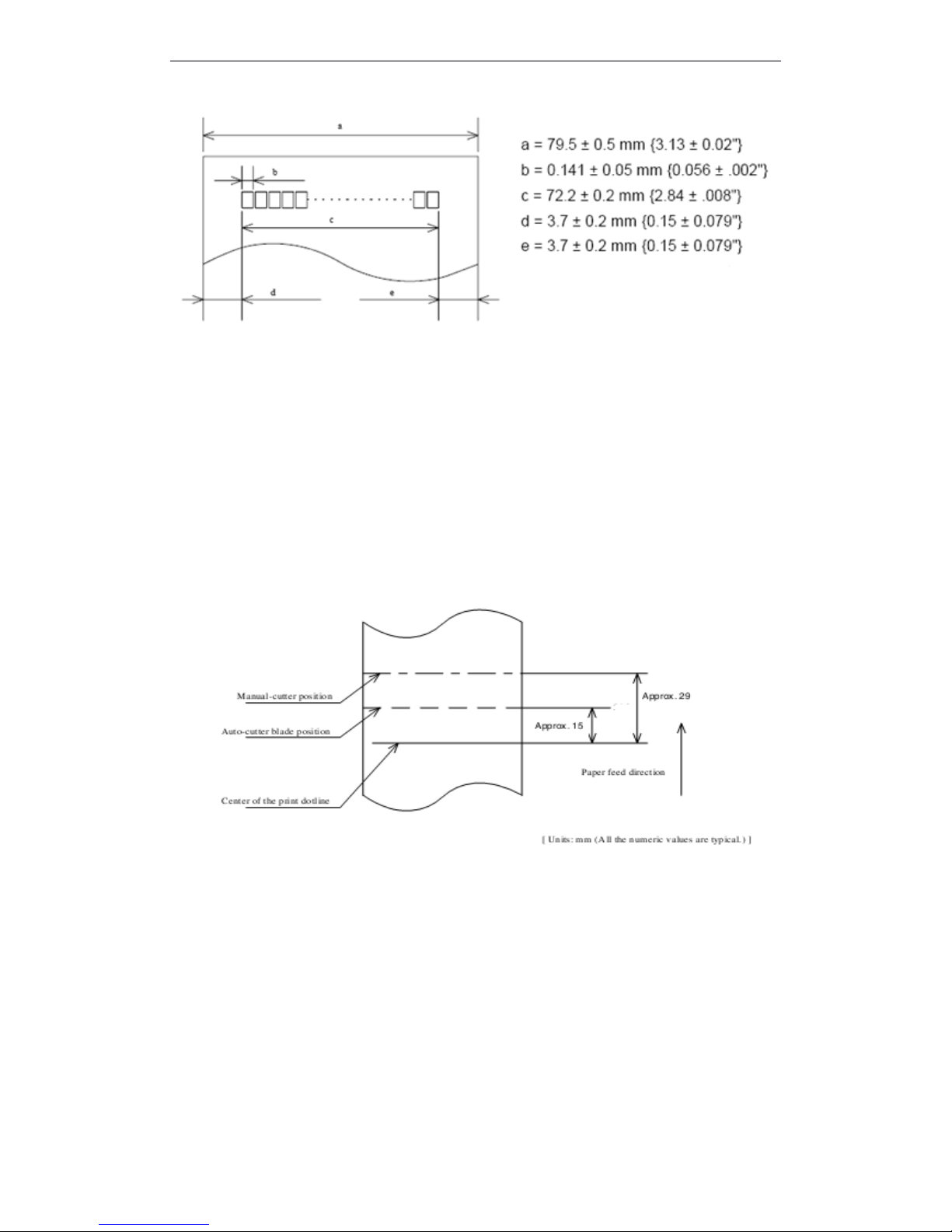
79.5 ± 0.5mm The printable area of thermal paper is 72.2 ± 0.2 mm , There are 3.7 ± 0.2 mm
blank area left and right side , as follows :
Page 8
T90 User Manual
2
1.6
1.6
1.6
1.6 Internal
Internal
Internal
Internal Buffer
Buffer
Buffer
Buffer
1 、 Receive Date Buffer Memory: 4 KB
2 、 User-defined Buffer Memory : 12KB
3 、 Macro Defined Buffer Memory : 2K
4 、 NV Bit Image BufferMemory : 256K
5 、 User-defined Commands Buffer Memory : 1K
1.7
1.7
1.7
1.7 Printing
Printing
Printing
Printing Position
Position
Position
Position and
and
and
and Tear
Tear
Tear
Tear off
off
off
off Position
Position
Position
Position
NOTE : The values shown in the figures are typical values, thevalues may vary slightly
as a result of the paper slack or variations in the paper .
1.8
1.8
1.8
1.8 Operated
Operated
Operated
Operated Specifications
Specifications
Specifications
Specifications
Power Supply : DC24V ± 7 %
1.9
1.9
1.9
1.9 Reliability
Reliability
Reliability
Reliability
1 、 Useful Time :
Thermal Print Head : 100km
Page 9
T90 User Manual
3
Autocutter : 1000000 times
1.10
1.10
1.10
1.10 Environmental
Environmental
Environmental
Environmental Specifications
Specifications
Specifications
Specifications
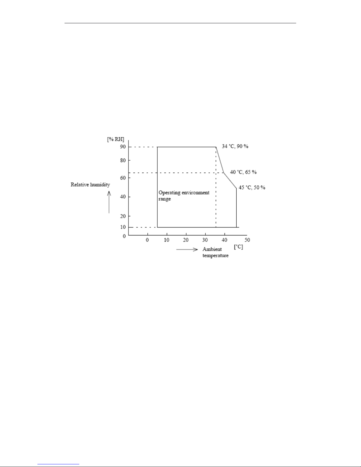
1 、 Temperature : During Operation : 5 ~ 55 ° C
During Storage : -10 ~ 50 ° C ( excludes paper )
2 、 Humidity : During Operation : 10 ~ 90 % RH
During Storage : 10 ~ 90 % RH ( excludes paper )
Figure
Figure
Figure
Figure 1.8
1.8
1.8
1.8 Operating
Operating
Operating
Operating Temperature
Temperature
Temperature
Temperature and
and
and
and Humidity
Humidity
Humidity
Humidity Range
Range
Range
Range
NOTE : If the printer d o n ’twork for a long time but installing the paper, the paper may be
go to bad and fall on print head; In such a case, before printing that must be fed
paper 30mm firstly.
Page 10

T90 User Manual
4
2
2
2
2 CONFIGURATION
CONFIGURATION
CONFIGURATION
CONFIGURATION AND
AND
AND
AND INSTALLATION
INSTALLATION
INSTALLATION
INSTALLATION
2.1
2.1
2.1
2.1 Interface
Interface
Interface
Interface Specifications
Specifications
Specifications
Specifications
2.1.1
2.1.1
2.1.1
2.1.1 RS232
RS232
RS232
RS232 Serial
Serial
Serial
Serial Interface
Interface
Interface
Interface
2.1.1.1
2.1.1.1
2.1.1.1
2.1.1.1 Specifications
Specifications
Specifications
Specifications
Data Transmission: Serial
Synchronization: Asynchronous
Hankshaking: RTS/CTS or DTR/DSR or XON/XOFF control
Signal Levels: MARK = -3 to -15 V ; Logic “ 1 ” / OFF
SPACE = +3 to +15 V ; Logic “ 0 ” / ON
Baud Rate: 115200 、 38400 、 19200 、 9600bps
Data Word Length: 8 bits
Parity: None
Stop Bits: 1 bit or more
Connector (the side on the printer ): D-SUB25 male
NOTE : Handshaking , Baud rate and Parity decided by DIP Switch 1 setting. ( refer to 3.3.1 )
the stop bits fixed on 1.
Switching between online and offline :
Th e printer have not the online and offline switch .
The printer goes o ffline :
1) Between when the power is turned on (includes re set using the interface) and when the printer
is get ready to receive the dat a .
2) During the self-test.
3) When the c over is ope n .
4) During paper feeding pushing the paper feed button.
5) Stop printing when out of paper.
6) During macro executing standby status .
7) When an error have occurred.
2.1.1.2
2.1.1.2
2.1.1.2
2.1.1.2 Interface
Interface
Interface
Interface Pin
Pin
Pin
Pin Signal
Signal
Signal
Signal Definition
Definition
Definition
Definition
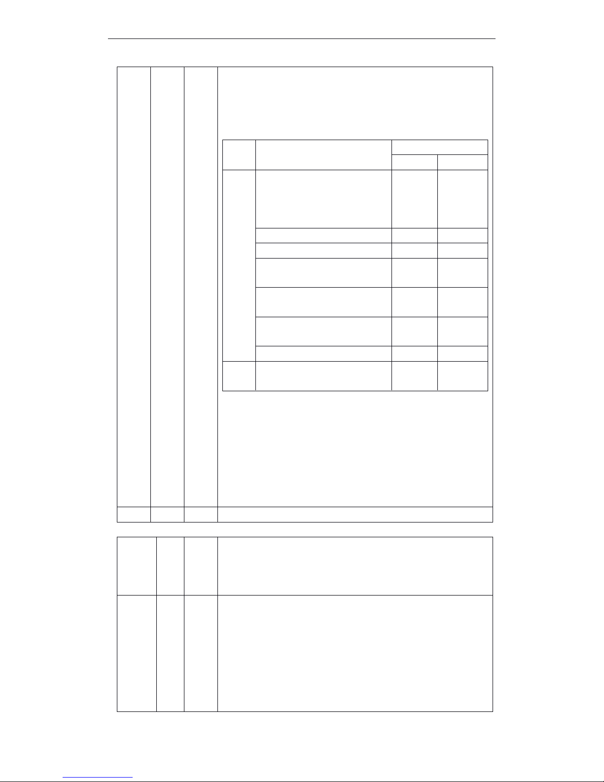
Interface connector terminal assignments and signal fuctions description as the following table
Signal assignments and functions
P in
NO.
Signal
Name
Signal
Direct
ion
Function
2
RXD
Input
Receive data
3
TXD
OutputReceive data
Page 11
T90 User Manual
5
Signal assignments and functions (continued)
4
RTS
Outpu
t
1)
When DTR/DSR control is selected , The signal indicates whether
the printer is busy. SPACE indicates that the printer get ready to
receive data,but MARK indicates that the printer is busy. Changin g
the Memory Switch setting to be used as a signal for printe r busy .
2)
3)
When XON/XOFF control is selected:
Signal indicates whether the printer is correctly connected and is
ready to receive data. SPACE indicates that the printer is ready to
receive data. The signal is always SPACE except in the following
cases :
· During the period from when the power is turned on to when the
printer is ready to receive data
· During the self-test
Printer Status
Memory SW1-3 Status
ON
OFF
Offlin
e
1.During the period from when
the power is turned on to when
the printer is ready to receive
data.
BUSY
BUSY
2. During the self-test.
BUSY
BUSY
3. When the cover is open.
—
BUSY
4. During paper feeding using the
paper feed button.
—
BUSY
5. When the printer stops
printingdue to a paper-end.
—
BUSY
6. During macro executing
standby status.
—
BUSY
7. When an error has occurred.
—
BUSY
8. When the receive buffer
becomes full.(*1)
BUSY
BUSY
7SG—
Signal ground
Pin No.
Sign
al
Nam
e
Signal
Direct
ion
Function
6
DSR
Input
This signal indicates whether the host computer can receive data.
SPACE indicates that the host computer can receive data, and MARK
indicats the host computer can ’ t receive the data.
When DTR/DSR control is selected, the printer transmits data after
confirming this
signal
( except when transmitting data by DLE EOT an d
GS a ) .
When XON/XOFF control is selected,the printer does not chec k
this signal.
Page 12
T90 User Manual
6
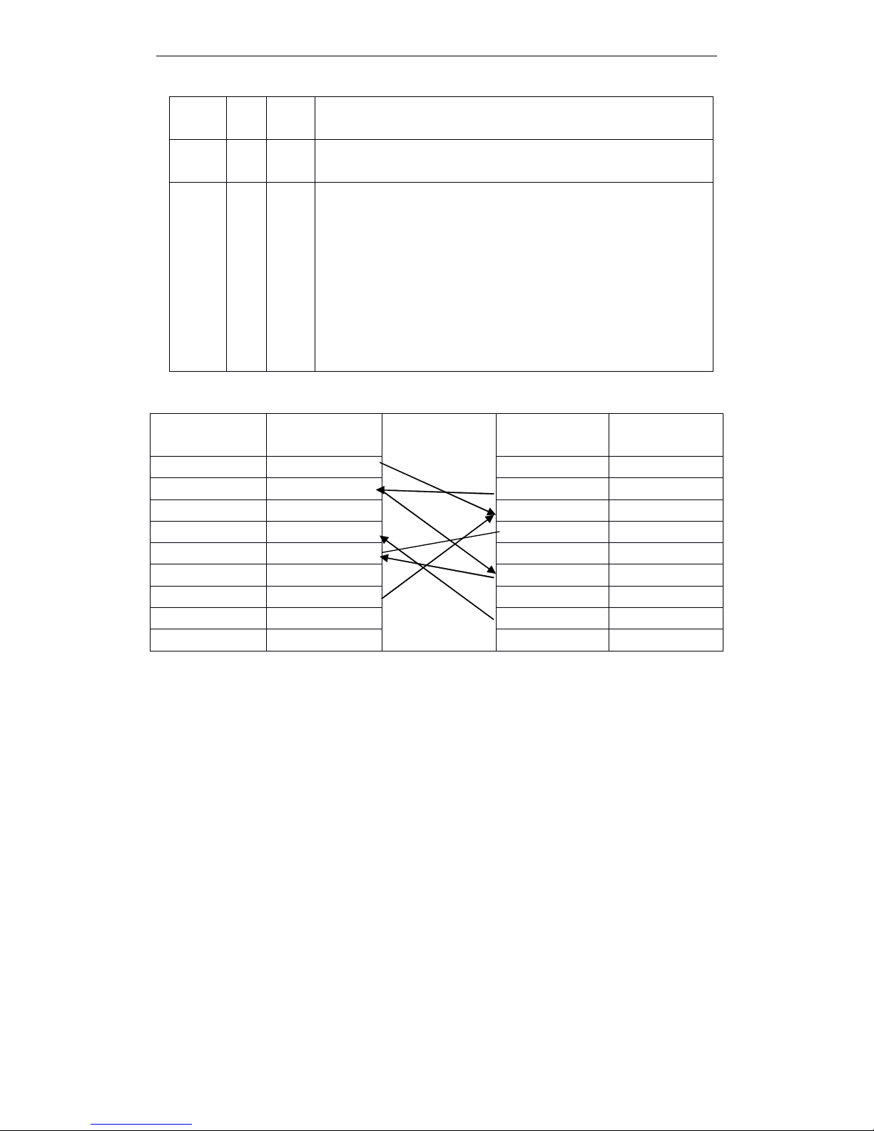
Serial interface connection example
Use the cable w ith the following signal relations.
2.1.2 IEEE
IEEE
IEEE
IEEE 1284
1284
1284
1284 Bidirectional
Bidirectional
Bidirectional
Bidirectional Parallel
Parallel
Parallel
Parallel Interface
Interface
Interface
Interface
2.1.2.1
2.1.2.1
2.1.2.1
2.1.2.1 Specifications
Specifications
Specifications
Specifications
Data Transmission : 8-bit parallel
Synchronization : Externally supplied nStrobe signals
Handshaking : nAck and busy signals
Signal Level : TTL compatible
Connector : ADS-B36BLFDR176 (Honda) or equivalent (IEEE 1284 Type B)
Switching between online and offline
The printer is not equipped with any online/offline switch. The printer is placed into offline
status in either of the followings :
1) When the power is turened on or until the printer becomes ready for data transmission
afterit is initialized by the reset signal (nlnit) from the interface.
2) During the self-test.
3) When the cover is open.
4) During paper feeding using the paper fedd button.
5) When the printer stops printing due to a paper-end(in cases when empty paper supply is
Changing the DIP switch setting enables this signal to be used as a
reset signal for the printer.
20
DTR
OutputSame as RTS signal
6
DSR
Input
This signal indicates whether the host computer can receive data.
SPACE indicates that the host computer can receive data, and MARK
indicats the host computer can ’ t receive the data.
When DTR/DSR control is selected, the printer transmits data after
confirming this
signal
( except when transmitting data by DLE EOT an d
GS a ) .
When XON/XOFF control is selected,the printer does not chec k
this signal.
Connector Pin NO.
( T90 )
Signal Name
Signal Name
Connector Pin NO .
2
TXD
DCD
1
3
RXD
TXD24
RTS
RXD
3
5
CTS
DSR46
DSR
GND57
GND
DTR68
DCD
CTS
7
20
DTR
RTS
8
Page 13
T90 User Manual
7
detected by either the paper roll end detector or the paper roll near-end detector with a
printing halt due to paper shortage enabled by ESC c 4).
6) During macro executing standby status.
7) When an error has occurred.
Reverse data mode
The status data transmission from the printer to the host is processed in the nibble or byte mode.
NOTE
NOTE
NOTE
NOTE : At
At
At
At present,
present,
present,
present, reverse
reverse
reverse
reverse data
data
data
data transmission
transmission
transmission
transmission by
by
by
by nibble.
nibble.
nibble.
nibble.
· Description
This mode allows data transmission from the asynchronous printer under the control
by the host.
Data transmissions in the Nibble mode are made via the existing control lines in units of
four bits. In the byte mode, data transmissions are proce sse d by making the eight-bit data lines
bidirectional.
The both modes fall to proce ss concurrently with the compatibility mode, thereby causing half
duplex transmission.
2.1.2.2
2.1.2.2
2.1.2.2
2.1.2.2 Interface
Interface
Interface
Interface Pin
Pin
Pin
Pin Signal
Signal
Signal
Signal Defination
Defination
Defination
Defination
Interface Pin Assignments for Each Mode
Pin
Source
Compatibility Mode
4-bits Mode
1
2
3
4
5
6
7
8
9
10
11
12
13
14
15
16
17
18
19
20
21
22
23
24
Host
Host/Ptr
Host/Ptr
Host/Ptr
Host/Ptr
Host/Ptr
Host/Ptr
Host/Ptr
Host/Ptr
Printer
Printer
Printer
Printer
Host
Printer
nStrobe
Data0(LSB)
Data1
Data2
Data3
Data4
Data5
Data6
Data7(MSB)
nAck
Busy
Perror
Select
nAutoFd
NC
GND
FG
Logic-H
GND
GND
GND
GND
GND
GND
HostClk
Data0(LSB)
Data1
Data2
Data3
Data4
Data5
Data6
Data7(MSB)
PtrClk
PtrBusy/Data3, 7
AckDataReq/Data2, 6
Xflag/Data1, 5
HostBusy
ND
GND
FG
Logic-H
GND
GND
GND
GND
GND
GND
Page 14
T90 User Manual
8
*NC: Not Connected
ND: Not Defined
NOTES : 1. A prefix “ n ” to signal names refer to low level active signals.
2. To the host provided with none of the signal lines listed above, both-way communication
fails.
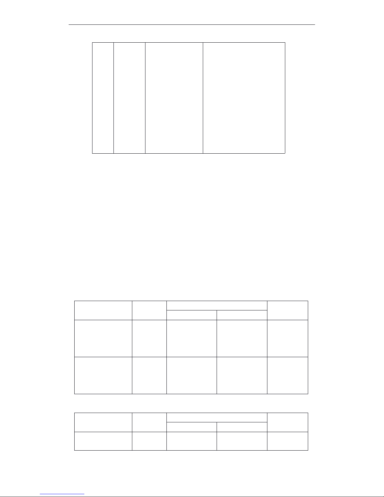
3. For interfacing, signal lines shall use twisted pair cables with the return sides connected to
signal ground level.
4. Interfacing conditions shall be all based on the TTL level to meet the following
characteristics
In addition, both rise and fall time of each signal shall be 0.5 μ s or less .
5. Data transmission shall not ignore the signal n Ack or Busy. An attempt to transmit data with
signal, nAck or Busy, ignored can cause data lose . (Data transmission for the printer shall be
made after verifying the nAck signal or while the Busy signal is at the low level.)
6. Interface cables shall be as min required short in length as possible.
Electrical
Electrical
Electrical
Electrical Characteristics
Characteristics
Characteristics
Characteristics
DC Characteristics (Except Logic- H, + 5 V signals)
Logic - H Signal Sender Characteristics
25
26
27
28
29
30
31
32
33
34
35
36
Host
Printer
Printer
Printer
Host
GND
GND
GND
GND
GND
GND
nInit
nFault
GND
DK_STATUS
+5V
nSelectIn
GND
GND
GND
GND
GND
GND
nInit
nDataAvail/Data0, 4
ND
ND
ND
1284-Active
Characteristics
Symbol
Specifications
Conditions
Min
Max
Output High Voltage
Output Low Voltage
Output High Current
Output Low Current
V
OH
V
OL
I
OH
I
OL
*2.4 V
-0.5 V
0.32 mA
-12 mA
5.5 V
*0.4 V
-
-
*IOH=0.32 mA
*IOL=-12 mA
VOH=2.4 V
VOL=0.4 V
Input High Voltage
Input Low Voltage
Input High Current
Input Low Current
V
IH
V
IL
I
IH
I
IL
2.0 V
-
-
-
-
0.8 V
-0.32 mA
12 mA
VIH=2.0 V
VIL=0.8 V
Character istics
Symbol
Specifications
Conditions
Min
Max
Output High Voltage
Output Low Voltage
V
OH
V
OL
3.0 V-5.5 V
2.0 V
While the
power is OFF
Page 15
T90 User Manual
9
+5 V Signal Sender Characteristics
** No guarantee is offered to V
OL
and IOLwhile the power is OFF.
Parallel
Parallel
Parallel
Parallel Data
Data
Data
Data Receiving
Receiving
Receiving
Receiving Timing
Timing
Timing
Timing
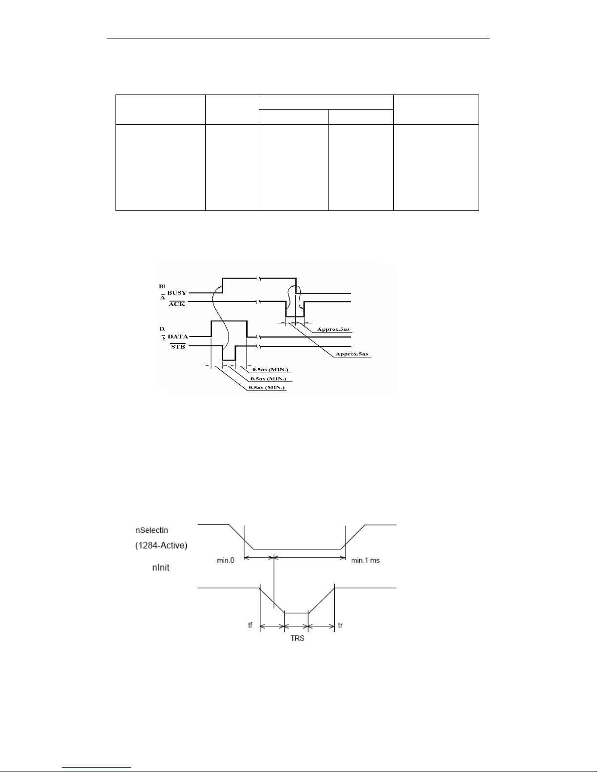
Parallel Interface Signal Timing Figure as follows(Compatibility Mode ) :
Reset
Reset
Reset
Reset the
the
the
the printer
printer
printer
printer through
through
through
through parallel
parallel
parallel
parallel interface
interface
interface
interface
To enable the printer reset by nInit signal (PIN 31) in compatibility mode. Set nInit signal by
SWITCH DIP. To enable the printer reset, meet the following signal timing.
The signal is ignored when #36 nSelectIn /1284-Active is high in reverse mode.
·
DC characteristic
TTL Level
· AC characteristic
Min reset pluse width : TRS 50 μ s (min)
NOTE : The prefix “ n ” named active-low
Reception
Reception
Reception
Reception of
of
of
of status
status
status
status from
from
from
from the
the
the
the printer
printer
printer
printer through
through
through
through the
the
the
the bidirectional
bidirectional
bidirectional
bidirectional parallel
parallel
parallel
parallel interface
interface
interface
interface
In the bidirectional parallel interface specifications, the printer status transmission isavailable by
Characteristics
Symbol
Specifications
Conditions
Min
Max
Output High Voltage
Output Low Voltage
Output High Current
Output Low Current
V
OH
V
OL
I
OH
I
OL
*2.4 V
-
-
-**
5.5 V
-**
0.32 mA
-
*IOH=0.32 mA
While the power is
OFF
VOH=2.4 V
While the power is
OFF
Page 16

T90 User Manual
10
using the both-way communication facility in the Nibble/Byte Modes in accordance with the IEEE
1284.
In this case, different from in the RS-232 serial interface apecifications, the real-time interruptions
from the printer to the host are disabled and thus precautions must be taken to the followings:
1) Allowable capacity of the printer internal buffer is 99 bytes (except ASB status), The status signals
exceeding this capacity will be discarded, To prevent possible loss of status, the host shall be
ready for data acception (Reverse Mode).
2) When ASB is used, the host is preferably in the wait state for data acception (ReverseIdle
Mode).When this state is not available, the host shall enter the Reverse Mode to always monitor the
presence of data.
3) When ASB is used, preference shall be given to the ASB status for transmission over theotherstatus
signals. Once one ASB conditions changed, all ready to send ASB conditions from last time that
need to send together, then sending the latest ASB conditi ons.
2.1.3
2.1.3
2.1.3
2.1.3 Ethernet
Ethernet
Ethernet
Ethernet Interface
Interface
Interface
Interface
2.1.3.
2.1.3.
2.1.3.
2.1.3. 1Interface
1Interface
1Interface
1Interface Specifications
Specifications
Specifications
Specifications
Ethernet Type: Standard Ethernet (10M)
TCP/IP agreement: ETHERNET, ARP, IP, TCMP, IGMP, UDP, TCP, HTTP, DHCP;
Connector Type: RJ45 (as table)
2.1.3.2
2.1.3.2
2.1.3.2
2.1.3.2 Interface
Interface
Interface
Interface Pin
Pin
Pin
Pin Signal
Signal
Signal
Signal Definition
Definition
Definition
Definition
2.1.4USB
2.1.4USB
2.1.4USB
2.1.4USB Interface
Interface
Interface
Interface
2.1.4.1
2.1.4.1
2.1.4.1
2.1.4.1 Interface
Interface
Interface
Interface Specifications
Specifications
Specifications
Specifications
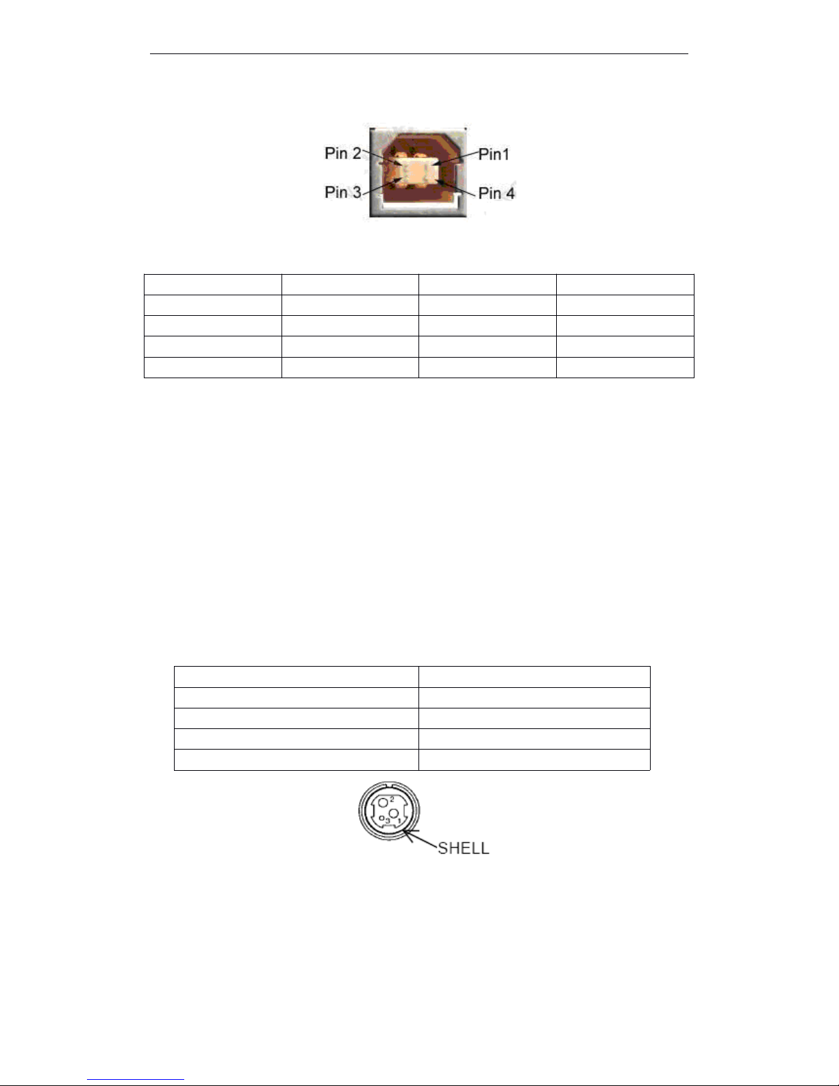
Connector Type: Type B female interfaceB
Communication Agreement: USB2.0
Pin NO.
Signal Name
Signal Source
1
TX+
Tranceive Data+ (Send signal+)
2
TX-
Tranceive Data+ -(Send signal-)
3
RX+
Receive Data+ (Receive signal+ )
4
N/C
Not connected(Blank)
5
N/C
Not connected(Blank)
6
RX-
Receive Data -(Receive signal-)
7
N/C
Not connected(Blank)
8
N/C
Not connected(Blank)
Page 17
T90 User Manual
11
2.1.4.2
2.1.4.2
2.1.4.2
2.1.4.2 Interface
Interface
Interface
Interface Pin
Pin
Pin
Pin Signal
Signal
Signal
Signal Defination
Defination
Defination
Defination
Pin Definition:
2.2
2.2
2.2
2.2 Printer
Printer
Printer
Printer Installation
Installation
Installation
Installation
2.2.1
2.2.1
2.2.1
2.2.1 Interface
Interface
Interface
Interface Connector
Connector
Connector
Connector
Refer to section 2.1 port
2.2.2
2.2.2
2.2.2
2.2.2 Power
Power
Power
Power Connector
Connector
Connector
Connector
NOTE :
To
guarantee the normal operation to the printer. Please use the standard power from our
company.
Pin Defination :
2.3
2.3
2.3
2.3 Drawer
Drawer
Drawer
Drawer Connector
Connector
Connector
Connector
T90 used RJ-11 6 connector , as follows
Pin NO.
Function
Color
Definition
1
V Bus
Red
Power +5V
2
Data-
White
Data-3Data+
Green
Data+
4
GND
Black
Ground
Pin NO.
Signal
1
+ 24
2
GND3NC
SHELL
F . G
Page 18

T90 User Manual
12
Pin Definition as the following table
Pin NO.
Signal Ground
Direction
1
Frame GND
---
2
Drawer kick-out drive signal 1
Output
3
Drawer open/close signal
Input
4
+24V
-
5
Drawer kick-out drive signal 1
Output
6
Signal GND
-
Page 19

T90 User Manual
13
3
3
3
3 FUNCTIONS
FUNCTIONS
FUNCTIONS
FUNCTIONS
3.1
3.1
3.1
3.1 List
List
List
List of
of
of
of Commands
Commands
Commands
Commands
Comman
d
Name
Command Type
Standard
Mode
Page
Mode
Executive
Set
HT
HT
HT
HT
Horizontal tab
¡¡¡
LF
LF
LF
LF
Print and line feed
¡¡¡
FF
FF
FF
FF
Print and return to standard
mode(in page mode)
¡
Ignored
¡
CR
CR
CR
CR
Print and carriage return
¡¡¡
CAN
CAN
CAN
CAN
Cancel print data in page mode
¡
Ignored
¡
DLE
DLE
DLE
DLE EOT
EOT
EOT
EOT
Transmit real-time status
¡¡¡
DLE
DLE
DLE
DLE
ENQ
ENQ
ENQ
ENQ
Send real-time request to printer
¡¡¡
ESC
ESC
ESC
ESC FF
FF
FF
FF
Print data in page mode
¡
Ignored
¡
ESC
ESC
ESC
ESC SP
SP
SP
SP
Set right-side character spacing
¡¡¡
ESC
ESC
ESC
ESC !
!
!
!
Select print modes
¡¡¡
ESC
ESC
ESC
ESC $
$
$
$
Set absolute print position
¡¡¡
ESC
ESC
ESC
ESC %
%
%
%
Select/cancel user-defined
character set
¡¡¡
ESC
ESC
ESC
ESC &
&
&
&
Define user-defined characters
¡¡¡
ESC
ESC
ESC
ESC *
*
*
*
Select bit-image mode
¡¡¡
ESC
ESC
ESC
ESC -
-
-
-
Turn underline mode on/off
¡¡¡
ESC
ESC
ESC
ESC 2
2
2
2
Select default line spacing
¡¡¡
ESC
ESC
ESC
ESC 3
3
3
3
Set line spacing
¡¡¡
ESC
ESC
ESC
ESC ?
?
?
?
Cancel user-defined characters
¡¡¡
ESC
ESC
ESC
ESC @
@
@
@
Initialize printer
¡¡¡¡ESC
ESC
ESC
ESC D
D
D
D
Set horizontal tab positions
¡¡¡
ESC
ESC
ESC
ESC E
E
E
E
Turn emphasized mode on/off
¡¡¡
ESC
ESC
ESC
ESC G
G
G
G
Turn double-strike mode on/off
¡¡¡
ESC
ESC
ESC
ESC i
i
i
i
Full cut¡¡¡ESC
ESC
ESC
ESC J
J
J
J
Print and feed paper
¡¡¡
ESC
ESC
ESC
ESC L
L
L
L
Select page mode
¡
( ¡ )
Ignored
ESC
ESC
ESC
ESC m
m
m
m
Partial cut¡¡¡ESC
ESC
ESC
ESC M
M
M
M
Select character font
¡
¡
ESC
ESC
ESC
ESC R
R
R
R
Select an international character
set¡¡
¡
ESC
ESC
ESC
ESC S
S
S
S
Select standard mode
¡
Ignored
¡
ESC
ESC
ESC
ESC T
T
T
T
Select print direction in page mode
¡▲¡
ESC
ESC
ESC
ESC V
V
V
V
Turn 90 ° clockwise rotation mode
on/off
¡¡▲
ESC
ESC
ESC
ESC W
W
W
W
Set print area in page mode
¡▲¡
Page 20

T90 User Manual
14
ESC
ESC
ESC
ESC \
\
\
\
Set relative print position
¡¡¡
ESC
ESC
ESC
ESC a
a
a
a
Select justification
¡
( ¡ )
▲
ESC
ESC
ESC
ESC c
c
c
c 3
3
3
3
Select paper sensors to output
paper-end signals
¡¡¡
ESC
ESC
ESC
ESC c
c
c
c 4
4
4
4
Select paper sensors to stop
printing¡¡
¡
ESC
ESC
ESC
ESC c
c
c
c 5
5
5
5
Enable/disable panel butons
¡¡¡
ESC
ESC
ESC
ESC d
d
d
d
Print and feed n lines
¡¡¡
ESC
ESC
ESC
ESC t
t
t
t
Select character code table
¡¡¡
ESC
ESC
ESC
ESC {
{
{
{
Turn upside-down print mode on/off
¡
( ¡ )
▲
FS
FS
FS
FS p
p
p
p
Print NV bit image
¡¡¡
FS
FS
FS
FS q
q
q
q
Define NV bit image
¡
( ¡ )¡GS
GS
GS
GS !
!
!
!
Set character size
¡¡¡
GS
GS
GS
GS $
$
$
$
Set absolute vertical print position
in page mode
¡
Ignored
¡
GS
GS
GS
GS
*
*
*
*
Define downloaded bit image
¡¡¡
GS
GS
GS
GS (
(
(
( A
A
A
A
Execute test print
¡¡Ignored
GS
GS
GS
GS (
(
(
( B
B
B
B
Set printer parameter
¡¡¡
GS
GS
GS
GS /
/
/
/
Print downloaded bit image
¡●¡
GS
GS
GS
GS :
:
:
:
Start/end macro definition
¡¡¡
¡
GS
GS
GS
GS B
B
B
B
Turn white/black reverse print
mode on/off
¡¡¡
GS
GS
GS
GS C
C
C
C 0
0
0
0
Set attribute value print mode
¡¡¡
GS
GS
GS
GS C
C
C
C 1
1
1
1
Select attribute mode(A)
¡¡¡
GS
GS
GS
GS C
C
C
C 2
2
2
2
Set attribute value
¡¡¡
GS
GS
GS
GS C
C
C
C ;
;
;
;
Select attribute mode(B)
¡¡¡
GS
GS
GS
GS H
H
H
H
Select print position of HRI
characters¡¡
¡
GS
GS
GS
GS I
I
I
I
Transmit printer ID
¡¡¡
GS
GS
GS
GS L
L
L
L
Set left margin
¡
( ¡ )▲GS
GS
GS
GS T
T
T
T
Set print position as printing origin
¡¡Ignored
GS
GS
GS
GS V
V
V
V
Select cut mode and cut paper
¡
( ¡ )¡GS
GS
GS
GS W
W
W
W
Set print area width
¡
( ¡ )
▲
GS
GS
GS
GS \
\
\
\
Set relative vertical print position in
page mode
¡
Ignored
¡
GS
GS
GS
GS ^
^
^
^
Execute macro
¡¡¡
GS
GS
GS
GS a
a
a
a
Enable/disable automatic status
back(ASB)¡¡¡¡
GS
GS
GS
GS b
b
b
b
Turn smoothing mode on/off
¡¡¡
GS
GS
GS
GS c
c
c
c
Print attribute value
¡¡¡
GS
GS
GS
GS f
f
f
f
Select font for HRI characters
¡¡¡
GS
GS
GS
GS h
h
h
h
Set bar code height
¡¡¡
GS
GS
GS
GS k
k
k
k
Print bar code
¡●¡
GS
GS
GS
GS r
r
r
r
Transmit status
¡¡¡
GS
GS
GS
GS v
v
v
v 0
0
0
0
Print grating bit image
¡●¡
Page 21

T90 User Manual
15
List of Chinese characters command
Command Type
Excutive command: The printer execute this command, it won ’ t influence the following data if
change this command.
Set command: Set the printer through the relative zonebit, the set will influence the following data.
Standard mode
¡ : Allowance
( ¡ ): To be valid when only the command locate the beginning of the line.
● : It is valid only no data in print buffer.
Page Mode
¡ : Allowance
▲ : Set data only.
Forbid : Detail with parameter as print data.
Ignored : Ignore all command codes, include parameter, do not execute any operation.
3.2
3.2
3.2
3.2 Power
Power
Power
Power Button
Button
Button
Button and
and
and
and Buttons
Buttons
Buttons
Buttons
3.2.1
3.2.1
3.2.1
3.2.1 Power
Power
Power
Power Button
Button
Button
Button
The power button designed
at
the bottom right on the front of the printer.
Turn the power off, push the power button more than 2 seconds.
NOTE : Connect the power correctly before turning the power on.
3.2.2
3.2.2
3.2.2
3.2.2 Panel
Panel
Panel
Panel Button
Button
Button
Button
3.2.2.1
3.2.2.1
3.2.2.1
3.2.2.1 Paper
Paper
Paper
Paper Feed
Feed
Feed
Feed Button
Button
Button
Button
Functions :
Push one time, the printer feed one line ( On basis of setting the line spacing, line spacing set by ES C
2 and ESC 3 command ) .
It
won ’tfeed paperatthe below conditions :
① Forbid the button function by ESC c 5.
GS w
Set bar code width
¡¡Comm
and
Name
Command Type
Standard
Mode
Page
Mode
Executive
Set
FS
FS
FS
FS !
!
!
!
Set print modes for Chinese character
¡¡¡
FS
FS
FS
FS &
&
&
&
Set Chinese characters mode
¡¡¡
FS
FS
FS
FS -
-
-
-
Turn underline mode on/off for Chinese
charcters¡¡¡FS
FS
FS
FS .
.
.
.
Cancel Chinese mode
¡¡¡
FS
FS
FS
FS 2
2
2
2
Define user-defined Chinese character
¡¡¡
FS
FS
FS
FS C
C
C
C
Select Chinese character code system
¡¡¡
FS
FS
FS
FS S
S
S
S
Set Chinese character spacing
¡¡¡
FS
FS
FS
FS W
W
W
W
Turn quadruple-size mode on/off for
Chinese characters
¡¡¡
Page 22
T90 User Manual
16
② Paper out sensor detect no paper.
· Under the condition of macro wait executive, push the feed paper button and executive the defined
macro.
· During self-test, push the button to stop self-test printing, and push once again, then continuing to print
self-test.
NOTE : ESC c 5, enable/diable the button fuction. Push button to prohibit,itisn ’tvalid.
3.3DIP
3.3DIP
3.3DIP
3.3DIP Switch
Switch
Switch
Switch
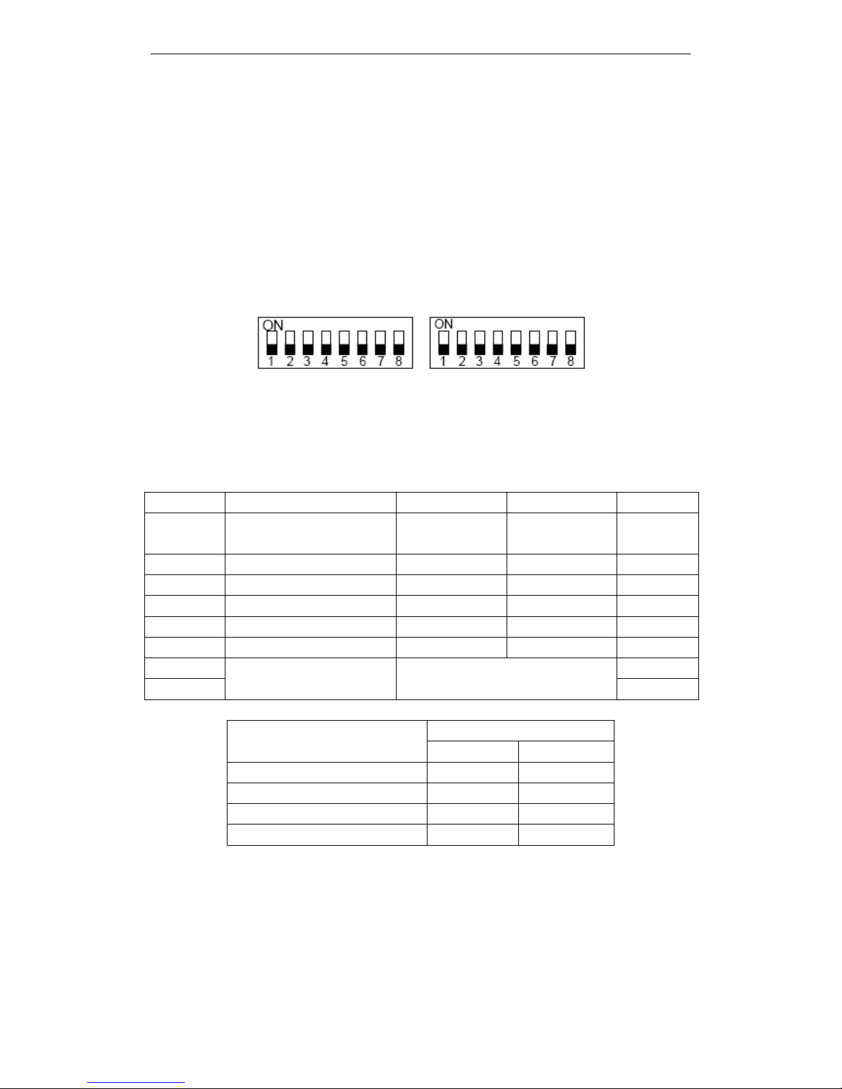
T90 designed two DIP Switchs and printed agreed number, each function refer to the below sections ;
SW1 SW2
3.3.1
3.3.1
3.3.1
3.3.1 DIP
DIP
DIP
DIP Switch
Switch
Switch
Switch 1
1
1
1
DIP Switch 1
Baud Rate Selection
NOTE : BPS – bit/second
3.3.2
3.3.2
3.3.2
3.3.2 DIP
DIP
DIP
DIP Switch
Switch
Switch
Switch 2
2
2
2
Switch
Switch
Switch
Switch NO.
NO.
NO.
NO.
Fuction
Fuction
Fuction
Fuction
ON
ON
ON
ON
OFF
OFF
OFF
OFF
Default
Default
Default
Default
1
Chinese character mode
Character mode
Chinese character
mode
OFF
2
Undefined
---
---
OFF3Undefined
---
---
OFF4Undefined
---
---
OFF5Undefined
---
---
OFF
6
Undefined
---
---
OFF
7
Serial baud rate selection
Refer to table : baud rate selection
OFF
8
OFF
Transmission Speed ( Baud rate
BPS )
Switch NO.
7
8
115200
OFF
ON
38400
OFF
OFF
19200
ON
OFF
9600
ON
ON
Page 23
T90 User Manual
17
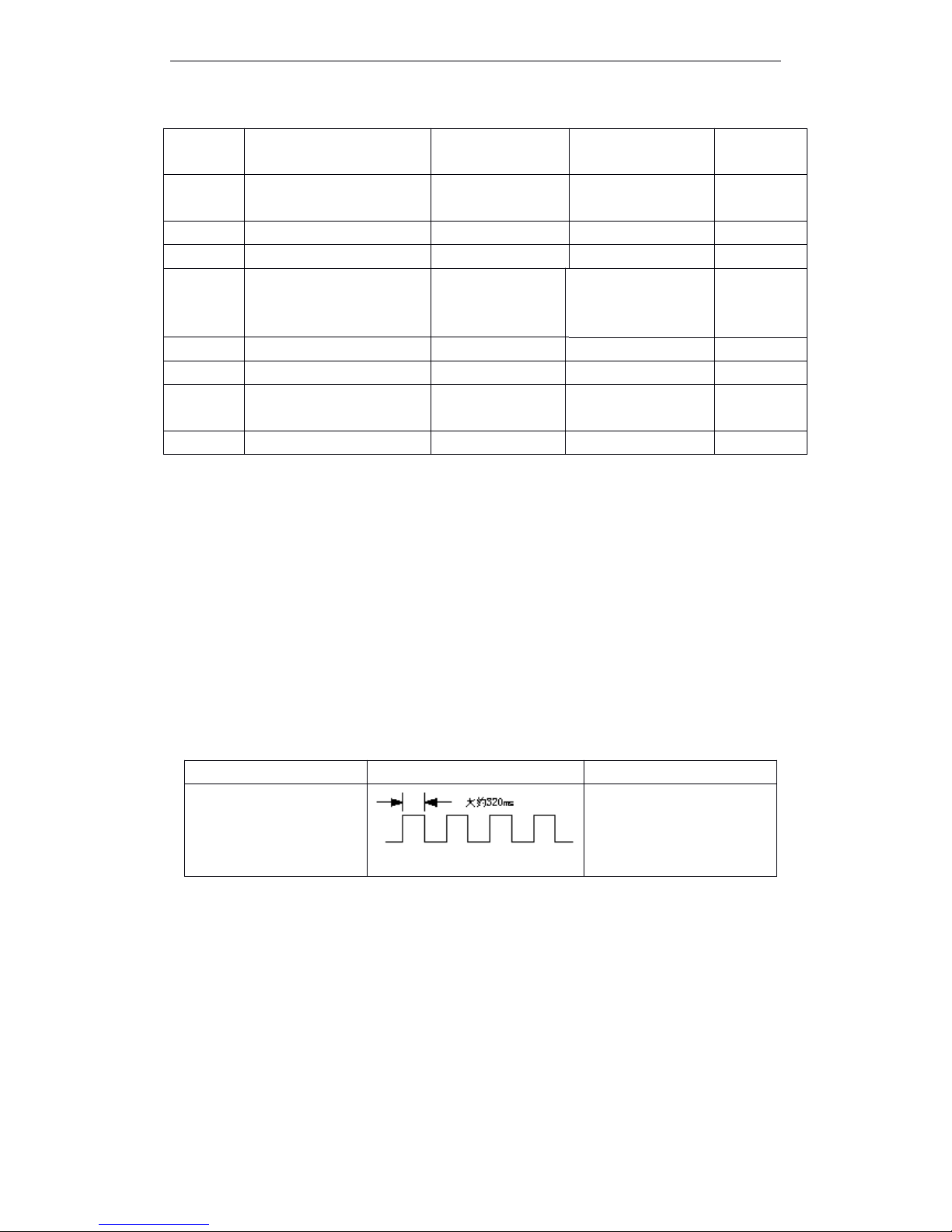
DIP Switch 2
3.4 LED/Alarm
LED/Alarm
LED/Alarm
LED/Alarm
1 ) Power LED : Green
On : Power is stable.
Off : Power is not stable.
2 ) Paper out LED : Red
On : Paper out or near-end paper.
Off : Paper is loaded ( normal condition )
Flashing : · Macro standby state
· Macro execution stanby state (When the macro execution command is used.)
Table
3.3 Standby State Indication
NOTE:A
macro can be executed r times(r specifices the number of times to execute the macro) withi n
the specified definition range. The macro can be executed continuously or can be executed by
pressing the button. If the macro is executed by pressing the FEED button, the PAPER OUT
LED bliks to indicate the macro execution ready state. ( s ee macro definition commands )
3 ) ERROR LED : Red
On : Offline (except during paper feeding using the FEED button and during test printing, and the
error state)
Off : Normal condition
Flashing : Error
4 ) Alarm LED : Blue
Flashing:Paper out, C over open, T he temperature of print head is extremely high, Autocutter error ,
Switch
Switch
Switch
Switch
NO.
NO.
NO.
NO.
Function
Function
Function
Function
ON
ON
ON
ON
OFF
OFF
OFF
OFF
Default
Default
Default
Default
1
Select print valid width
Line printing 48
characters
Line printing 42
characters
OFF
2
Select print gray leve
Deepen
Lighten
OFF3Select print paper width
Paper width 58mm
Paper width 80mm
OFF
4
Kitchen mode
Buzzer doesn ’ t
awake after paper
cut
Buzzer awake after
paper cut
OFF
5
Hex dump
Enter hex mode
Exit hex mode
OFF
6
Partial cut/full cut
Full cut
Partial cut
OFF
7
Alarm
Warn when closing
the buzzer
Warn when opening
the buzzer
OFF
8
Undefined
----
---
OFF
State
State
State
State
Paper
Paper
Paper
Paper Out
Out
Out
Out LED
LED
LED
LED Flashing
Flashing
Flashing
Flashing Pattern
Pattern
Pattern
Pattern
Recovery
Recovery
Recovery
Recovery Conditions
Conditions
Conditions
Conditions
Macro execution ready state .
Pressing the FEED button
executes the macro.
Page 24
T90 User Manual
18
another mechanism error.
Off : Printer is ready to go.
5 ) ALARM : Buzzer
Sound : Paper out, Cover open, The temperature of print head is extremely high, Autocuttererror,
Print the receipt under the back kitchen mode, another mechanism error.
Quiet : Printer is ready to go.
NOTES:
Only two times when printing each receipt under the back kitchen mode;
Other fault conditions, only 15s with sound then closing by it.
3.5
3.5
3.5
3.5 Roll
Roll
Roll
Roll Paper
Paper
Paper
Paper Cover
Cover
Cover
Cover
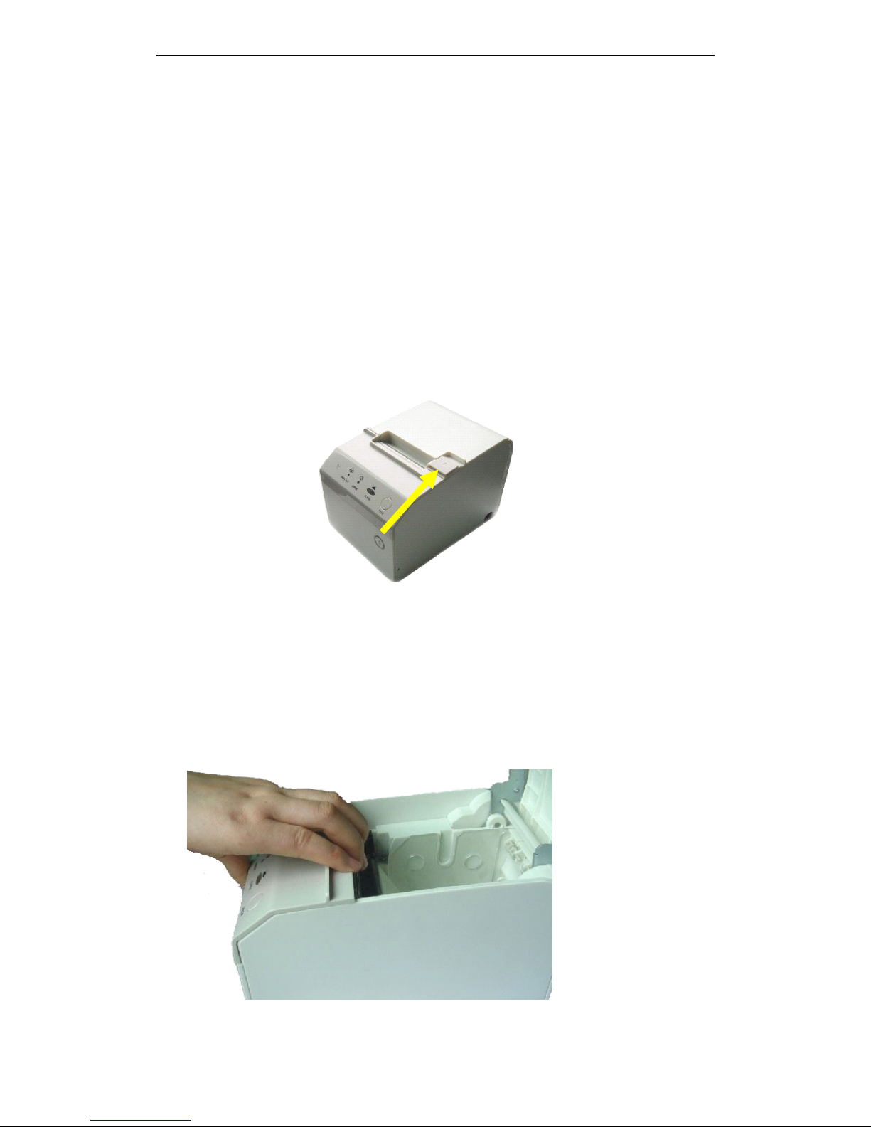
Cover button
As the following picture , pointed out direction and push the button.
3.6
3.6
3.6
3.6 Autocutter
Autocutter
Autocutter
Autocutter Reset
Reset
Reset
Reset
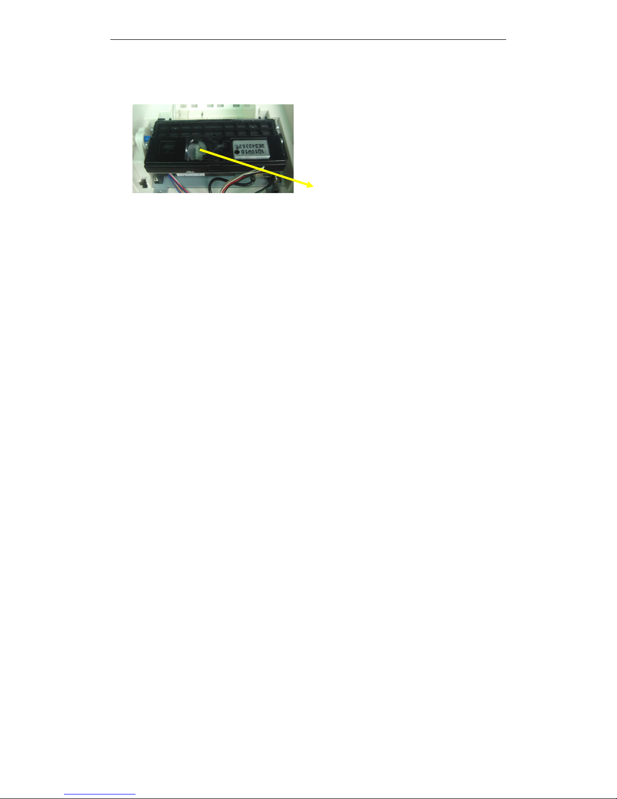
Autocutter reset, there are two directions:
1. Connect the printer again.
2. Autocutter wheel ( as following picture )
First, open the front cover as following operation (if the autocutter be jammed and don ’topen the cover,
also do like this way)
Page 25
T90 User Manual
19
Then, Turn the autocutter wheel around, doitmake the autocutter reset .
Autocutter wheel
3
3
3
3 . 7
7
7
7 Self-test
Self-test
Self-test
Self-test
Self-test that checks whether the printer is stable or not . If the self-test is correct, indicates that the
printer is stable except the interface what connect the host. Or it is unstable.
1) The printer has a self-test function that checks the followings:
· Print quality
· Inteface type and its operate conditions
·
Control software version
·
DIP Switch settings
·
Built-in character set
2) Starting the self-test
To start the self-test on a roll paper, hold down the FEED button and turn on the printer with the
cover closed, then printing the self-test list.
· Control software version
·
DIP Switch settings
· A rolling pattern using only the built-in character set
· A partial cut after completing the test printing
3
3
3
3 . 8HexDump
8HexDump
8HexDump
8HexDump
1 ) Hexadecimal print function
This function prints the data transmitted from the host computer in hexadecimal numbers and in
its corresponding characters.
2 ) Starting hexadecimal printing
Starting hexadecimal printing has two ways:
- DIP switch setting : In the DIP-SW2 Function, SW-5 is “ ON ”
- Execute Command GS
GS
GS
GS (
(
(
( A
A
A
A
The printer first prints “ Hexadecimal Dump ” on roll paper and prints the received printdata in
hexadecimal numbers and in its corresponging characters.
NOTES
NOTES
NOTES
NOTES : 1. If no characters correspond to the data received, the printer prints “ . ” .
2.During hexadecimal dumping, any commands other than DLE EOT、DLE ENQ a nd
DLE DC4 do not function.
3 . Insufficent print data to fill the last line can be printed by setting te printer offline (for
Page 26
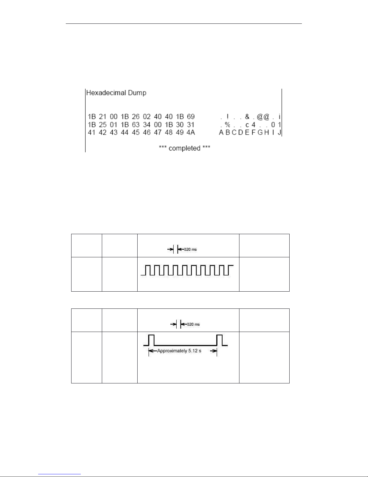
T90 User Manual
20
example: push the feed paper button down).
3 ) Ending hexadecimal dumping
Hexadecimal printing ends by setting SW-5
is
“ OFF ” in DIP-SW2 function, resetting the printer,
push down button three times (but returning to hexadecimalatonce).
< Printing example >
3
3
3
3 . 9
9
9
9 Error
Error
Error
Error Processing
Processing
Processing
Processing
3
3
3
3 . 9
9
9
9 . 1
1
1
1 Error
Error
Error
Error Type
Type
Type
Type
1)
1)
1)
1) Error
Error
Error
Error that
that
that
that automatically
automatically
automatically
automatically recover
recover
recover
recover
Errors That Automatically Recover
2)
2)
2)
2) Errors
Errors
Errors
Errors that
that
that
that have
have
have
have the
the
the
the possibility
possibility
possibility
possibility of
of
of
of recovery
recovery
recovery
recovery
Errors That Can Possibly Recover
3
3
3
3 . 9
9
9
9 . 2
2
2
2 Printer
Printer
Printer
Printer Operation
Operation
Operation
Operation When
When
When
When an
an
an
an Error
Error
Error
Error Occurs
Occurs
Occurs
Occurs
The printer executes the following operations when detecting an error.
· Stop s all printer operations for the selected paper section.
Error
Error
Error
Error
Description
Description
Description
Description
Error
Error
Error
Error LED
LED
LED
LED Flashing
Flashing
Flashing
Flashing Pattern
Pattern
Pattern
Pattern
Recovery
Recovery
Recovery
Recovery
Print head
over-
temperat
ure error
Print head
temperatur
e is over
57 ° C
Recovers
automatically when
the print head is
below 45 ° C.
Error
Error
Error
Error
Description
Description
Description
Description
Error
Error
Error
Error LED
LED
LED
LED Flashing
Flashing
Flashing
Flashing Pattern
Pattern
Pattern
Pattern
Recovery
Recovery
Recovery
Recovery
Autocutter
error
The
autocutter
does not
work
correctly
If paper jams, after
solving this
problem, then
recovering by DLE
DLE
DLE
DLE
ENQ
ENQ
ENQ
ENQ 1
1
1
1 or DLE
DLE
DLE
DLE
ENQ
ENQ
ENQ
ENQ 2
2
2
2
Page 27

T90 User Manual
21
· Goes BUSY.
· Blinks the ERROR LED.
3
3
3
3 . 9
9
9
9 . 3
3
3
3 Date
Date
Date
Date Receive
Receive
Receive
Receive Error
Error
Error
Error
If one of the following errors during serial interface communication, the printer prints “ ? ” or
ignores the data.
3
3
3
3 . 10
10
10
10 Status
Status
Status
Status Conditions
Conditions
Conditions
Conditions
The printer has the following two roll paper status condition sensor:
1 ) Roll paper end sensor
The sensor which detects whether paperispresent or not. When the sensor detects a paper-end,
the printer stops printing.
2 ) Roll paper near-end sensor
The sensor which detects a near-end of a paper roll.
When the paper roll diameter becomes sufficiently small, the detects a near-end of the paper roll
and the PAPER OUT LED lights. If the sensorisenabled by ESC c4,the printer stops printing.
NOTES : · Install the new roll paper and close the cover, the printer start to printer again.
· Paper near-end sensor ready by user.
3.11
3.11
3.11
3.11 Buffer-Full
Buffer-Full
Buffer-Full
Buffer-Full Printing
Printing
Printing
Printing
After the printer deal with one line dates in the buffer area, When the printer receive the continued date,
the printer will automatically print the processed date and feed paper one line (under the standard mode).
3 .12
.12
.12
.12 Page
Page
Page
Page Mode
Mode
Mode
Mode
3.12.1
3.12.1
3.12.1
3.12.1 Description
Description
Description
Description
The printer has two operate modes (only at the conditions of selecting the roll paper as the source of
roll paper):the standard mode and the page mode. Under the standard mode, The printer prints and fee d
paper after receiving the data and command of feed paper every time. Under the page mode, the printing
data and the command of feed paper which received by the printer are dealed with and dep osit at the
one special memory, and the printer does not any operations. After receiving the ESC FF or FF
command, all deposit data will be printed.
For example : Under standard mode, after receiving the data of ” ABCDEF ” <LF> , the printer prints the
characters ” ABCDEF ” and feed paper one line. Under the page mode, ” ABCDEF ” be written to the
special print data area in the memory, meanwhile the print area of the next print data in the data area
will move down one line.Topage mode by ESC L command, after all data and commands dealed with
Page 28
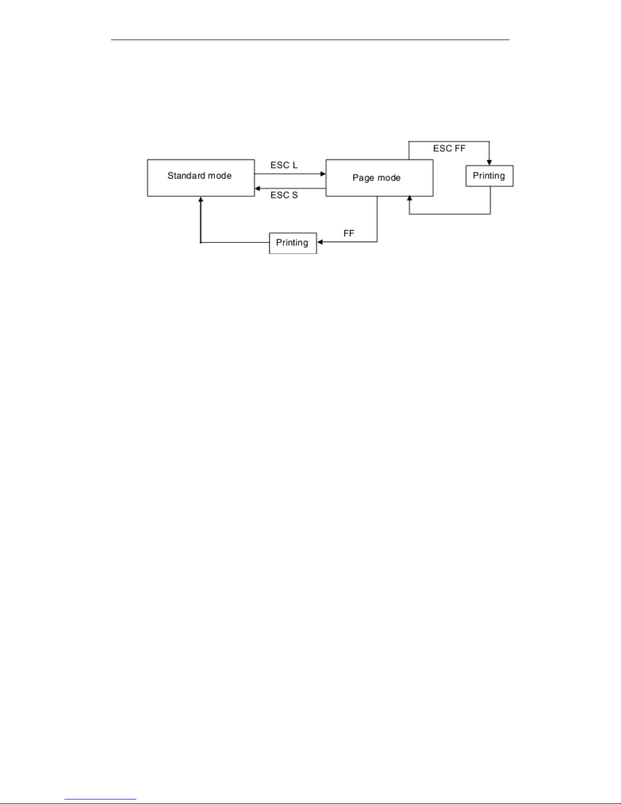
T90 User Manual
22
page mode. Print all received data by ESC FF command , but execute FF command, after printing all
data, the printer return to the standard mode. Execute ESC S command, the printer return to the
standard mode directly, but do not print the received data which received under the page mode, these
data will be de lected from memory.
3.12.2
3.12.2
3.12.2
3.12.2 Set
Set
Set
Set Value
Value
Value
Value under
under
under
under the
the
the
the Standard
Standard
Standard
Standard Mode
Mode
Mode
Mode and
and
and
and Page
Page
Page
Page Mode
Mode
Mode
Mode
1 ) Set the commands the same as parameters under the standard mode and page mode. But ESC
SP,
ESC
2,
ESC 3 command could be set the different values under the standard mode and page mode,
the different set value under the each mode will be remembered.
2 ) Under the standard mode, if use the 82.5mm paper width, when printing dot image, the max printable
widthis640 dots ; but the same roll paper under the page mode that will be printed 664 dotsatthe
direction of Y (feed paper direction) (the above that need to set as follows : set Y direction by SC W
command, and the print areais664 dots , Set 1 or 3 as the print direction parameter n by ESC T
command .)
3.12.3
3.12.3
3.12.3
3.12.3 Data
Data
Data
Data Print
Print
Print
Print Mode
Mode
Mode
Mode i
i
i
i n
n
n
n the
the
the
the Print
Print
Print
Print Area
Area
Area
Area
The data in the print area will be executed as the fllowing description :
1 、 Set the print area by ESC W command , before the printer receives the ESC W command , The
started position (x0, y0) on the
left
( the operator face to the printer
) ,
the print area
at
the extende d
length(d xdots) x(dy dots) at the X direction, at the Y direction to extend the length(feed paper
direction), If do not use ESC w to point , the print area keep silence.
2 、 Point the set position by ESC w command, and set the print direction by ESC
T,
the print data
printsatthe appointed area, 3.11.2 the first point, meansatthe default conditions.
The print data include the down-load dot image and bar code, dot image data
at
the point of the left
bottom
( 3.11.3 the second point)will be in line
at
the bottom, but all HRI characters are printed und er
the bottom line.
Under this (3.11.3 point 2) circumstancesm, If the height of characters over the stable height or
receive the download dot image data,any part which over the stable height can not be printed.
3 、 Not any setting
commands
( for example: LF or ESC J)which includes feed paper one line to print, If
date(include the spacing of the right side) which over the printing area, the printer in printing area
which will be fed paper one line.
Or,
the printing position will be moved to the initial position of the
next line, the lines of feed paper decided on setting the relative parameters ( For example : ESC 2
、
ESC 3 ) .
Page 29

T90 User Manual
23
4 、 Under default circumstances, the line width spacingis4.23mm
( 1/6 inch),the widthis30 dots. If t he
date in the next line printing dateishigher than the height of double printing, then the dot image will
be had two linesor more, bar codeishigher than the stable characters, the total lines of feed paper
is
not enough, leed to overlapping printing.Tosolve this promble to extend the line spacing, At the
section 3.1 1.4, the line specingis27 dots or more.
For example: Print one map of dot image which have 6 bytes in the vertical direction, do as the
following solutions:
Dot ( 8 × 6 ) in the vertical direction - 21 dots when starting feed paper in the printarea ×
Exchangeable unit ( 360/180 ) in the vertical direction=54
The line spacingis27 dots ( the heightis54 dots
) ,
need to feed paper.
Use
Use
Use
Use the
the
the
the following
following
following
following commands:
commands:
commands:
commands:
ESC
ESC
ESC
ESC W
W
W
W xL,
xL,
xL,
xL, xH,
xH,
xH,
xH, yL,
yL,
yL,
yL, yH,
yH,
yH,
yH, dxL,
dxL,
dxL,
dxL, dxH,
dxH,
dxH,
dxH, dyL,
dyL,
dyL,
dyL, dyH
dyH
dyH
dyH
ESC
ESC
ESC
ESC T
T
T
T n
n
n
n
ESC
ESC
ESC
ESC 3
3
3
3 54
54
54
54 Extend
Extend
Extend
Extend the
the
the
the line
line
line
line spacing
spacing
spacing
spacing
LF
LF
LF
LF
GS
GS
GS
GS /
/
/
/ 1
1
1
1
ESC
ESC
ESC
ESC 2
2
2
2 The
The
The
The line
line
line
line spacing
spacing
spacing
spacing recovers
recovers
recovers
recovers to
to
to
to default
default
default
default ( 1/6
1/6
1/6
1/6 inch
inch
inch
inch )
NOTE : The vertical dot densityis1/380, level dot densityis1/180. The position of variable definition
is
decided by the printing direction, Set the dot density 1/180 by GS p in the vertical direction, can
not change the present printing position.
Page 30
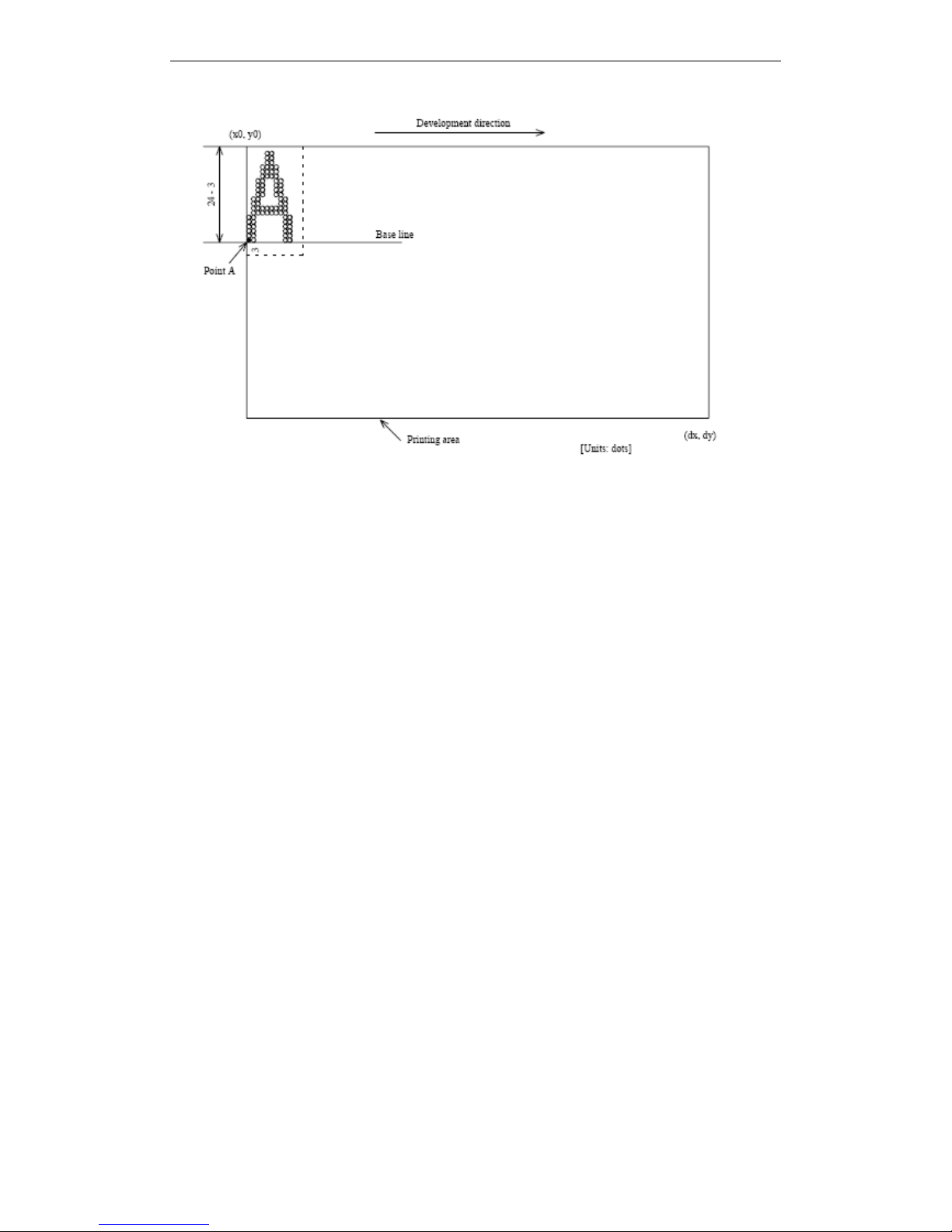
T90 User Manual
24
Figure
Figure
Figure
Figure 3.11.2
3.11.2
3.11.2
3.11.2 Character
Character
Character
Character Data
Data
Data
Data Initial
Initial
Initial
Initial Position
Position
Position
Position
Page 31
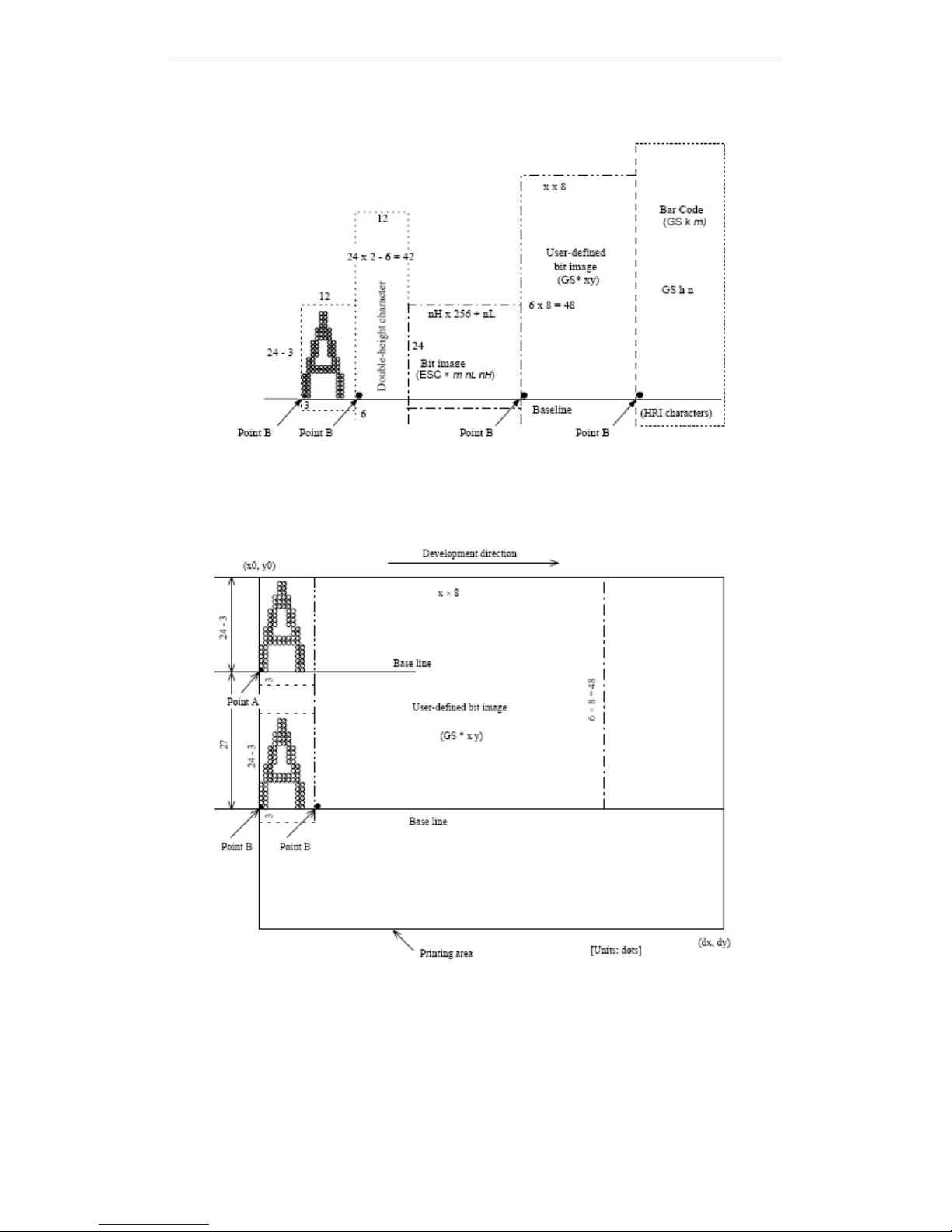
T90 User Manual
25
Figure
Figure
Figure
Figure 3.11.3
3.11.3
3.11.3
3.11.3 Printing
Printing
Printing
Printing Data
Data
Data
Data Initial
Initial
Initial
Initial Position
Position
Position
Position
Figure
Figure
Figure
Figure 3.11.4
3.11.4
3.11.4
3.11.4 Download
Download
Download
Download Dot
Dot
Dot
Dot Image
Image
Image
Image Initial
Initial
Initial
Initial Position
Position
Position
Position
Page 32
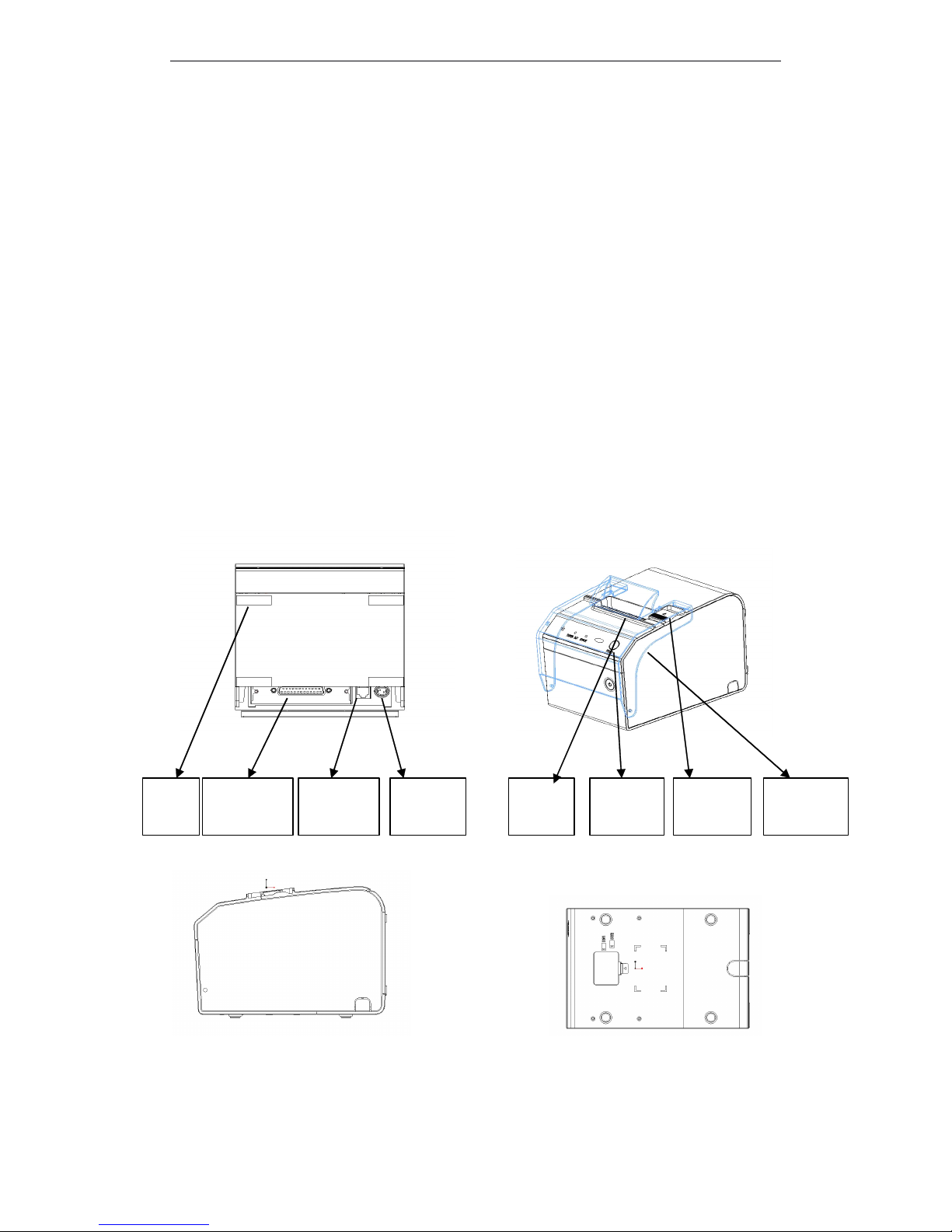
T90 User Manual
26
4
4
4
4 CASE
CASE
CASE
CASE SPECIFICATIONS
SPECIFICATIONS
SPECIFICATIONS
SPECIFICATIONS
4.1
4.1
4.1
4.1 External
External
External
External Dimensions
Dimensions
Dimensions
Dimensions and
and
and
and Mass
Mass
Mass
Mass
Height : 152mm
Width : 145mm
Depth : 220mm
Mass : 2320g ( except for a roll paper )
4.2
4.2
4.2
4.2 Color
Color
Color
Color
White 、 Black 、 Gray
4.3
4.3
4.3
4.3 External
External
External
External Appearance
Appearance
Appearance
Appearance
Figure
Figure
Figure
Figure 1
1
1
1 : T90
T90
T90
T90 Back
Back
Back
Back Figure
Figure
Figure
Figure 2
2
2
2 : T90
T90
T90
T90 Plan
Plan
Plan
Plan
Figure
Figure
Figure
Figure 3
3
3
3 : T90
T90
T90
T90 Side
Side
Side
Side Figure
Figure
Figure
Figure 4
4
4
4 : T90
T90
T90
T90 Underside
Underside
Underside
Underside
Paper
Cover
Keyboar
d
Paper
out
Oil-proof
Dataline
Interface
Cash
Interface
Power
Interface
Foot
Pad
Page 33

T90 User Manual
27
5
5
5
5 COMMANDS
COMMANDS
COMMANDS
COMMANDS
5.1 Command Notation
[Name] The name of the command
[Format] The code sequence
[ ] k indicates the contents in brackets [ ] should be repeated k time.
[Range] Gives the variable allowable ranges
[Description] Describes the function of the command.
[Particularize] Goes into particular use of commands.
[Notes] Provides important information on setting and using the printer command,
if necessary.
[Default] Gives the default values, if the commands with the parameters.
[Reference] List the interrelated commands.
The data signed by < >H, is hexadecimal.
The data signed by < >B , is binary.
5.2 Explanation of Terms
(1) Receive buffer
The receive buffer is used to store data from the host computer. All received data is
stored in this buffer and processed in the order received.
(2) Print buffer
The print buffer is used to store image data for printing.
(3) Full printing buffer area
The printer buffer is full. When the printer buffer is full, if new printing data comings,
the data in the printing buffer area to be printed, and execute the operation of
exchanging the line. The operation the same as the LF commands.
(4) Initial position of line
Initial positon of line conditions meets the folling points:
l No printing data in the present printing buffer area (includes part empty data which
caused by blank and HT command)
l Appoints the printing position that have not through ESC $ or ESC \ commands.
(5) Printable area
The maximum printable area of this printer is as follows:
① Standard mode, horizontal direction:
About 72.2mm
② Page mode , horizontal direction:
About 72.2mm
③ Page mode, vertical direction:
About 117.3mm
(6) Print area
The print area set by commands, the print are £ printable area.
(7) Ignored
All commands in this condition, include the parameters which be read, then discarding ,
but do not any operations.
(8) Inch
Length unit. 1 inch=25.4mm.
Page 34
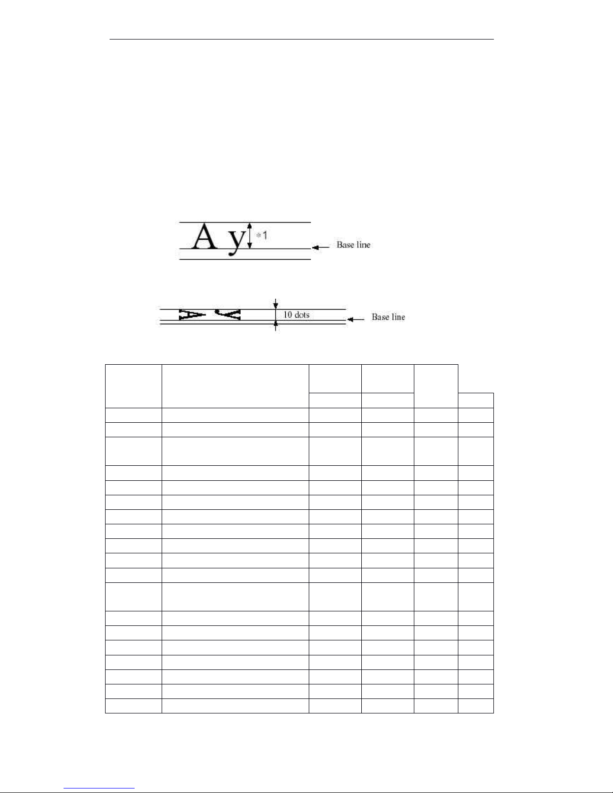
T90 User Manual
28
(9) MSB
Most Significant Bit
(10) LSB
Least Significant Bit
(11)Baseline
The standard position of the characters data which be stroed in the print buffer
area.The following indicates the general characters position under the standard
mode and page mode:
*1 When selecting character
font A, the width is 21 dots
When selecting character
B, the width is 16 dots.
Rotate the characters under the standard mode: ( only when selecting the font A )
5.3 List of Commands
Commands
Name
Command
s Type
Standard
Mode
Page
Mode
Execute
Set
HT
HT
HT
HT
Horizontal tab
¡¡¡
LF
LF
LF
LF
Print and line feed
¡¡¡
FF
FF
FF
FF
Print and return to standard mode(in
page mode)
¡
Ignored
¡
CR
CR
CR
CR
Print and carriage return
¡¡¡
CAN
CAN
CAN
CAN
Cancel print data in page mode
¡
Ignored
¡
DLE
DLE
DLE
DLE EOT
EOT
EOT
EOT
Transmit real-time request to printer
¡¡¡
DLE
DLE
DLE
DLE ENQ
ENQ
ENQ
ENQ
Send real-time request to printer
¡¡¡
ESC
ESC
ESC
ESC FF
FF
FF
FF
Print data in page mode
¡
Ignored
¡
ESC
ESC
ESC
ESC SP
SP
SP
SP
Set right-side charcter spacing
¡¡¡
ESC
ESC
ESC
ESC !
!
!
!
Select print modes
¡¡¡
ESC
ESC
ESC
ESC $
$
$
$
Set absolute print position
¡¡¡
ESC
ESC
ESC
ESC %
%
%
%
Select/cancel user-defined
character set
¡¡¡
ESC
ESC
ESC
ESC &
&
&
&
Define user-defined characters
¡¡¡
ESC
ESC
ESC
ESC *
*
*
*
Select bit-image mode
¡¡¡
ESC
ESC
ESC
ESC -
-
-
-
Turn underline mode on/off
¡¡¡
ESC
ESC
ESC
ESC 2
2
2
2
Select default line spacing
¡¡¡
ESC
ESC
ESC
ESC 3
3
3
3
Set line spacing
¡¡¡
ESC
ESC
ESC
ESC ?
?
?
?
Cancel user-defined characters
¡¡¡
ESC
ESC
ESC
ESC @
@
@
@
Initialize printer
¡¡¡
¡
Page 35

T90 User Manual
29
ESC
ESC
ESC
ESC D
D
D
D
Set horizontal tab positions
¡¡¡
ESC
ESC
ESC
ESC E
E
E
E
Turn emphasized mode on/off
¡¡¡
ESC
ESC
ESC
ESC G
G
G
G
Turn double-strike mode on/off
¡¡¡
ESC
ESC
ESC
ESC i
i
i
i
Full cut¡¡¡ESC
ESC
ESC
ESC J
J
J
J
Print and feed paper
¡¡¡
ESC
ESC
ESC
ESC L
L
L
L
Select page mode
¡
( ¡ )
IgnoredESC
ESC
ESC
ESC m
m
m
m
Partial cut
¡¡¡
ESC
ESC
ESC
ESC M
M
M
M
Select character font
¡
¡
ESC
ESC
ESC
ESC R
R
R
R
Select an international character set
¡¡¡
ESC
ESC
ESC
ESC S
S
S
S
Select standard mode
¡
Ignored
¡
ESC
ESC
ESC
ESC T
T
T
T
Select print direction in page mode
¡▲¡
ESC
ESC
ESC
ESC V
V
V
V
Turn 90 ° clockwise rotation mode
on/off¡¡
▲
ESC
ESC
ESC
ESC W
W
W
W
Set print area in page mode
¡▲¡
ESC
ESC
ESC
ESC \
\
\
\
Set relative print position
¡¡¡
ESC
ESC
ESC
ESC a
a
a
a
Select justification
¡
( ¡ )
▲
ESC
ESC
ESC
ESC c
c
c
c 3
3
3
3
Select paper sensors to output
paper-end signals
¡¡¡
ESC
ESC
ESC
ESC c
c
c
c 4
4
4
4
Select paper sensors to stop
printing¡¡
¡
ESC
ESC
ESC
ESC c
c
c
c 5
5
5
5
Enable/disable panel buttons
¡¡¡
ESC
ESC
ESC
ESC d
d
d
d
Print and feed n lines
¡¡¡
ESC
ESC
ESC
ESC t
t
t
t
Select character code tables
¡¡¡
ESC
ESC
ESC
ESC {
{
{
{
Turn upside-down print mode on/off
¡
( ¡ )▲FS
FS
FS
FS p
p
p
p
Write to NV bit image
¡¡¡
FS
FS
FS
FS q
q
q
q
Define to NV bit image
¡
( ¡ )¡GS
GS
GS
GS !
!
!
!
Selet character size
¡¡¡
GS
GS
GS
GS $
$
$
$
Set absolute vertical print position in
page mode
¡
Ignored
¡
GS
GS
GS
GS
*
*
*
*
Define download bit image
¡¡¡
GS
GS
GS
GS (
(
(
( A
A
A
A
Execute test print
¡
¡
IgnoredGS
GS
GS
GS /
/
/
/
Print download bit image
¡●¡
GS
GS
GS
GS :
:
:
:
Start/end macro definition
¡¡¡
¡
GS
GS
GS
GS B
B
B
B
Turn white/black reverse print mode
on/off¡¡
¡
GS
GS
GS
GS C
C
C
C 0
0
0
0
Set attribute value print mode
¡¡¡
GS
GS
GS
GS C
C
C
C 1
1
1
1
Select attribute mode(A)
¡¡¡
GS
GS
GS
GS C
C
C
C 2
2
2
2
Set attribute value
¡¡¡
GS
GS
GS
GS C
C
C
C ;
;
;
;
Select attribute mode(B)
¡¡¡
GS
GS
GS
GS H
H
H
H
Select print position of HRI
characters¡¡
¡
GS
GS
GS
GS I
I
I
I
Transmit printer ID
¡¡¡
GS
GS
GS
GS L
L
L
L
Set left margin
¡
( ¡ )
▲
Page 36
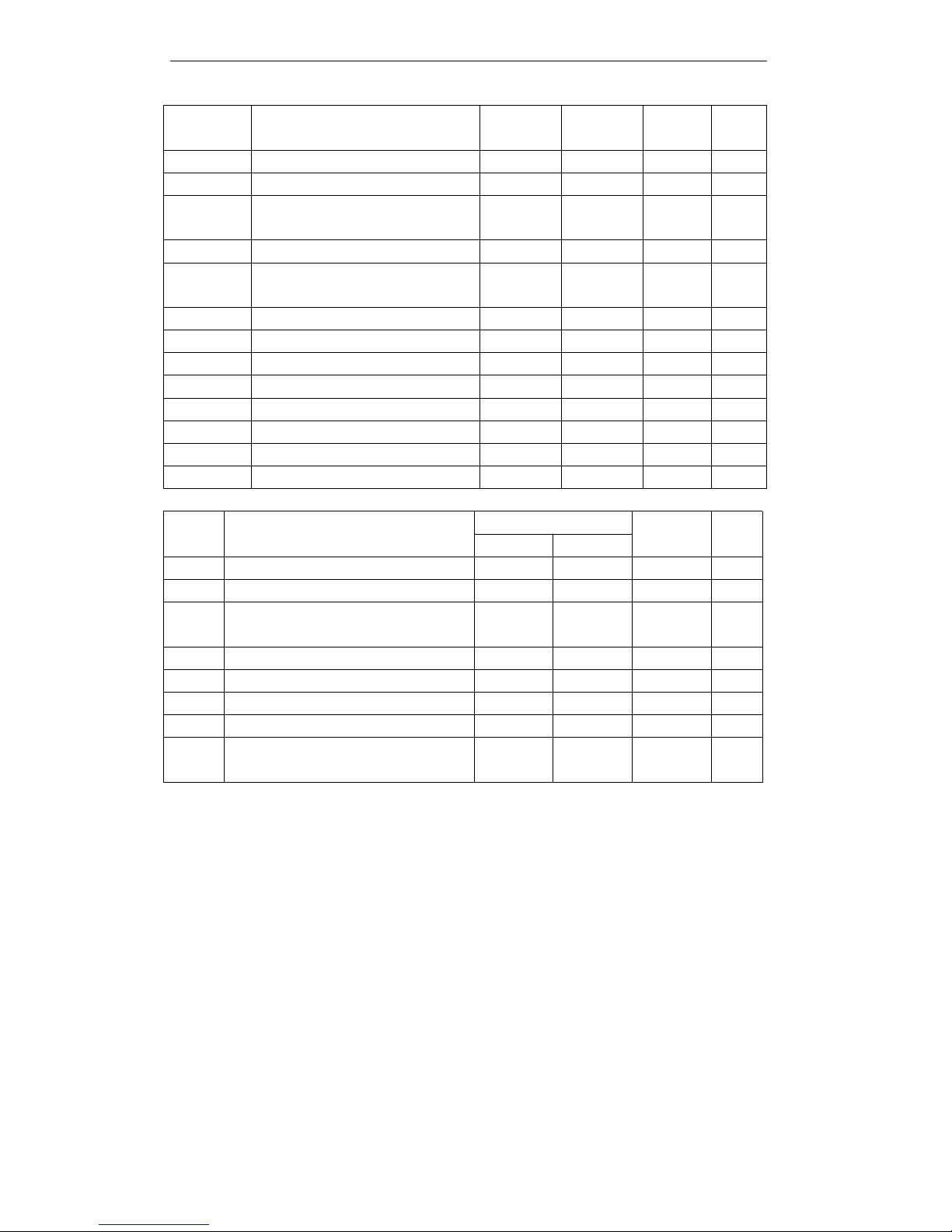
T90 User Manual
30
List of Chinese characters command
Command Type
Excutive command: The printer execute this command, it won ’ t influence the following data if
change this command.
Set command: Set the printer through the relative zonebit, the set will influence the following
data.
Standard mode
¡ : Allowance
( ¡ ): To be valid when only the command locate the beginning of the line.
● : It is valid only no data in print buffer.
Page Mode
¡ : Allowance
▲ : Set data only.
Forbid : Detail with parameter as print data.
Ignored : Ignore all command codes, include parameter, do not execute any operation.
GS
GS
GS
GS T
T
T
T
Set print position as printing origin
¡¡IgnoredGS
GS
GS
GS V
V
V
V
Selct out mode and cut paper
¡
( ¡ )
¡
GS
GS
GS
GS W
W
W
W
Set print area width
¡
( ¡ )
▲
GS
GS
GS
GS \
\
\
\
Set relative vertical print position in
page mode
¡
Ignored
¡
GS
GS
GS
GS ^
^
^
^
Execute macro
¡¡¡
GS
GS
GS
GS a
a
a
a
Enable/disable automatic status
back(ASB)¡¡¡¡
GS
GS
GS
GS b
b
b
b
Turn smoothing mode on/off
¡¡¡
GS
GS
GS
GS c
c
c
c
Print attribute value
¡¡¡
GS
GS
GS
GS f
f
f
f
Select font for HRI characters
¡¡¡
GS
GS
GS
GS h
h
h
h
Set bar code height
¡¡¡
GS
GS
GS
GS k
k
k
k
Print bar code
¡●¡
GS
GS
GS
GS r
r
r
r
Transmit status
¡¡¡
GS
GS
GS
GS v
v
v
v 0
0
0
0
Print grating bit image
¡●¡
GS
GS
GS
GS w
w
w
w
Set bar code width
¡¡Comm
and
Name
Command Type
Standard
Mode
Page
Mode
Executive
Set
FS
FS
FS
FS !
!
!
!
Set print modes for Chinese character
¡¡¡
FS
FS
FS
FS &
&
&
&
Set Chinese characters mode
¡¡¡
FS
FS
FS
FS -
-
-
-
Turn underline mode on/off for Chinese
charcters¡¡
¡
FS
FS
FS
FS .
.
.
.
Cancel Chinese mode
¡¡¡
FS
FS
FS
FS 2
2
2
2
Define user-defined Chinese character
¡¡¡
FS
FS
FS
FS C
C
C
C
Select Chinese character code system
¡¡¡
FS
FS
FS
FS S
S
S
S
Set Chinese character spacing
¡¡¡
FS
FS
FS
FS W
W
W
W
Turn quadruple-size mode on/off for
Chinese characters
¡¡¡
Page 37

T90 User Manual
31
5.4 Detailed Explanation of Commands
HT
HT
HT
HT
[Name] Horizontal tab
[ Format ] ASCII HT
HEX 09
Decimal 9
[Description] Moves the print position to the next horizontal tab position.
[Paticularize] • If didn ’ t set the next horizontal tab position, then this command will be ignored.
• If the next horizontal tab position is out of the print area, then moving the print
position to “ print area width+1.
• Set horizontal position through ESC
ESC
ESC
ESC D
D
D
D command.
• Print position set on “ print area width+1 ” and receive this command, the printer
moves ahead when buffer full, and execute the horizontal tab position at the
starting of the next line.
[Reference] ESC
ESC
ESC
ESC D
D
D
D
LF
LF
LF
LF
[Name] Print and line feed
[Format] ASCII LF
HEX 0A
Decimal 10
[Description] Prints the data in the print buffer and feeds one line, based on the current line
spacing. Moves the print position to the next horizontal tab position.
[Note] This command set the print position to the starting of the line.
[Reference] ESC
ESC
ESC
ESC 2
2
2
2 , ESC
ESC
ESC
ESC 3
3
3
3
FF
FF
FF
FF
[Name] Print and return to standard mode (in page mode)
When selecting the page mode:
[Description] Prints all the data in the print buffer collectively and switches from page mode to
standard mode.
[Notes] · This command on only effective in page mode. l
· After printing, delect the data in the printing buffer area.
· Recover the print area which set by ESC
ESC
ESC
ESC W
W
W
W to default setting.
· This command set the print position to the starting of the line.
[ Reference ] ESC
ESC
ESC
ESC FF,
FF,
FF,
FF, ESC
ESC
ESC
ESC L,
L,
L,
L, ESC
ESC
ESC
ESC S
S
S
S
CR
CR
CR
CR
[Name] Print and carriage return
[Format] ASCII CR
HEX 0D
Decimal 13
[Description] Allow feed paper automatically, the function of this command is the same as LF
command.
This command will be ignored when do not allow to feed paper automatically.
Page 38

T90 User Manual
32
[Paticularize] · For serial interface mode, the feed paper fuction of this command could be ignored.
· • This command set the print position to the starting of the line.
[ Reference ] LF
CAN
CAN
CAN
CAN
[Name] Cancel print data in page mode
[Format] ASCII CAN
Hex 18
Decimal 24
[Description] In page mode, deletes all the print data in the current print area.
[Particularize] · This command on only effective in page mode.
· The data in the appointed print area be delected.
[Reference] ESC
ESC
ESC
ESC L
L
L
L ,
,
,
, ESC
ESC
ESC
ESC W
W
W
W
DLE
DLE
DLE
DLE EOT
EOT
EOT
EOT n
n
n
n
[Name] Transmit real-time status
[Format] ASCII DLE EOT n
HEX 10 04 n
Decimal 16 4 n
[Range] 1 ≤
n ≤
4
[Description] Transmit the real-time status. Parameter n used to be appointed the printer transmitting
status. The definition as follows:
n = 1: Transmit printer status.
n = 2: Transmit offline cause status.
n = 3: Transmit error cause status.
n = 4: Transmits roll paper sensor status.
[Particularize] • The printer transmits the current status, each status is one byte data.
• When transmitting the status, the printer can not confirm whether the host can
receive the data or not.
• Starts to execute when the printer received this command.
• In serial interface mode, even if the printer lacated on offline status, full receiving
buffer, or executed this command when error occurred.
• In parallel interface mode, can not execute this command when the printer is
busy.When the printer located in offline status, Memory Switch 1-3 lacated on
ON, the printer can not go to BUSY status.
• Reply (ASB) automatically through GS a command, need to make a distinction the
sending satus of DLE EOT command and ASB status. ( Refer to appendix C,
transmitting status identification )
• If the printer don ’ t be selected peripheral device command ESC = , the selected
command remain in effect.
[Notes] · Whenever get <10>H<04>H<n>(1 £ n £ 4) data sequence, will transmit the status .
For example in the following commands :
ESC
ESC
ESC
ESC
*
*
*
*
m
m
m
m nL
nL
nL
nL nH
nH
nH
nH d1
d1
d1
d1 ...
...
...
... dk
dk
dk
dk , d1 =<10>H, d2 =<04>H, d3 =<01>H
· Can not use this command when there are 2 or more bytes in the command.
For example :
If want to send ESC
ESC
ESC
ESC 3
3
3
3 n
n
n
n to the printer, before sending the n, DTR (for host is
Page 39
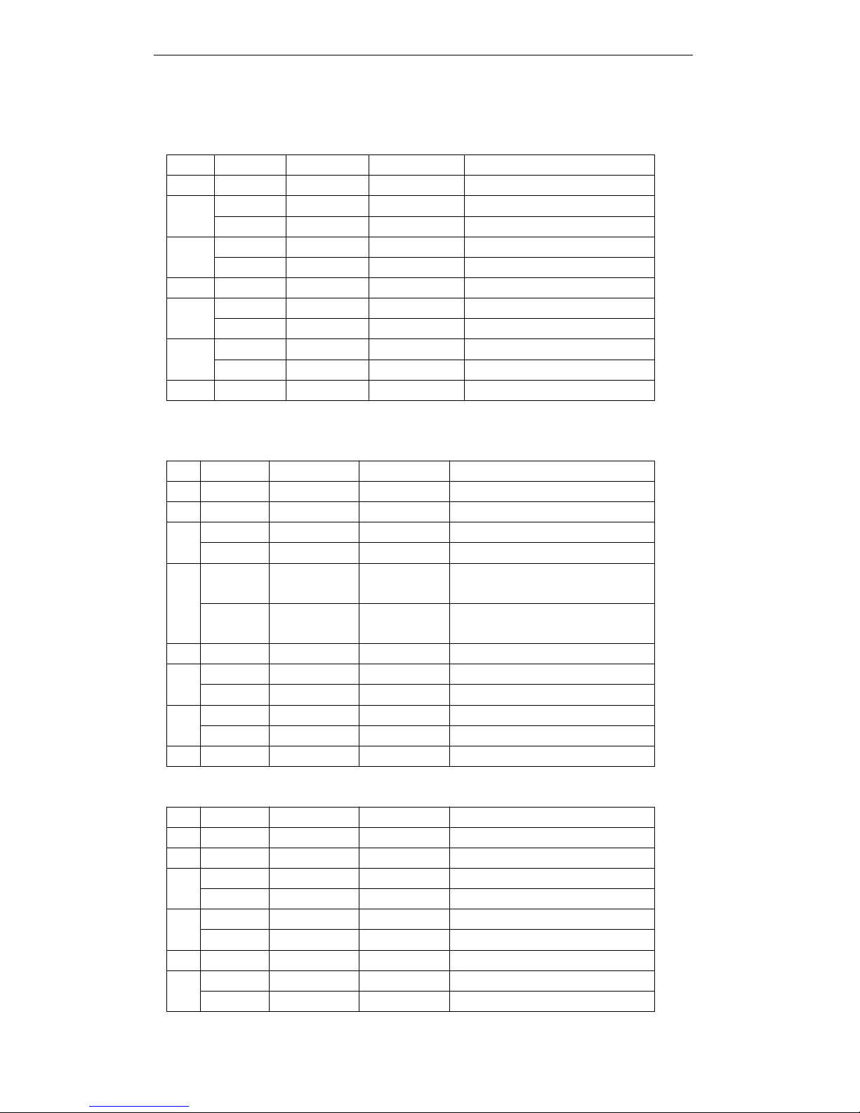
T90 User Manual
33
DSR)will be changed to MARK , so before receiving the n, interrupt DLE
DLE
DLE
DLE EOT
EOT
EOT
EOT 3
3
3
3 .
The code of DLE
DLE
DLE
DLE EOT
EOT
EOT
EOT 3
3
3
3 <10>H will be dealed with as the code of ESC
ESC
ESC
ESC 3
3
3
3 <10>H.
n = 1 Printer status
NOTE:bit 5:Online error is the process that the printer will execute waiting switch on/off during th e
macro command and self-test.
n = 2 : Offline status
Bit 5 : Turn on when stopping print when the no paper sensor detected paper end.
n = 3: Error status
Bit
Off/On
Hex
Decimal
Function
0
Off000
Not used. Select off.
12On022
Not used. Select on.
On044
Not used. Select on.
3
Off000
Online.On088Offline.
4On1016Not used. Select on.
5
Off000
Do not wait online error recovery.
On2032
Wait online error recovery.
6
Off000
Feed paper button switch off.
On4064
Feed paper button switch on.
7
Off000
Not used, Select off.
Bit
Off/On
Hex
Decimal
Function
0
Off000
Not used. Select off.
1
On022
Not used. Select on.
2
Off000
Cover is closed.
On044
Cover is open.
3
Off000
Paper is not being fed by the paper
FEED button.
On088
Paper is being fed by the paper
FEED button.
4
On1016
Not used. Select on.
5
Off000
No paper end stop.
On2032
Printing stopped by paper end.
6
Off000
No error.
On4064
Error occurred.
7
Off000
Not used. Select off.
Bit
Off/On
Hex
Decimal
Fuction
0
Off000
Not used. Select off.
1
On022
Not used. Select on.
2
Off000
No mechanical error.
On044
Mechanical error occurred.
3
Off000
No autocut error.
On088
Autocut error occurred.
4
On1016
Not used. Select on.
5
Off000
No unrecoverable error.
On2032
Unrecoverable error occurred.
Page 40
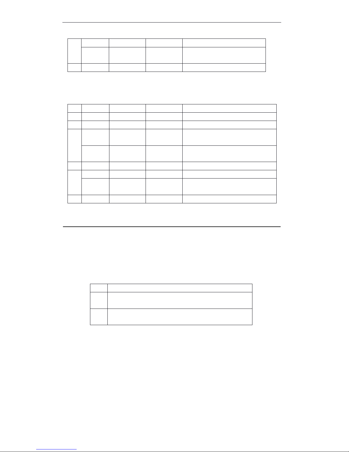
T90 User Manual
34
Bit 2 : While the cover is opening, the printer showed it as the mechanical error.
Bit 6:If the temperature of print head is extremely high, bit 6 will be turn on, until temperature of th e
print head effectively comes down or open the cover during printing.
n = 4: Roll paper sensor status
[Reference] DLE
DLE
DLE
DLE ENQ
ENQ
ENQ
ENQ , GS
GS
GS
GS a
a
a
a , GS
GS
GS
GS r
r
r
r
DLE
DLE
DLE
DLE ENQ
ENQ
ENQ
ENQ n
n
n
n
[Name] Real-time request to printer
[Format] ASCII DLE ENQ n
Hex 10 05 n
Decimal 16 5 n
[Range] 1 ≤
n ≤
2
[Description] Responds to a request in real-time from the host computer. N appoint the following
functions
[Paticularize] · This command only effected when the autocutter error, cover open.
• Deal with the data once the printer receive this command.
· Though the printer is offline, full printing buffer or serial interface mode error, always
execute this command.
· In parallel interface mode, this command can not be executed when the printer is
busy.When Memory Switch 1-3 is ON , even the printer is offline, the printer do not
set BUSY.
·
DLE
DLE
DLE
DLE ENQ
ENQ
ENQ
ENQ 2
2
2
2 allow that the printer recovers after clearing receiving buffer area and
printing area. When the printer keep the error occurred , it located in effective set ( as
ESC
ESC
ESC
ESC !
!
!
! , ESC
ESC
ESC
ESC 3
3
3
3 etc ) . Compeletly initialize the printer by this command and ESC
ESC
ESC
ESC @
@
@
@ .
.
.
.
6
Off000
No automatically recoverable error.
Off4064
Automatically recoverable error
occurred.
7
On000
Not used. Select off.
Bit
Off/On
Hex
Decimal
Function
0
Off000
Not used. Select off.
1
On022
Not used. Select on. 。
2,3
Off000
No paper end detected by paper near-
end sensor.On0C
12
Paper near-end detected by paper near-
end sensor.
4
On1016
Not used. Select on.
5,6
Off000
Paper near-end sensor : with paper.
On6096
Paper near-end detect printing to the
paper end.
7
Off000
Not used. Select off.
n
Function
1
Recovers from a recoverable error and restarts printing from the
line where the error occurred.
2
Recovers from a recoverable error after clearing the receive and
print buffers.
Page 41

T90 User Manual
35
This command only effects for the error which can be recovered, except for print head
temperature error.
[Notes] · Whenever receive <10>H<05>H<n> (1 ≤
n ≤
2) data sequence , will send status.
For example:
ESC * m nL nH dk , d1 = <10>H, d2 = <05>H, d3 = <01>H
· In the command data includes 2 or more bytes, can not use this command.
For example :
If want to send ESC
ESC
ESC
ESC 3
3
3
3 n
n
n
n to the printer, but before sending the n, DTR ( For the host
is DSR)will change to MARK
,
hence before receiving n, DLE
DLE
DLE
DLE ENQ
ENQ
ENQ
ENQ 2
2
2
2 to discontinue .
The code of DLE
DLE
DLE
DLE ENQ
ENQ
ENQ
ENQ 2
2
2
2 <10>H will be processed by the code <10>H of ESC
ESC
ESC
ESC 3
3
3
3 .
[Reference] LE
LE
LE
LE EOT
EOT
EOT
EOT
ESC
ESC
ESC
ESC FF
FF
FF
FF
[Name] Print data in page mode
[Format] ASCII ESC FF
Hex 1B 0C
Decimal 27 12
[Description] In page mode, put together to print all data in the printing buffer area.
[Particularize] This effected only in page mode.
· After printing, the printer do not clear the data which set by ESC T and ESC W and
the characters data position in the buffer area.
[Reference] FF
FF
FF
FF , ESC
ESC
ESC
ESC L
L
L
L , ESC
ESC
ESC
ESC S
S
S
S
ESC
ESC
ESC
ESC SP
SP
SP
SP n
n
n
n
[Name] Set right-side character spacing
[Format] ASCII ESC SP n
Hex 1B 20 n
Decimal 27 32 n
[Range] 0 ≤
n ≤
255
[Description] Set right-side character spacing [n ×
0.125 mm].
[Particularize] · For double width mode, right-side character spacing is the twice than the unusal
mode.When the characters enlarges to n times, right-side character spacing is
the n times than the usual mode.
· This command does not affect the setting of the Chinese characters.
· This command set righ-side character spacing in stable mode and page mode.
[Default] n = 0
ESC
ESC
ESC
ESC !
!
!
! n
n
n
n
[ Name ] Select print modes
[ Format ] ASCII ESC ! n
Hex 1B 21 n
Decimal 27 33 n
[ Range ] 0 ≤
n ≤
255
Page 42

T90 User Manual
36
[ Description ] Select print modes by the data of appointing parameter n. The definition of n as follow s:
[ Particularize ] When selecting the double height and width mode at the same time, print 4
times characters .
The printer can add the underline to all characters, but can not add the
underline to blank and clockwise switching 90 which set by HT command.
· The thickness of the underline set by ESC, unrelated with the character size.
· When the double or more height characters in one line, all characters will be
justified along basis line
·
ESC
ESC
ESC
ESC M
M
M
M could be set the font type of characters. T he last command received
that is effective.
· ESC
ESC
ESC
ESC E
E
E
E Empahsized mode is turned on/off. T he last command received that is
effective.
· ESC
ESC
ESC
ESC –
–
–
– Under mode is turned on/off, the last command received that is
effective.
· GS
GS
GS
GS !
!
!
! Set character size. The last command received that is effective.
· Emphasized mode is affect for English and Chinese characters. All print mode
only affect for English expect for emphasized mode.
[ Default ] n = 0
[ Reference ] ESC
ESC
ESC
ESC -
-
-
- , ESC
ESC
ESC
ESC E
E
E
E , GS
GS
GS
GS !
!
!
!
ESC
ESC
ESC
ESC $
$
$
$ nL
nL
nL
nL nH
nH
nH
nH
[Name] Set absolute print position
[Format] ASCII ESC $ nL nH
Hex 1B 24 nL nH
Decimal 27 36 nL nH
[Range] 0 ≤
nL ≤
255
0 ≤ nH ≤
255
[Description] Set the distance from the beginning of one line to the position which will be printed the
characters.
The distance from the beginning of one line to the position which will be printed is:
[(nL + nH ×
256) × 0.125 mm ] 。
BitOff/On
Hex
Decimal
Function
0
Off000
Character type A (12 ×
24) 。
On011
Character type B (9 ×
17) 。
1
---
Undefined2---
Undefined3Off0Emphasized mode is turned off.
On8Enphasized mode is turned on.
4
Off0Double height canceled
On16Double height selected
5
Off0Double width canceled
On32Double width selected
6
----
Undefined
7
Off0Underline mode is turned off
On
128
Underline mode is turned on
Page 43

T90 User Manual
37
[Particularize] · The set which be appointed as the print area will be ignored.
·
In stable mode, use the horizontal motor unit (x) .
· In page mode, horizontal or vertical motor unit wihich will be different as the original of
printable area, as follows:
① When ESC
ESC
ESC
ESC T
T
T
T set the original position to the up left or lower right printable
area,using the horizontal motor unit (x).
② When ESC
ESC
ESC
ESC T
T
T
T set the original position to the up right or lower left printablearea,using
the vertical motor unit (y).
[Reference] ESC
ESC
ESC
ESC \
\
\
\ , GS
GS
GS
GS $
$
$
$ , GS
GS
GS
GS \
\
\
\
ESC
ESC
ESC
ESC %
%
%
% n
n
n
n
[Name] Select/cancel user-defined character set
[Format] ASCII ESC % n
Hex 1B 25 n
Decimal 27 37 n
[Range] 0 ≤
n ≤
255
[Description] Select/cancel user-defined character set.
· When the LSB of n is 0, the user-defined character set is canceled.
· When the LSB of n is 1, the user-defined character set is selected.
[Particularize] · When select cancel user-defined character set, automatically select inner character
set.
· n only valid at least significant bit.
[Default] n = 0
[Reference] ESC
ESC
ESC
ESC &
&
&
& , ESC
ESC
ESC
ESC ?
?
?
?
ESC
ESC
ESC
ESC &
&
&
& y
y
y
y c1
c1
c1
c1 c2
c2
c2
c2 [x1
[x1
[x1
[x1 d1...d(y
d1...d(y
d1...d(y
d1...d(y ×
×
×
× x1)]...[xk
x1)]...[xk
x1)]...[xk
x1)]...[xk d1...d(y
d1...d(y
d1...d(y
d1...d(y ×
×
×
× xk)]
xk)]
xk)]
xk)]
[Name] Define user-defined characters
[Format] ASCII ESC & y c1 c2 [x1 d1...d(y × x1)]...[xk d1...d(y × xk)]
Hex 1B 26 y c1 c2 [x1 d1...d(y × x1)]...[xk d1...d(y × xk)]
Decimal 27 38 y c1 c2 [x1 d1...d(y × x1)]...[xk d1...d(y × xk)]
[Range] y = 3
32 ≤ c1 ≤ c2 ≤ 126
0 ≤
x ≤
12 (when font A (12 ×
24) is selected)
0 ≤
x ≤
9 (when font B (9 ×
17) is selected)
0 ≤
d1...d(y × xk) ≤ 255
[Description] Define user-defined characters.
· y specifies the number of bytes in the vertical direction.
· c1 specifies the beginning character code for the definition, and c2 specifiesthefinal
code.
· x specifies the number of dots in the horizontal direction.
[Particularize] · Characters code can be defined: ASCII from <20>H to <7E>H (95 characters ) .
· The continued characters code of several characters can be undefined. When only
need one character, so c1 = c2
。
· d is the dot data of characters. D ot mode is from the left in horizontal direction. T he
right left dots are blank.
· Define the data of user-defined character is (y × x) bytes.
Page 44
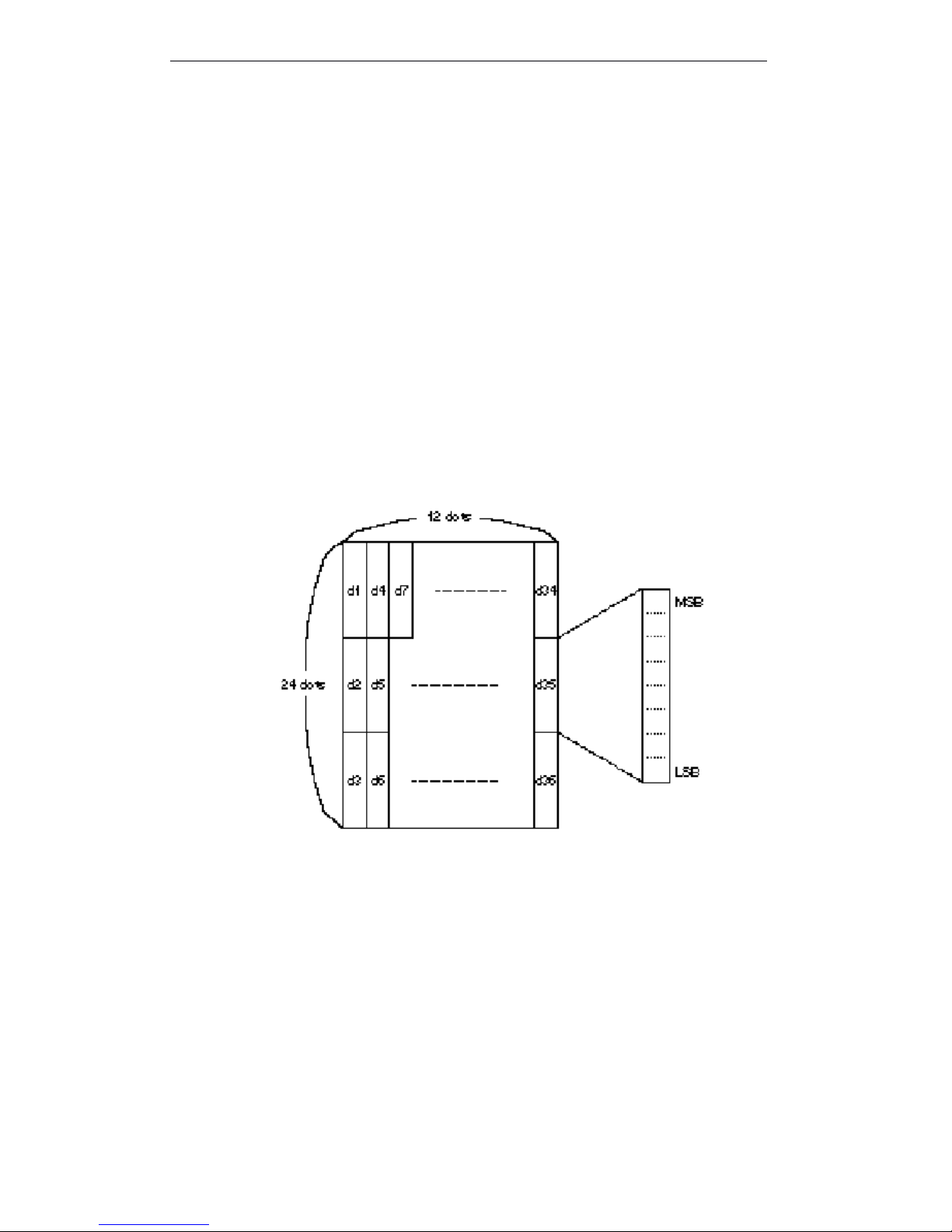
T90 User Manual
38
· Set the relevant of printing dot is 1 or 0 which is the relevant of do not printing the
dots.
· Define the different user-defined character mode for each character type by this
command. Set the character type by ESC
ESC
ESC
ESC !
!
!
! or ESC
ESC
ESC
ESC M
M
M
M .
· User -defined character and download bit image can not define at the same time.
Whenexecuting this command, download bit image will be cleared.
· Under the following situations, user-defined characters will be cleared:
① Execute ESC
ESC
ESC
ESC @
@
@
@ .
② Execute GS
GS
GS
GS *
*
*
* .
③ Execute ESC
ESC
ESC
ESC ?
?
?
? .
④ The printer reset or turn the power off.
· When the user-defined characters defines in character type B (9 ´ 17) , only effect
to the highest valiable bit of the third byte in the vertical direction data.
[ Default ] Inner character font
[ Reference ] ESC
ESC
ESC
ESC %
%
%
% , ESC
ESC
ESC
ESC ?
?
?
?
[ For example ]
· When setting the character type A (12 ×
24) .
Page 45
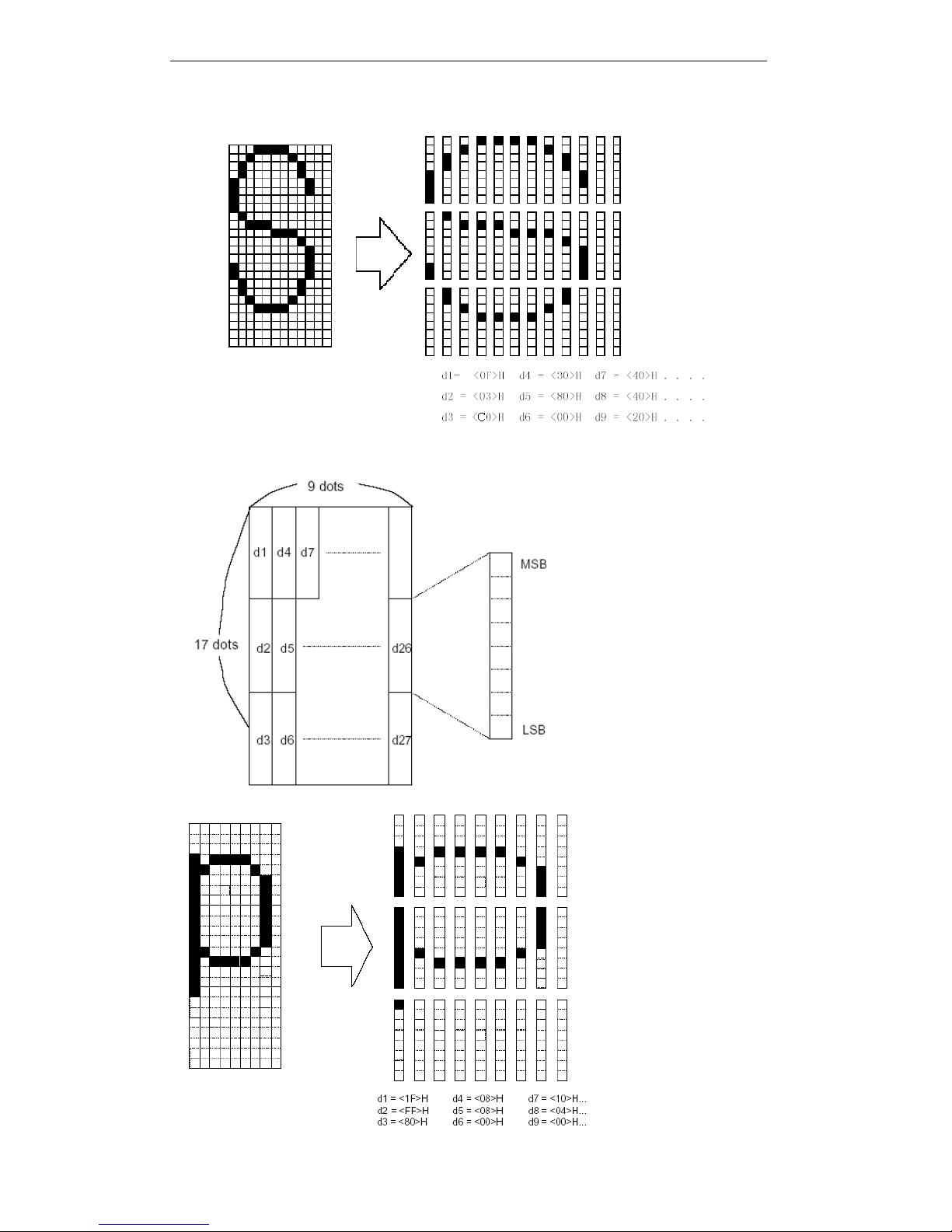
T90 User Manual
39
· When set the character type B (9 × 17).
Page 46

T90 User Manual
40
ESC
ESC
ESC
ESC *
*
*
* m
m
m
m nL
nL
nL
nL nH
nH
nH
nH d1...
d1...
d1...
d1... dk
dk
dk
dk
[Name] Select bit-image mode
[Format] ASCII ESC *
m nL nH d1...dk
Hex 1B 2A m nL nH d1...dk
Decimal 27 42 m nL nH d1...dk
[Range] m = 0, 1, 32, 33
0 ≤ nL ≤ 255
0 ≤ nH
≤ 3
0 ≤
d ≤
255
[Description] Selects bit-image mode by m, the bit image dot set by nL and nH, as above table:
Dpi: {1 inch}/25.4mm print dot
[ Notes ] If the data of m overs the defined range, then the data of n and after n will be dealt
as the rule data.
· nL and nH indicates the bit-image data in the horizontal direction. Calculate the dot
through nL + nH ×
256 .
· If input the bit-image data that overs the printable dots in one line, then the over
data will be ignored.
· d indicates bit-image data. Set the relative bit to 1 and print one point, or set to 0
and do not print one point.
· If the printable width which set by GS
GS
GS
GS L
L
L
L and GS
GS
GS
GS W
W
W
W is smaller than the data which
sent by ESC * , Then executing the following operation to the line which have
problems (but the printing can not over the max printable area):
① The printable width extend to the right and meet the data content.
② If the step ① can not apply the enough width to the data, so the left will be
decreased to apply the relative data. For the bit data in the single density mode
(m = 0, 32) , The printer has two points: for the bit dat in the double density
mode (m = 1, 33) , the printer prints one point. When calculating the data
content in one line, these have to consider.
· After printing one bit-image, the printer return to the common data dealing mode.
· This command won ’ t be affected by printing mode( bold 、 overlapping 、 underline 、
character size 、 or inverse printing ) , except for upside down print mode.
· The following figures describes the the relationship of image data and printing dot .
· 8- dot bit-image is selected:
m
Mode
Vertical direction
Horizontal direction
Dot
Dot density
Dot density
Data number (K)
0
8-dot single-
density
8
67.7 dpi
101.6 dpi
nL + nH ×
256
1
8-dot double-
density
8
67.7 dpi
203.2 dpi
nL + nH × 256
3224-dot single-
density
24
203.2 dpi
101.6 dpi
(nL + nH ×
256)
× 3
3324-dot double-
density
24
203.2 dpi
203.2 dpi
(nL + nH ×
256)
× 3
Page 47
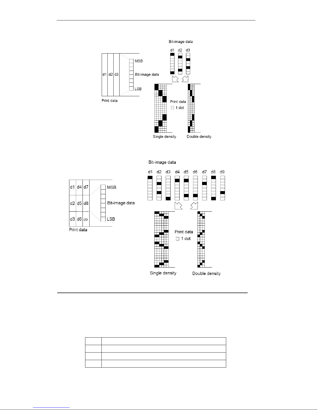
T90 User Manual
41
• 24- dot bit-image is selected:
ESC
ESC
ESC
ESC –
–
–
– n
n
n
n
[Name] Turn underline mode on/off
[Format] ASCII ESC - n
Hex 1B 2D n
Decimal 27 45 n
[Range] 0 ≤
n ≤
2, 48 ≤
n ≤
50
[Description] Turns underline mode on/off:
n
Function
0, 48
Turns off underline mode.
1, 49
Turns on underline mode (1 dot width )
2, 50
Turns on underline mode (2 dot width )
Page 48

T90 User Manual
42
[Notes] · The printer can print all character with underline (include the right spacing of
character), except for blank which set by HT.
· The printer can not print underline of the character of clockwise 90 and reverse
character.
· Turns off underline mode by setting the data of n with 0 or 48, the following data
won ’ t print underline, and the bold won ’ t change before turing off underline mode.
T he bold of default underline is 1 dot.
· Changes the character size won ’ t affect the bold of underline.
· Turned on/off underline mode by ESC !. but notes that the last receiving command
is valid.
[Default] n = 0
[ Reference ] ESC !
ESC
ESC
ESC
ESC 2
2
2
2
[ Name ] Select default line spacing
[ Format ] ASCII ESC 2
Hex 1B 32
Decimal 27 50
[ Description ] Sets the line spacing to 3.75 mm (30 ´ 0.125 mm ) .
[ Note ] Line spacing set independently in stable mode and page mode.
[ Reference ] ESC
ESC
ESC
ESC 3
3
3
3
ESC
ESC
ESC
ESC 3
3
3
3 n
n
n
n
[Name] Set line spacing
[Format] ASCII ESC 3 n
Hex 1B 33 n
Decimal 27 51 n
[ Range ] 0 ≤
n ≤
255
[ Description ] Set line spacing [n ×
0.125 mm ].
[Notes] Sets line spacing independently in stable mode and page mode.
· In stable mode, uses vertical unit (y) .
· In page mode, as the printable original position , the function of this command as
followings:
① When set the original position to printable up left or down right by ESC T, uses
vertical motor unit (y) .
② When set the original position to printable up right or down left by ESC T, used
the horizontal motor unit (x) .
[ Default ] n = 30
[ Reference ] ESC
ESC
ESC
ESC 2
2
2
2
ESC
ESC
ESC
ESC ?
?
?
? n
n
n
n
[ Name ] Cancel user-defind characters
[ Format ] ASCII ESC ? n
Hex 1B 3F n
Decimal 27 63 n
Page 49

T90 User Manual
43
[ Range ] 32 ≤
n ≤ 126
[ Description ] Cancel user-defined characters.
[ Notes ] · This command stops the type which defined for character code, character code set
by n
. After canceling the user-defiend character, prints with inner character relative mode .
· Select character type by ESC !, this command delects the type which defined the
pointed code.
· If one of the user-defined characters do not define, then the printer ignore this
command.
[ Reference ] ESC
ESC
ESC
ESC &
&
&
& , ESC
ESC
ESC
ESC %
%
%
%
ESC
ESC
ESC
ESC @
@
@
@
[ Name ] Initialize printer
[ Format ] ASCII ESC @
Hex 1B 40
Decimal 27 64
[ Description ] Clears the data in the print buffer and resets the printer modes to the modes that were
in effect when the power was turned on.
[ Notes ] · The set of DIP swith and Memory Switch won ’ t check.
· The data in receiving buffer area won ’ t be cleared.
· Macro definition won ’ t be cleared.
ESC
ESC
ESC
ESC D
D
D
D n1
n1
n1
n1 .
.
.
. .
.
.
. .
.
.
. nk
nk
nk
nk NUL
NUL
NUL
NUL
[ Name ] Set horizontal tab positions
[ Format ] ASCII ESC D n1 . . . nk NUL
Hex 1B 44 n1 . . . nk 00
Decimal 27 68 n1 . . . nk 0
[ Range ] 1 ≤
n ≤
255
0 ≤
k ≤
32
[ Description ] Set horizontal tab positions.
· n specifies the number from the beginning of one line, uses to set horizontal
position.
· k indicates the total data which set by horizontal position.
[ Notes ] · Horizontal position as a data to store, this data is [ character width ´ n] , is
measuring from the beginning of the line. The character width includes the right
spacing of the character, and double width character set by double width of stable
character.
· This command delects the horizontal position which set before.
· When set n = 8, the print position moved to the ninth row by sending HT.
· Could be set position to 32 (k = 32) . T he data overs 32 will be dealt as normal data.
· As sort ascending to transmit [n] k and put one NUL 0 at last
.
When [n] k is less than or equal to the fore data, sets position which be finished,
and the continued data dealt as normal data.
·
ESC
ESC
ESC
ESC D
D
D
D NUL
NUL
NUL
NUL cancel all horizontal position.
· Even if changes the character width, the fore specified horizontal position also do
not change.
Page 50

T90 User Manual
44
· For stable and page mode, character width will be memoried.
[ Default ] Default position is 8 character spacing ( raw 9 , 17 , 25 ...) of type A (12 ´ 24) .
[ Reference ] HT
HT
HT
HT
ESC
ESC
ESC
ESC E
E
E
E n
n
n
n
[Name] Turn emphasized mode on/off
[Format] ASCII ESC E n
Hex 1B 5 n
Decimal 27 69 n
[Range] 0 ≤
n ≤
255
[Description] Turn emphasized mode on/off.
When the LSB of n is 0, emphasized mode is turned off.
When the LSB of n is 1, emphasized mode is turned on.
[Notes] · Permits to only the LSB of n.
· This command turns emphasized mode on/off by the same command as ESC ! Be
care, when this command used the same time as ESC !.
[Default] n = 0
[Reference] ESC
ESC
ESC
ESC !
!
!
!
ESC
ESC
ESC
ESC G
G
G
G n
n
n
n
[ Name ] Turn double-strike mode on/off
[ Format ] ASCII ESC G n
Hex 1B 47 n
Decimal 27 71 n
[ Range ] 0 ≤ n ≤ 255
[ Description ] Turn double-strike mode on/off.
· When the LSB of n is 0, double-strike mode is turned off.
· When the LSB of n is 1, double-strike mode is turned on.
[ Notes ] · Permits to use only the LSB of n.
· The same output in double-strike mode and emphasized mode.
[ Default ] n = 0
[ Reference ] ESC
ESC
ESC
ESC E
E
E
E
ESC
ESC
ESC
ESC i
i
i
i
[ Name ] Full cut
[ Format ] ASCII ESC i
Hex 1B 69
Decimal 27 105
[ Description ] After receiving this command, the printer executes full cut.
[ Note ] As it won ’ t feed paper when executing this command, please assures that feed
paper5mm or more before executing this command next time, to avoid that the cutter
be damaged.
[ Default ] The default is partial cut mode.
Page 51

T90 User Manual
45
ESC
ESC
ESC
ESC J
J
J
J n
n
n
n
[ Name ] Print and feed paper
[ Format ] ASCII ESC J n
Hex 1B 4A n
Decimal 27 74 n
[ Range ] 0 ≤
n ≤
255
[ Description ] Prints and outputs the data in print buffer area, and feed paper [n ×
0.125 mm ].
[ Notes ] · After printing, this command set the original position to the beginning of one line.
· The feed paper quatinty do not affect the data which set by ESC 2 or ESC 3.
· In stable mode, the printer uses vertical unit (y) .
· In page mode, according to the printable original position, the function of this
command as follows:
① When set original position to printable up left or down right by ESC T, uses
vertical motor unit (y) .
② When set original position to printable up right or down left by ESC T, uses
horizontal motor unit (x) .
ESC
ESC
ESC
ESC L
L
L
L
[ Name ] Select page mode
[ Format ] ASCII ESC L
Hex 1B 4C
Decimal 27 76
[ Description ] From stable mode to page mode.
[ Notes ] · In stable mode, this command affects only the beginning of one line.
· This command is invalidate in page mode.
· Finishes the printing by FF or executes ESC S, the printer returns to the stable
mode.
· This command set the position of data buffer area which be set by ESC T in
printable area. Printable range defines by ESC W.
· This command set the following commands ( In these commands, the data of stable
mode and page mode could be set separately ) as the relevant set in page mode.
① Set the right characters spacing : ESC
ESC
ESC
ESC SP
SP
SP
SP
② Select default line spacing : ESC
ESC
ESC
ESC 2
2
2
2 ,
,
,
, ESC
ESC
ESC
ESC 3
3
3
3
· In page mode, only can set the following command data; but do not execute these
commands.
① Set/cancel clockwise 90 ° Rotate : ESC
ESC
ESC
ESC V
V
V
V
② Select alignment : ESC
ESC
ESC
ESC a
a
a
a
③ Set/cancel reverse print mode : ESC
ESC
ESC
ESC {
{
{
{
④ Set left page spacing : GS
GS
GS
GS L
L
L
L
⑤ Set print area width : GS
GS
GS
GS W
W
W
W
· Turn the power on, printing reset or uses ESC @ , The printer return to stable mode.
[ Reference ] FF
FF
FF
FF , CAN
CAN
CAN
CAN ,
,
,
, ESC
ESC
ESC
ESC FF
FF
FF
FF , ESC
ESC
ESC
ESC S
S
S
S , ESC
ESC
ESC
ESC T
T
T
T , ESC
ESC
ESC
ESC W
W
W
W , GS
GS
GS
GS $
$
$
$ , GS
GS
GS
GS \
\
\
\
ESC
ESC
ESC
ESC m
m
m
m
[Name] Partial cut
Page 52
T90 User Manual
46
[Format] ASCII ESC m
Hex 1B 6d
Decimal 27 109
[Description] The printer received this command, then executing partial cut at present position.
[Note] As the printer do not feed paper when executing this command, so before executing
this command in the next time, assure that feed paper at least 5mm or more, prevent
cu tter broken.
[Default] Partial cut mode is default.
ESC
ESC
ESC
ESC M
M
M
M n
n
n
n
[ Name ] Select character font
[ Format ] ASCII ESC M n
Hex 1B 4D n
Decimal 27 77 n
[ Range ] n = 0, 1, 48, 49
[ Description ] Select character font
[ Particularize ] · ESC
ESC
ESC
ESC !
!
!
! could be selected character type. But, the set by command received at last is
valid.
[ Reference ] ESC
ESC
ESC
ESC !
!
!
!
ESC
ESC
ESC
ESC R
R
R
R n
n
n
n
[ Name ] Select an international character set
[ Format ] ASCII ESC R n
Hex 1B 52 n
Decimal 27 82 n
[ Range ] 0 £ n £ 13
[ Description ] Select an international character set according to the following table.
n
Function
0, 48
Select character font A (12 ×
24)
1, 49
Select character font B (9 ×
17)
n
International character set
0
USA
1
France
2
Germany
3UK4
Denmark I
5
Sweden6Italy
7
Spain I8Japan
9
Norway
1
0
Denmark II
1
Spain II
Page 53
T90 User Manual
47
[ Default ] n = 0
[ Reference ] International character set
ESC
ESC
ESC
ESC S
S
S
S
[ Name ] Select standard mode
[ Format ] ASCII ESC S
Hex 1B 53
Decimal 27 83
[ Description ] Switch from page mode to standard mode.
[ Notes ] · This command only effects in page mode.
· In page mode Clear the data in buffer area.
· This command set the original of the line as the print position.
· The print area set by ESC W which be initialized.
· This command set the following commands ( In these commands, the data of stable
mode and page mode could be set separately ) as the relevant set in stable mode:
① Set right side character spacing : ESC
ESC
ESC
ESC SP
SP
SP
SP
② Select default line spacing : ESC
ESC
ESC
ESC 2
2
2
2 , ESC
ESC
ESC
ESC 3
3
3
3
[ Reference ] FF
FF
FF
FF , ESC
ESC
ESC
ESC FF
FF
FF
FF , ESC
ESC
ESC
ESC L
L
L
L
ESC
ESC
ESC
ESC T
T
T
T n
n
n
n
[ Name ] Select print direction in page mode
[ Format ] ASCII ESC T n
Hex 1B 54 n
Decimal 27 84 n
[ Range ] 0 ≤
n ≤
3
48 ≤
n ≤
51
[ Description ] In page mode, selects the print direction and starting position.
Parameter n which used to be pointed print direction
and starting position, as follows:
[ Notes ] · Input this command in stable mode, the printer only executes inner signs operation. This
command can not be affected print in stable mode.
· This command in print area which set by ESC W, set the data buffer position.
[ Default ] n = 0
112
Latin America
1
3
Korea
n
Print direction
Starting position
0,4 8
Left to right
Upper left ( Figure A
)
1,4 9
Bottom to top
Lower left ( Figure B
)
2,5 0
Right to left
Lower right ( Figure C
)
3,5 1
Top to bottom
Upper right ( Figure D
)
Page 54

T90 User Manual
48
[ Reference ] ESC
ESC
ESC
ESC $
$
$
$ , ESC
ESC
ESC
ESC L
L
L
L , ESC
ESC
ESC
ESC W
W
W
W , ESC
ESC
ESC
ESC \
\
\
\ , GS
GS
GS
GS $
$
$
$ , GS
GS
GS
GS \
\
\
\
ESC
ESC
ESC
ESC V
V
V
V n
n
n
n
[ Name ] Turn 90 clockwise rotation mode on/off
[ Format ] ASCII ESC V n
Hex 1B 56 n
Decimal 27 86 n
[ Range ] 0 ≤
n ≤
1, 48 ≤ n ≤ 49
[ Description ] Turn 90 clockwise rotation mode on/off
[ Notes ] · This command effects print in stable mode. A nd the set always effects.
· When setting the underline mode, for 90 clockwise rotation character, the printer do
not be add the underline. °
· In 90 clockwise rotation mode, the direction of enlarging characters which set by
double height and width is relative with the direction in general mode.
[ Default ] n = 0
[ Reference ] ESC
ESC
ESC
ESC !
!
!
! , ESC
ESC
ESC
ESC -
-
-
-
ESC
ESC
ESC
ESC W
W
W
W xL
xL
xL
xL xH
xH
xH
xH yL
yL
yL
yL yH
yH
yH
yH dxL
dxL
dxL
dxL dxH
dxH
dxH
dxH dyL
dyL
dyL
dyL dyH
dyH
dyH
dyH
[ Name ] Set print area in page mode
[ Format ] ASCII ESC W xL xH yL yH dxL dxH dyL dyH
Hex 1B 57 xL xH yL yH dxL dxH dyL dyH
Decimal 27 87 xL xH yL yH dxL dxH dyL dyH
[ Range ] 0 ≤ xL,xH,yL,yH,dxL,dxH,dyL,dyH ≤
255 ( except dxL = dxH =0 or dyL = dyH =0)
[ Description ] · x0, y0, dx, dy specify the horizontal and vertical starting position, print area width
and height separately.
Each item setting data in print area as follows:
x0 = [( xL + xH ×
256)
×
0.125 mm]
y0 = [( yL + yH ×
256)
×
0.125 mm]
dx = [( dxL + dxH × 256)
×
0.125 mm]
dy = [( dyL + dyH × 256)
×
0.125 mm]
[ Notes ] · If input this command in stable mode, the printer only executes inner sign operation .
This command can not be affected print in stable mode.
· If the set of horizontal and vertical starting position overs printable area, printer
stops command processing and deal with the continued data as normal data.
· If the set of print area width and height is 0, printer stops command processing and
deal with the continued data as normal data.
· This command set the data buffer area the same as the position which set by ESC
T in the print area.
· If ( horizontal starting position + print area width ) overs printable area, print area
width set automatically ( horizontal printable area – horizontal starting position ) .
· If ( vertical starting position + print area height ) overs printable area, print area
height set automatically ( vertical printable area – vertical starting position ) .
N
Fuction
0, 48
Turn off 90 clockwise rotation mode
1, 49
Turn on 90 clockwise rotation mode
Page 55
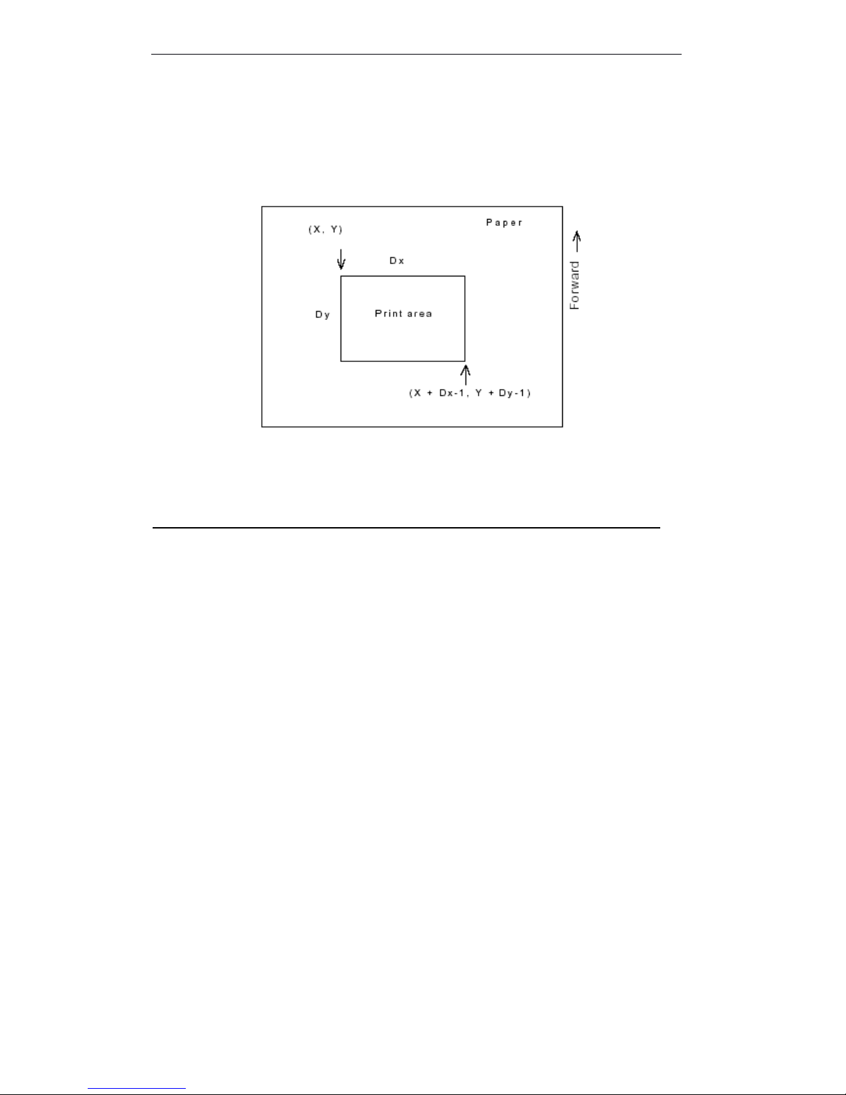
T90 User Manual
49
· Set horizontal starting position and print area width by using 0.125mm spacing, and
set vertical starting position and print area height.
· x0, y0, dx and dy specify horizontal starting horizontal starting position, vertical
starting position, print area width, print area height separately, print area set as
follows:
[ Default ] xL = xH = yL = yH = 0
[ Reference ] CAN
CAN
CAN
CAN , ESC
ESC
ESC
ESC L
L
L
L , ESC
ESC
ESC
ESC T
T
T
T
ESC
ESC
ESC
ESC \
\
\
\ nL
nL
nL
nL nH
nH
nH
nH
[ Name ] Set relative print position
[ Format ] ASCII ESC \ nL nH
Hex 1B 5C nL nH
Decimal 27 92 nL nH
[ Range ] 0 ≤ nL ≤
255
0 ≤ nH ≤
255
[ Description ] On basis of present position, set print starting position by horizontal and vertical motor
unit.
· This command set the print position from present position to [(nL + nH ×
256) ×
0.125 mm ] 。
[ Notes ] · Any set over printable area which will be ignored.
· Spacing N points the right:
nL + nH ×
256 = N
Spacing
N point the left
: ( negative direction ), uses 65536 complement code .
nL + nH ×
256 = 65536 × N
· In stable mode, uses horizontal motor unit.
· In page mode, according to the different of print area staring position, the difference
of horizontal motor unit and vertical motor unit as follows:
① Set the starting position upper left or lower right by ESC T, uses horizontal motor
unit (x ).
② Set the starting position upper right or lower left by ESC T, uses vertical motor
unit (y) .
[Reference] ESC
ESC
ESC
ESC $
$
$
$
Page 56
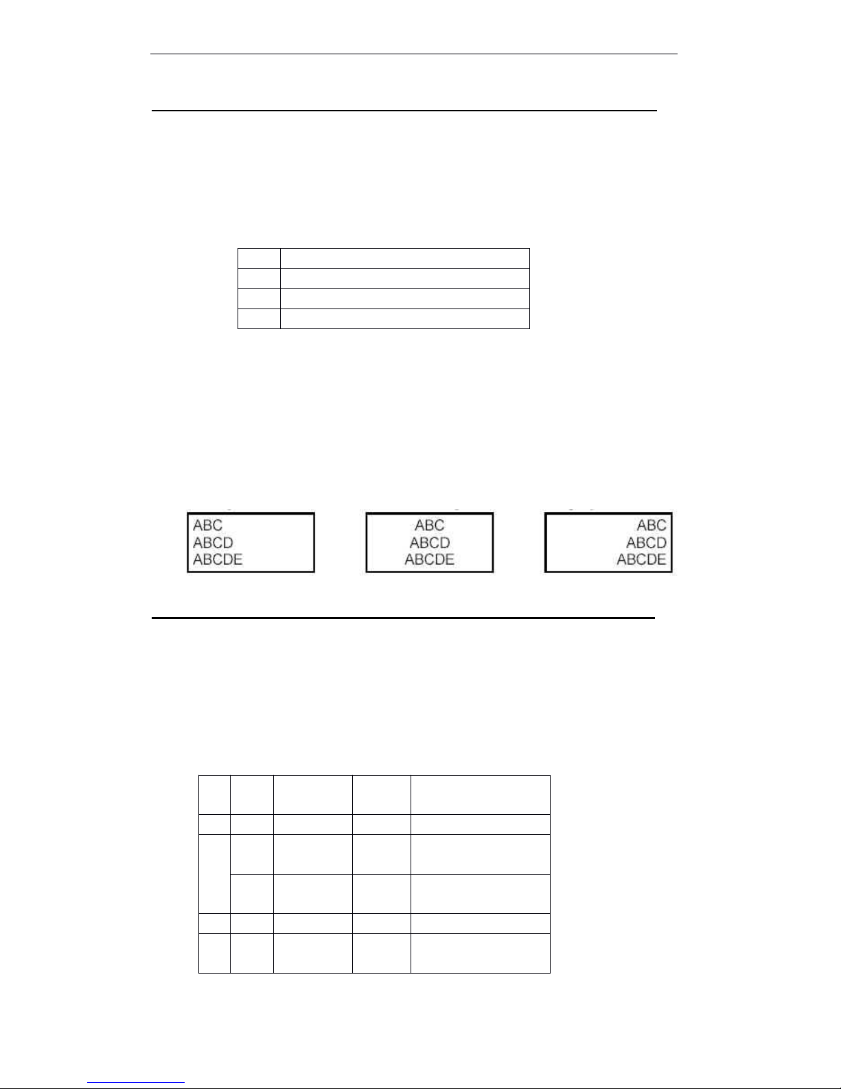
T90 User Manual
50
ESC
ESC
ESC
ESC a
a
a
a n
n
n
n
[Name] Select justification
[Format] ASCII ESC a n
Hex 1B 61 n
Decimal 27 97 n
[Range] 0 ≤
n ≤
2, 48 ≤
n ≤ 50
[Description] Justify a line data according to the point position
Select justification by n as follows:
[Notes] · In stable mode, this command is valid only the original line.
· If input this command in page mode, printer only executes inner sign operation.
This command invalids in page mode.
· This command executes justification in print area.
· This command justifys the blank area according to HT
HT
HT
HT , ESC
ESC
ESC
ESC $
$
$
$ or ESC
ESC
ESC
ESC \
\
\
\ .
[Default] n = 0
[Examples]
Left
Left
Left
Left justification
justification
justification
justification Centering
Centering
Centering
Centering Right
Right
Right
Right
justification
justification
justification
justification
ESC
ESC
ESC
ESC c
c
c
c 3
3
3
3 n
n
n
n
[ Name ] Select paper sensors to output paper-end signals
[ Format ] ASCII ESC c 3 n
Hex 1B 63 33 n
Decimal 27 99 51 n
[ Range ] 0 ≤ n ≤ 255
[ Description ] Select paper sensors to output paper-end signals .
· Uses each parameter n as follows:
n
Justification
0, 48
Left justification
1, 49
Centering
2, 50
Right justification
Bit
Off / O
n
Hex
Decimal
Function
0
Off--
Undefined .
1
Off000
Roll paper near-end
sensor disable.
On022
Roll paper near-end
sensor enable.
2
Off--
Undefined .
3
Off000
Roll paper end sensor
disable.
Page 57
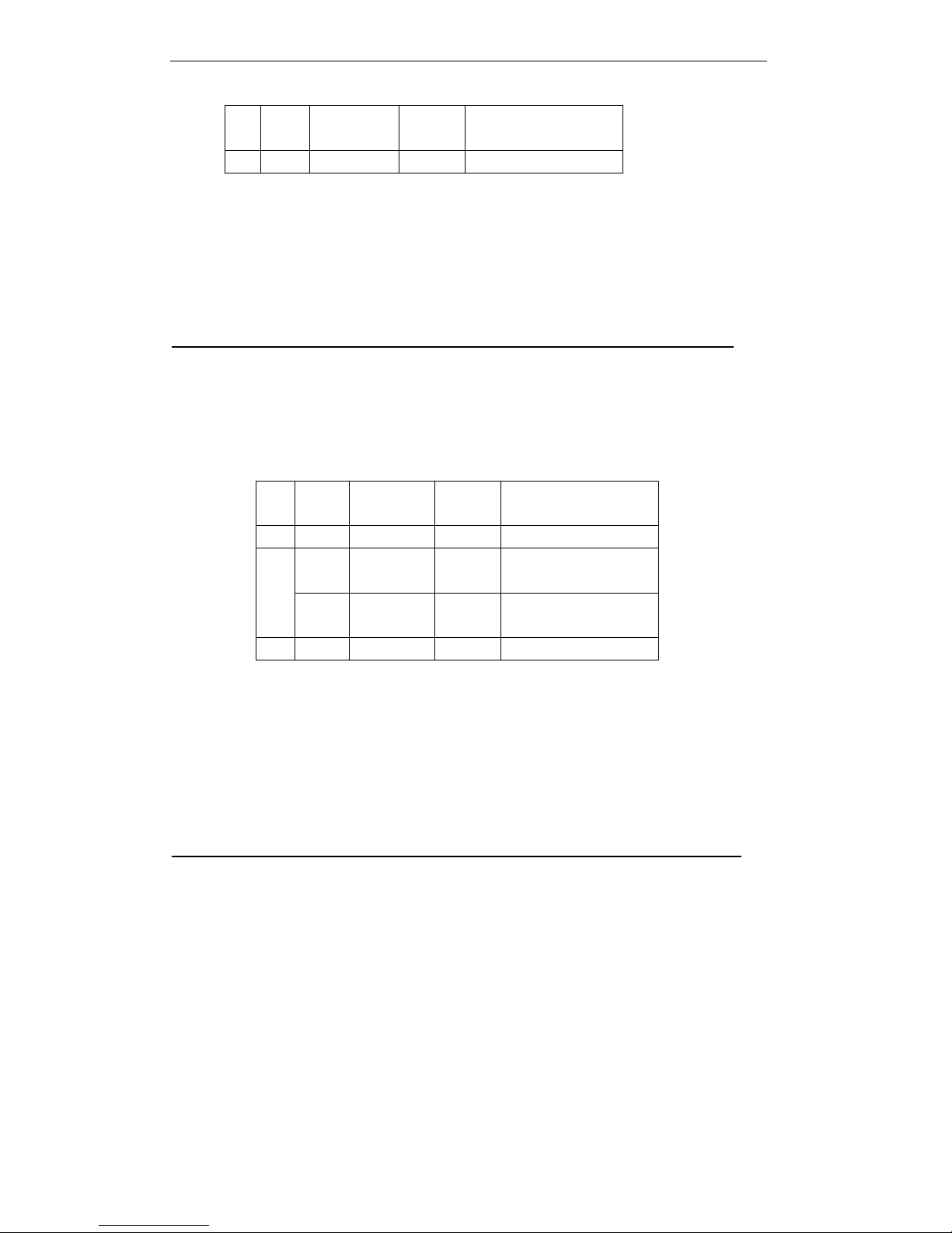
T90 User Manual
51
[ Notes ] · Select several sensors and input signal. In this case, if any one of sensors detect
paper out, it will output paper out signal.
· This command only effects to parallel interface, in serial interface mode, this
command will be ignored.
[ Default ] n = 0
ESC
ESC
ESC
ESC c
c
c
c 4
4
4
4 n
n
n
n
[ Name ] Select paper sensors to stop printing
[ Format ] ASCII ESC c 4 n
Hex 1B 63 34 n
Decimal 27 99 52 n
[ Range ] 0 ≤ n ≤ 255
[ Description ] Selects the paper sensor to stop printing when paper end detected.
[ Notes ] When this command enables one roll paper sensor, only uses the related roll paper,
the printer will be stopped.
· When paper end sensor detects the end of paper, the printer stops printing and
enters to offline condition.
· When bit 1 is on, the printer selects paper near end sensor and stops printing.
[ Default ] n = 0
ESC
ESC
ESC
ESC c
c
c
c 5
5
5
5 n
n
n
n
[ Name ] Enable/disable panel buttons
[ Format ] ASCII ESC c 5 n
Hex 1B 63 35 n
Decimal 27 99 53 n
[ Range ] 0 ≤ n ≤ 255
[ Description ] Enable/disable panel buttons.
· When the LSB of n is 0, the panel buttons are enabled.
· When the LSB of n is 1, the panel buttons are disabled.
[ Notes ] · Only uses the LSB of n.
· If disable the panel buttons, so close the printer cover, all buttons are disable.
· For this printer, the only one panel button is feed paper button.
· When locates in macro executing conditions, however how to set this command,
On088
Roll paer end sensor
enable.
4-7---Undefind.
Bit
Off / OnHex
Decimal
Fuction
0
Off--
Undefinded.
1On00
0
Roll paper near end
sensor disabled.
Off022
Roll paper near end
sensor enabled.
2-7---Undefined.
Page 58

T90 User Manual
52
feed paper button are enable. B ut can not feed paper.
[ Default ] n = 0
ESC
ESC
ESC
ESC d
d
d
d n
n
n
n
[ Name ] Print and feed n lines
[ Format ] ASCII ESC d n
Hex 1B 64 n
Decimal 27 100 n
[ Range ] 0 ≤
n ≤
255
[ Description ] Prints the data in the right buffer and feeds the paper n.
[ Notes ] · This command set the print starting position to line starting position.
· This command can not effect the line spacing which set by ESC 2 or ESC 3.
· The max feed paper measure is 1016 mm {40 inch } . If the specified feed paper
measure (n line spacing) overs 1016mm{40inch}, so the printer only feed paper
1016mm{40 inch}.
[ Reference ] ESC
ESC
ESC
ESC 2
2
2
2 , ESC
ESC
ESC
ESC 3
3
3
3
ESC
ESC
ESC
ESC t
t
t
t n
n
n
n
[ Name ] Select character code table
[ Format ] ASCII ESC t n
Hex 1B 74 n
Decimal 27 116 n
[ Range ] 0 ≤ n ≤
5, 16 ≤ n
≤
19, n = 255
[ Decription ] Select page n from the character code table.
[ Default ] n = 0
[ Reference ] Character tables
ESC
ESC
ESC
ESC {
{
{
{ n
n
n
n
[ Name ] Turn upside-down print mode on/off
[ Format ] ASCII ESC { n
Hex 1B 7B n
Decimal 27 123 n
n
Page
0
PC437 [ USA Standard Europe ]
1
Katakana
2
PC850 [ Multilingual ]
3
PC860 [ Poruguese ]
4
PC863 [ Canadian - French ]
5
PC865 [ Nordic ]
16
WPC1252
17
PC866 [ Cyrillic 2]
18
PC852 [ Latin 2]
19
PC858 [ Euro ]
25
5
Space page
Page 59
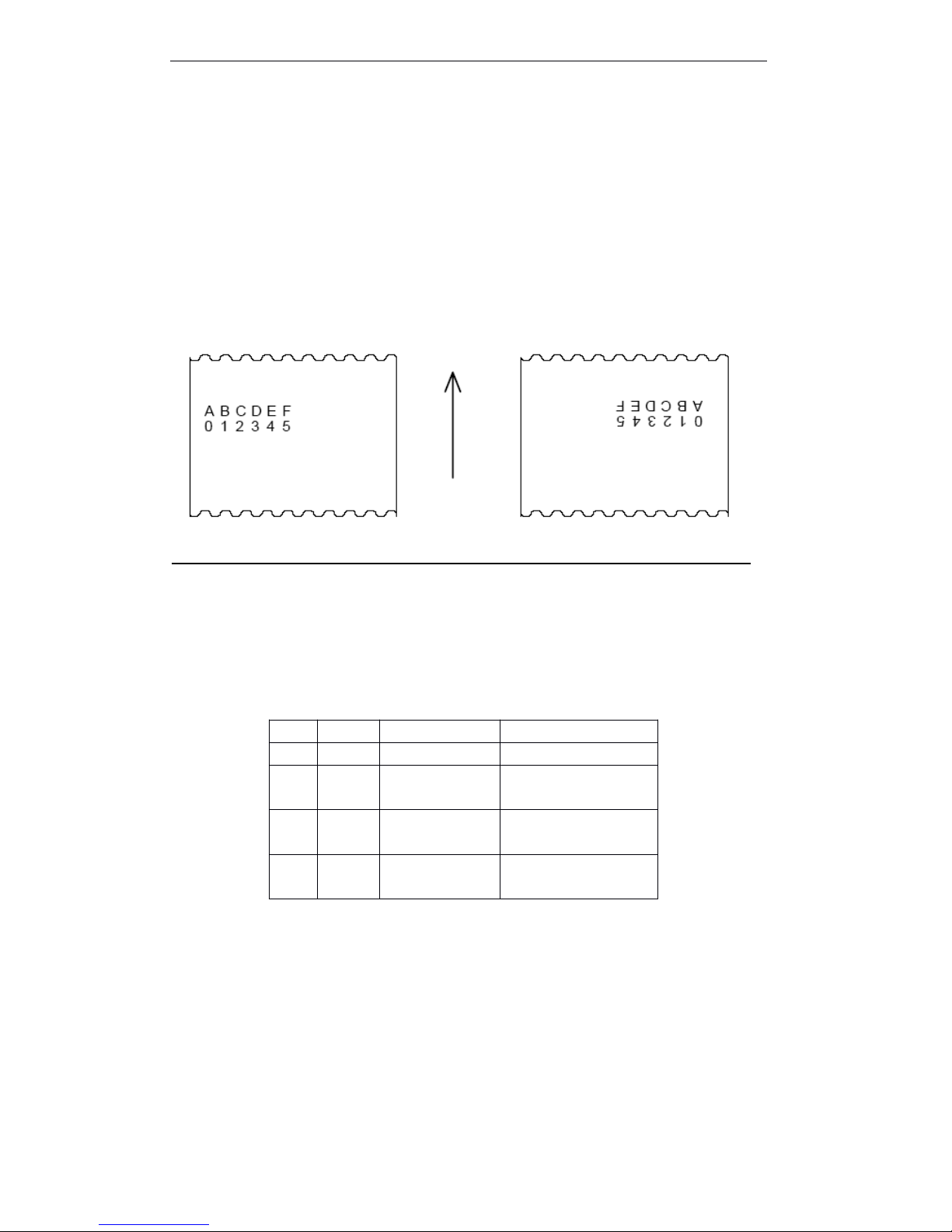
T90 User Manual
53
[ Range ] 0 ≤
n ≤
255
[ Description ] Turn upside-down print mode on/off.
· When the LSB of n is 0, upside-down print mode is turned off.
· When the LSB of n is 1, upside-down print mode is turned on.
[ Notes ] · Effect when the LSB of n.
· This command effects only when input at the starting of a line in stable mode.
· This command can not affect the print in page mode.
· In upside-down mode, the printer rotates 180 ° to the line which need to print, then
printing.
[ Default ] n = 0
[ Examples ]
解除颠倒打印模式 设置颠倒打印模式
P aper direction
FS
FS
FS
FS p
p
p
p n
n
n
n m
m
m
m
[Name] Print NV bit image
[Format] ASCII FS p n m
Hex 1C 70 n m
Decimal 28 112 n m
[Range] 1 ≤
n ≤
255
0 ≤
m ≤
3 , 48 ≤ m ≤
51
[Description] Prints NV bit image n using m.
dpi: per 25.4 mm {1 inch } print dot
· n is the quantity of NV bit image ( defined by ES q).
· m specify bit image mode
[Pa rticularize] · NV bit image defined bit image in NVM. Define by FS q, print by FS P.
· When the appointed NV bit image absent, this command is invalid.
· In stable mode, this command effects only when there are no data in buffer area.
· In page mode, this command is invalid.
· This command do not effected by print mode ( bold print , overlap print , underline
,
character size , anti-white print or character 90 rotation etc. ), except reversal prin t
mode.
m
Mode
Vertical direction
Horizontal direction
0, 48
Normal
203.2 dpi
203.2 dpi
1, 49
Double
-width
203.2 dpi
101.6 dpi
2, 50
Double
-height
101.6 dpi
203.2 dpi
3, 51
Quadru
ple
101.6 dpi
101.6 dpi
Page 60

T90 User Manual
54
· If set the NV bit image print area width which is less than a vertical line by GS L and
GS W, Executes the following operation only for problem line. In NV bit image
mode, a vertical line means the dot of normal mode ( m = 0, 48) and double height
mode ( m = 2, 50) , two dots of double width mode ( m = 1, 49) and quadruple mode
( m = 3, 51) .
① In NV bit image mode, the print area width extendes to right to a vertical line. In
this case, print can not over the print area.
② If the print area width can not extend to a vertical line, the left blank decreases to
contain a vertical line.
· If the download bit image overs one line, do not print the over data.
· In normal and double width mode, this command feed paper n dots, n is the height
of NV bit image, In double height and qu adruple mode, this command feed paper
2n dots, n is NV bit image height, do not related with the line spacing which set by
ESC 2 and ESC 3.
· After printing bit image, this command set the print position at the original of one
line, and deal with the continued data as normal data.
[Reference] ESC
ESC
ESC
ESC *
*
*
* , FS
FS
FS
FS q
q
q
q , GS
GS
GS
GS /
/
/
/ , GS
GS
GS
GS v
v
v
v 0
0
0
0
FS
FS
FS
FS q
q
q
q n
n
n
n [xL
[xL
[xL
[xL xH
xH
xH
xH yL
yL
yL
yL yH
yH
yH
yH d1...dk]1...[xL
d1...dk]1...[xL
d1...dk]1...[xL
d1...dk]1...[xL xH
xH
xH
xH yL
yL
yL
yL yH
yH
yH
yH d1...dk]n
d1...dk]n
d1...dk]n
d1...dk]n
[ Name ] Define NV bit image
[ Format ] ASCII FS q n [xL xH yL yH d1...dk]1...[xL xH yL yH d1...dk]n
Hex 1C 71 n [xL xH yL yH d1...dk]1...[xL xH yL yH d1...dk]n
Decimal 28 113 n [xL xH yL yH d1...dk]1...[xL xH yL yH d1...dk]n
[ Range ] 1 ≤ n ≤
255
0 ≤
xL ≤ 255
0 ≤ xH ≤
3 ( when 1 ≤ ( xL +
+
xH ×
256) ≤
1023
0 ≤
yL ≤
255
0 ≤
yH ≤
1 ( when 1 ≤ ( yL + yH ×
256) ≤
288
0 ≤
d ≤
255
k = ( xL + xH ×
256) ×
( yL +
+
yH × 256) ×
8
Total defined data area = 192K byte
[ Description ] Set NV bit image by specified n.
· n specify the quantity of NV bit image .
· xL , xH for defined NV bit image points the dot of horizontal direction ( xL +
+
xH ×
256 )
× 8 .
· yL , yH for defined NV bit image points the dot of vertica direction ( yL + yH ×
256)
×
8 .
[ Particularize ] This command cancels all defined NV bit image by this command. The definded
data, the printer can not defind anyone of data repeatly. If repeat certain data, so
all data should be sent once again.
· During deal with this command to finish reseting hardware, can not execute
mechanism operation ( contains when the cover is open to initialize the print hea d
position, feed paper by feed paper button etc. ) .
· During deals with this command, when writing data to user NV memory, the printer
is busy and stop receiving data. So forbid to transmit data during execute this
command, contain real-time command.
Page 61

T90 User Manual
55
· NV bit image is one bit image which definds in NVM. Prints by FS p which defined
by FS q.
· In stable mode, This command only effecs on the original line.
· In page mode, this command is invalid.
· The 7 bytes <FS ~ yH> of this command, after normal dealing with, this command
effecs.
·
. When the data quantity overs the left capacity range, the printer processes the range
which defined by xL, xH, yL, yH.
. · At the first group bit image, when any parameters in xL, xH, yL, yH overs the defined
range, this commandisdisabled.
.At any one of group bit image except for the first group, when the printer meets that
xL,xH, yL, yH overs the defined scale, stops processing this command, and begins to
write NV image. At this moment, the undefined NV bit image (undefined)is disabled,
butany NV bit image defined before always affects.
.d indicates defined data. At the data (d), one bit specifies one dot which need to
print and one 0 bit specifies one dot which do not need to print.
.This command put n to define as the quantity o NV bit image. The quantity goes up
from bit image 01H. So the first data group [xL xH yL yH dl...dK]isthe NV bit image
01H. The last data group [xL xH yL yH dl...dK]isthe NV bit image n. The total the
s ame as the NV bit image quantity which be set by FS p.
. One NV bit image defined data consists of [xL xH yLl xH dl...dK]. So, when only has
one NV bit image n=1, the printer only processes the data group [xl xH yL yH
dl...dK] once. The printer uses ([data:(xL+xH × 256) × (yL+yH × 256) × 8]+[header:4])
bytes of the NV memory.
.The definded area of this printeris192K bytes (max). This command can define
several bit images, but can ’tdefine the bit image which the total capacity [bit image
data+head] overs 192K bytes.
.Whatever how to set DIP switch 2-1, the printer enters “ busy ” before writing NV
memory.
.Even set ASB, the printer do not send the ASB status or execute status test during
process this command.
.When receive this command during macro definition, the printer stops macro
definition and executes this command.
.Once defines one NV bit image,itcan ’tbe executed ESC @, and deleted when reset
and power off.
.This command only executes the definition of NV bit image, do not execute print. NV
bit image print executed by FS p.
[Notes] . Writes command frequently which could be broken the NV memory.
So, suggests that executes the written operation less than ten times.
.After the process of putting one bit image into NV memory, the printer executes one
hardware reset operation. So, defines the user-defined character, download bit
image and macro after finishing this command. The printer clears receive and print
buffer a rea, and reset to the effective mode when turing the power on. At this
moment, the switch DIP set will be checked once again.
[Reference] FS p
[Examples] When xL = 64, xH = 0, yL = 96, yH = 0
Page 62
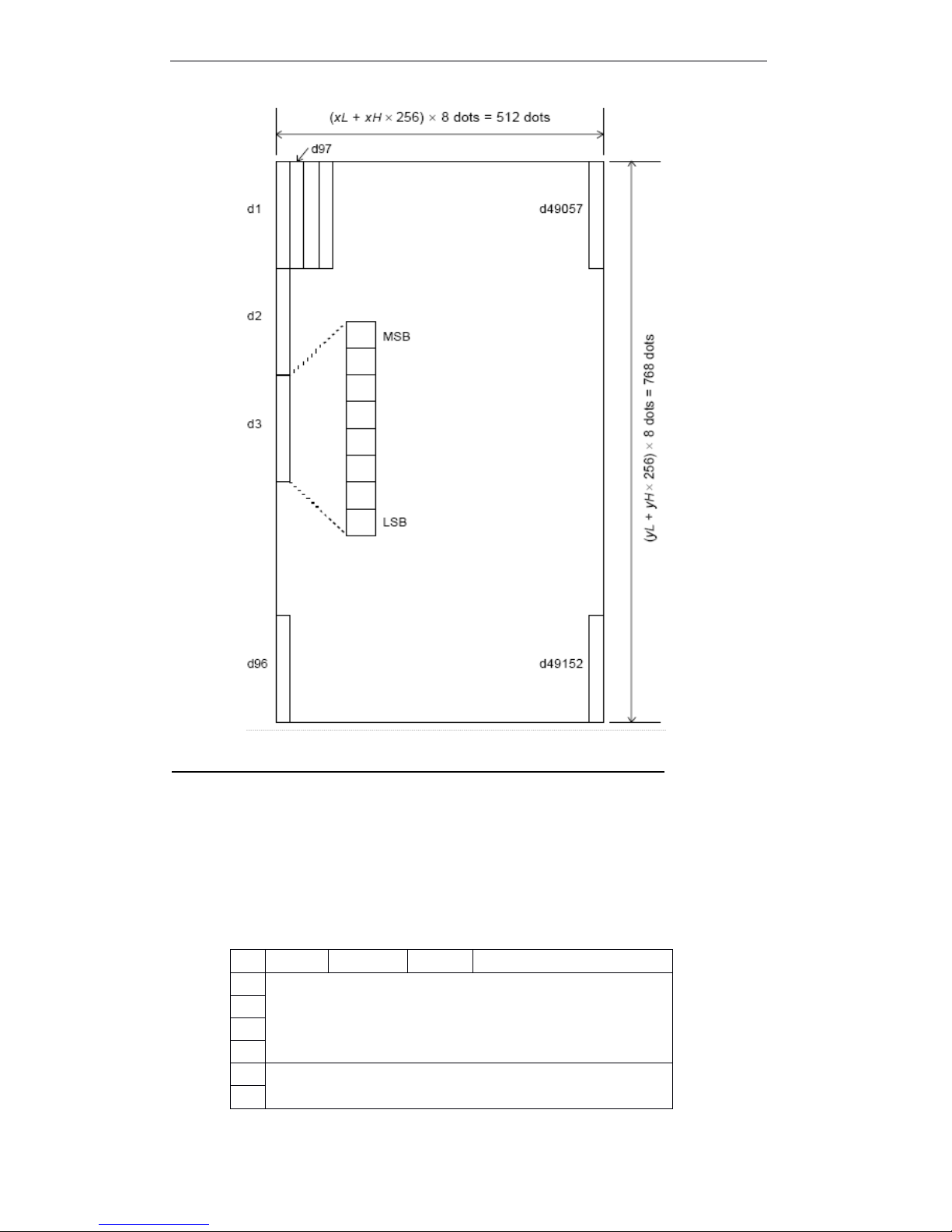
T90 User Manual
56
GS
GS
GS
GS !
!
!
! n
n
n
n
[ Name ] Select character size
[ Format ] ASCII GS ! n
Hex 1D 21 n
Decimal 29 33 n
[ Range ] 0 ≤
n ≤ 255
(1 ≤
vertical ≤
8, 1 ≤ horizontal ≤ 8)
[ Description ] Set character height by 0-2, character width by 4-6. As follows:
Bit
Off / on
Hex
Decimal
Function0Set character height. S ee table 2.
1
234
Set character width. S ee table 1.
5
Page 63
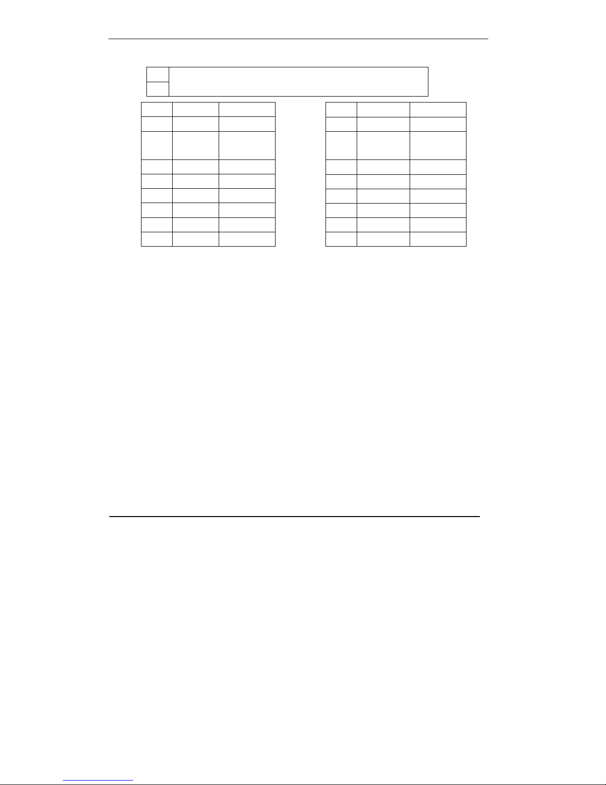
T90 User Manual
57
T able 1 Table 2
Set character width Set character height
[Notes] .This command affects to all characters (English characters and Chinese) except for
HRI character.
.If nisout of the definition scale, this command will be ignored.
· . In stable mode, the vertical direction
is
the feed paper direction. However, when
thecharacter direction rotates clockwise 90 °,the vertical direction and horizontal
direction will be reversed.
.In page mode, the vertical direction and horizontal direction are on basis of the
character direction.
.When enlarging the characters in a line by the different size, all characters in a line will
be paralleled along the baseline.
.Turn double width and height mode by ESC !. The set of command which received
at
last will be affected.
[Default] n = 0
[Reference] ESC
ESC
ESC
ESC !
!
!
!
GS
GS
GS
GS $
$
$
$ nL
nL
nL
nL nH
nH
nH
nH
[ Name ] Set absolute vertical print position in page mode
[ Format ] ASCII GS $ nL nH
Hex 1D 24 nL nH
Decimal 29 36 nL nH
[ Range ] 0 ≤
nL ≤
255, 0 ≤
nH ≤ 255
[Description] .In page mode, sets absolute vertical print starting position for buffer data.
.This command sets the absolute print position
at
[(nL+nH × 256) × 0.125 ㎜ ].
[Notes] .This command only affects in page mode.
.If [(nL+nH × 256) × (vertical or horizontal moving unit)] overs the specified print area,
this command will be ignored
.The position of horizontal starting buffer area won ’tbe moved.
.The reference starting position specifies by ESC
T.
.The operation of this command as follows, decides by the printable area starting
position which set by ESC
T:
6
7
Hex
Decimal
Width
0001( Standard )
10162( Double
width )2032
3
304844064550806
60967701128Hex
Decimal
Width000
1( Standard )
0112( Double
height )
022303340445055
6
0667077
8
Page 64

T90 User Manual
58
① When the starting position sets at the up-left or down-right , this command sets the
absolute position in the vertical direction.
② When the starting position sets at the up-right or down-left, this command sets the
absolute position in the parallel direction.
[Reference] ESC
ESC
ESC
ESC $
$
$
$ , ESC
ESC
ESC
ESC T
T
T
T , ESC
ESC
ESC
ESC W
W
W
W , ESC
ESC
ESC
ESC \
\
\
\ , GS
GS
GS
GS \
\
\
\
GS
GS
GS
GS (
(
(
( A
A
A
A pL
pL
pL
pL pH
pH
pH
pH n
n
n
n m
m
m
m
[ Name ] Execute test print
[ Format ] ASCII GS ( A pL pH n m
Hex 1D 28 41 pL pH n m
Decimal 29 40 65 pL pH n m
[ Range ] (pL+(pH × 256))=2 (pL=2, pH=0)
0 ≤ n ≤
2, 48 ≤
n ≤
50
1 ≤
m ≤
3, 49 ≤
m ≤ 51
[ Description ] Executes the test print at the specified printing paper and uses
the
specified mode.
·
pL and pH specify (pL + (pH ×
256)) as the number of bytes.
n specifies the paper used for the test print
m specifies a test pattern
[ Particularize ] .This command only affectsatthe beginning of a line in stable mode.
. This commandsisinvalid in page mode.
.When receiving this command during macro definition, the printer finishes the macro
definition and begins to execute this command.
.The printer reset automatically after finishing printing. Therefore, the defined data
before executing this command, For example, the user-defined character, download
bit image and macro will change to be undefined; Receive buffer area and print
buffer area will be cleared; all set will be returned to default data. The printer read the
DIP switch set again.
.The printer cuts the paper when finishing test print.
.During executes this commands, the printer enters into “ BUSY ” status.
GS
GS
GS
GS *
*
*
* x
x
x
x y
y
y
y d1..d(
d1..d(
d1..d(
d1..d( x
x
x
x y
y
y
y 8
8
8
8 )
)
)
)
[Name] Defines down-load bit image
[Format] ASCII GS
*
x y d1...d( x ´ y ´ 8 )
n
Paper
0, 48
Basic sheet ( roll paper )
1, 49
2, 50
Roll paper
m
Test pattern
1, 49
Hexadecimal dump print
2, 50
Printer status print
3, 51
Rolling pattern print
Page 65
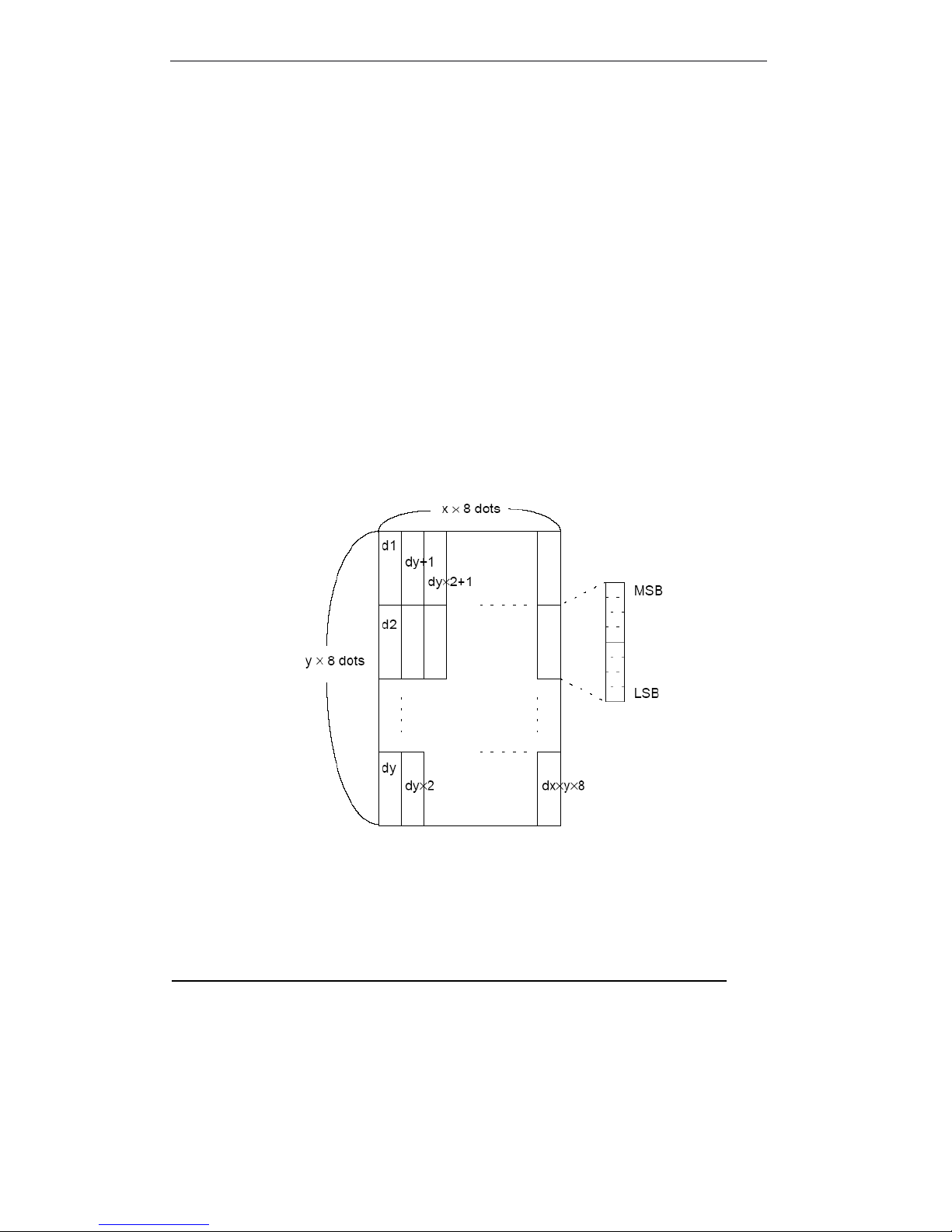
T90 User Manual
59
Hex 1D 2A x y d1...d( x ´ y ´ 8 )
Decimal 29 42 x y d1...d( x ´ y ´ 8 )
[Range] 1 ≤ x ≤
255
1 ≤
y ≤
48 (x ×
y ×
1536)
0 ≤
d ≤ 255
[Description] Specifies dot by x and y, and defines the down-load bit image.
· x specify horizontal dot.
· y specify vertical dot.
[Notes] · Horizontal direction dot is x ×
8 ; Vertical direction dot is y ×
8.
· When x ×
y overs the defined range, this command is disabled.
· d
indicates bit image dat. Data
(d) specifies that print bit is 1,Do not print bit that i s
0.
· In following case, clear down-load bit image definition :
① Executes ESC
ESC
ESC
ESC @
@
@
@ .
② Executes ESC
ESC
ESC
ESC &
&
&
& .
③ The printer reset or turn the power of.
· The connection between down-load bit image and print data as follows.
[Reference] GS
GS
GS
GS /
/
/
/
GS
GS
GS
GS /
/
/
/ m
m
m
m
[ Name ] Prints down-load bit image
[ Format ] ASCII GS / m
Hex 1D 2F m
Decimal 29 47 m
[ Range ] 0 ≤ m ≤
3, 48 ≤
m ≤
51
[ Description ] Prints down-load bit image by mode which defines by m.
Page 66

T90 User Manual
60
m set mode from following table :
dpi: per 25.4 mm {1inch}
[Notes] .If the bit image data has not defined, then this command will be ignored.
.In stable mode, this command affects only when there are no data in the printing buffer
area.
.This command
is
invalid in print mode [bold, overlap, underline, character size or reverses
blank printing], except for up-down printing mode.
.If the download bit image which will be printed overs the printable area, then the over data
can not print.
.If the printable width which set by GS L and GS W
is
less than the asked width by GS to
send the data, then executes the following continued operation for the problem lines [the
print can not over the max printable area].
① The width of the printable area which extends to the right and holds the data
capacity.
② If the step ① can ’tprovided enough width for data, then narrows the left blank to
hold the data.
Each data in stable mode (m=0, 48) and double height mode (m=2,50), the printer
prints one dot;
Each data under the double width mode (m=1, 48) and four double mode (m=3, 51),
the printer prints two dots.
[Reference] GS
GS
GS
GS *
*
*
*
GS
GS
GS
GS :
:
:
:
[Name] Start/end macro definition
[Format] ASCII GS :
Hex 1D 3A
Decimal 29 58
[Description] Start/end macro definition
[Notes] .When receiving this command in stable operation, starts macro definition. When receiving
this command during macro definition, finishes the macro definition.
.During macro definition, when receiving GS
^,
the printer stops macro definition and clears
macro definition.
.When turns the power on, undefined macro.
.ESC @ does not clear the content of macro definition. So, ESC @ could be contained in
macro definition.
.If the printer receives GS :,then receiving GS promptly,the printer stops on undefined
macro definition.
m
Mode
Vertical dot
density
Horizontal dot density
0, 48
Stable
203.2 dpi
203.2 dpi
1, 49
Double
width
203.2 dpi
101.6 dpi
2, 50
Double
height
101.6 dpi
203.2 dpi
3, 51
Quadruple
101.6 dpi
101.6 dpi
Page 67

T90 User Manual
61
.The content of macro definition reaches to 2048 bytes. If the content of macro definition
overs 2048 bytes, soitcan not store the over part of data.
[Reference] GS
GS
GS
GS ^
^
^
^
GS
GS
GS
GS B
B
B
B n
n
n
n
[Name] Turn white/black reverse print mode on/off
[Format] ASCII GS B n
Hex 1D 42 n
Decimal 29 66 n
[Range] 0 ≤
n ≤
255
[Description] Turn white/black reverse print mode on/off.
· When the LSB of n is 0, turn white/black reverse print mode off.
· When the LSB of n is 1, turn white/black reverse print mode on.
[Notes] · Only the LSB of n is valid.
.This command to inner characters and user-defined characters are valid.
.Turns white/black reverse print mode on, blank area which set by ESC SP
is
also valid.
.This command no affects to bit image, user-defined bit image, bar code, HRI character,
and the space skipped by
HT,
ESC $ and ESC ﹨ .
.This command do not affect bit image, user-defined bit image, bar code, HRI character,
skim space by
HT,
ESC
ESC
ESC
ESC $
$
$
$ and ESC
ESC
ESC
ESC \
\
\
\ 。
.This command can not affect line spacing.
.The white/black reverse print mode take precedence of underline mode. When setting
white/black reverse print mode, even turn the underline mode on which will also be
disabled [but do not cancel].
[Default] n = 0
GS
GS
GS
GS C
C
C
C 0
0
0
0 n
n
n
n m
m
m
m
[Name] Set attribute value print mode
[Format] ASCII GS C 0 n m
Hex 1D 43 30 n m
Decimal 29 67 48 n m
[Range] 0 ≤
n ≤
5
0 ≤
m ≤
2, 48 ≤
m ≤
50
[Description] Continued attribute value print mode.
· n will set the figure, the number as follows:
When n = 0, The printer prints actual value.
When n = 1 to 5, This command sets the figure number.
· m set print position in all range, as follows:
m
Print
position
Process the figure less
than the pointed bit
digit
0, 48
Right
Add blank to left
1, 49
Right
Add 0 to left
Page 68
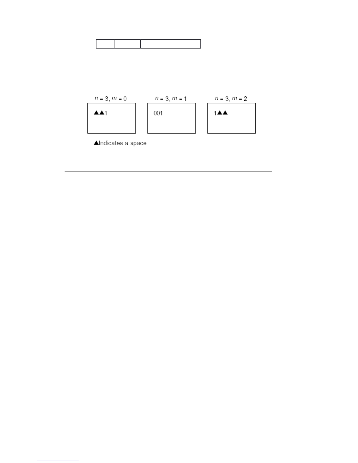
T90 User Manual
62
[Notes] · If n or m overs defined range, the original print mode is the same as before.
· If n = 0 , m has not any meaning.
[Default] n = 0, m = 0
[Reference] GS
GS
GS
GS C
C
C
C 1
1
1
1 , GS
GS
GS
GS C
C
C
C 2
2
2
2 , GS
GS
GS
GS C
C
C
C ;, GS
GS
GS
GS c
c
c
c
[Examples]
GS
GS
GS
GS C
C
C
C 1
1
1
1 aL
aL
aL
aL aH
aH
aH
aH bL
bL
bL
bL bH
bH
bH
bH n
n
n
n r
r
r
r
[Name] Select attribute value print mode (A)
[Format] ASCII GS C 1 aL aH aL bH n r
Hex 1D 43 31 aL aH aL bH n r
Decimal 29 67 49 aL aH aL bH n r
[Range] 0 ≤
aL ≤
255
0 ≤ aH ≤
255
0 ≤
bL ≤
255
0 ≤
bH ≤
255
0 ≤ n ≤
255
0 ≤
r ≤ 255
[Description] .Select attribute value print mode.
· aL, aH or bL, bH specify attribute value range.
· When increase or decrease by degrees, n specify step value.
· When attribute value fixed, r indicates repeat times.
[Notes] If meet the following conditions, set increase by degrees:
[aL + aH ×
256] < [bL + bH ×
256] and n ≠ 0 and r ≠
0
· If meet the following conditions, set decrease by degrees:
[aL + aH ×
256] > [bL + bH ×
256] and n ≠
0 and r ≠
0
· If meet the following conditions, stop count :
[aL + aH ×
256] = [bL + bH × 256] and n ≠ 0 and r ≠
0
· Set increase by degrees count, the min data is [aL + aH × 256] , the max is [bL +
bH ´ × 256]. If the count data overs the max data, return s min data to count
repeatly.
· Set decrease by degree mode, the min data is [aL + aH × 256] , the min is[bL +
bH ´ ×
256]. If the count data decreases to min data, return max data to count
repeatly.
· When executing this command, clear the inner count by r.
[Default] aL = 1, aH = 0, bL = 255, bH = 255, n =1, r = 1
[Reference] GS
GS
GS
GS C
C
C
C 0
0
0
0 , GS
GS
GS
GS C
C
C
C 2
2
2
2 , GS
GS
GS
GS C
C
C
C ;, GS
GS
GS
GS c
c
c
c
2, 50
Left
Add blank to right
Page 69

T90 User Manual
63
GS
GS
GS
GS C
C
C
C 2
2
2
2 nL
nL
nL
nL nH
nH
nH
nH
[Name] Set attribute value
[Format] ASCII GS C 2 nL nH
Hex 1D 43 32 nL nH
Decimal 29 67 50 nL nH
[Range] 0 ≤
nL ≤
255
0 ≤ nH ≤
255
[Description] Set serial attribute data.
· nL and nH define the attribute value as [nL + nH ×
256].
[Notes] · In increase by degrees, if the attribute value overs the operation range by GS
GS
GS
GS C
C
C
C 1
1
1
1 or
GS
GS
GS
GS C
C
C
C , changes to the min value by GS c.
· In decrease by degrees, if the attribute value overs the operation range by GS
GS
GS
GS C
C
C
C 1
1
1
1
or GS
GS
GS
GS C
C
C
C , changes to the max value by GS c.
[Default] nL = 1, nH = 0
[Reference] GS
GS
GS
GS C
C
C
C 0
0
0
0 , GS
GS
GS
GS C
C
C
C 1
1
1
1 , GS
GS
GS
GS C
C
C
C ;, GS
GS
GS
GS c
c
c
c
GS
GS
GS
GS C
C
C
C sa
sa
sa
sa sb
sb
sb
sb sn
sn
sn
sn sr
sr
sr
sr sc
sc
sc
sc
[ Name ] Select attribute value mode (B)
[ Format ] ASCII GS C ; sa ; sb ; sn ; sr ; sc ;
Hex 1D 43 3B sa 3B sb 3B sn 3B sr 3B sc 3B
Decimal 29 67 59 sa 59 sb 59 sn 59 sr 59 sc 59
[ Range ] “ 0 ” ≤
sa ≤
“
65535 ”
“ 0 ” ≤
sb ≤ “ 65535 ”
“ 0 ” ≤
sn ≤
“
255 ”
“ 0 ” ≤ sr ≤
“
255 ”
“ 0 ” ≤
sc ≤
“
65535 ”
A bove value are character strings.
[ Description ] Select one attribute value for attribute counter, and points the attribute value.
· sa, sb, sn, sr and sc to show ASCII characters, uses the code from “ 0 ” to “ 9 ” .
· sa and sb specify attribute value range.
· sn indicates the step space of increase or decrease by degrees.
· sr indicates repeat times, attribute value is fixed.
· sc indicates attribute value.
[Notes] · Meet the following conditions, increase by degrees attribute mode:
sa < sb and sn ≠
“
0 ” and sr ≠
“
0 ”
· Meet the following conditions, decrease by degrees attribute mode:
sa > sb and sn ≠
“
0 ” and sr ≠
“
0 ”
· Meet the following conditions, stops attribute value:
sa = sb or sn = “ 0 ” or sr = “ 0 ”
.Specifies the mode of increase by degrees, saisthe min count value, sb
is
the max. If
the increase counts value overs the max value, the count value returns to the min
value and begins again. If the count value set by sc which overs the counter
operati on scale, will change the count value to min value through executing GS c.
.Specifies the mode of decrease by degrees, saisthe max count value,
sb
is
the min count value. If the decrease count value overs the min count value,the
count value returns to the max value and begins again. If the count value set by sc
Page 70
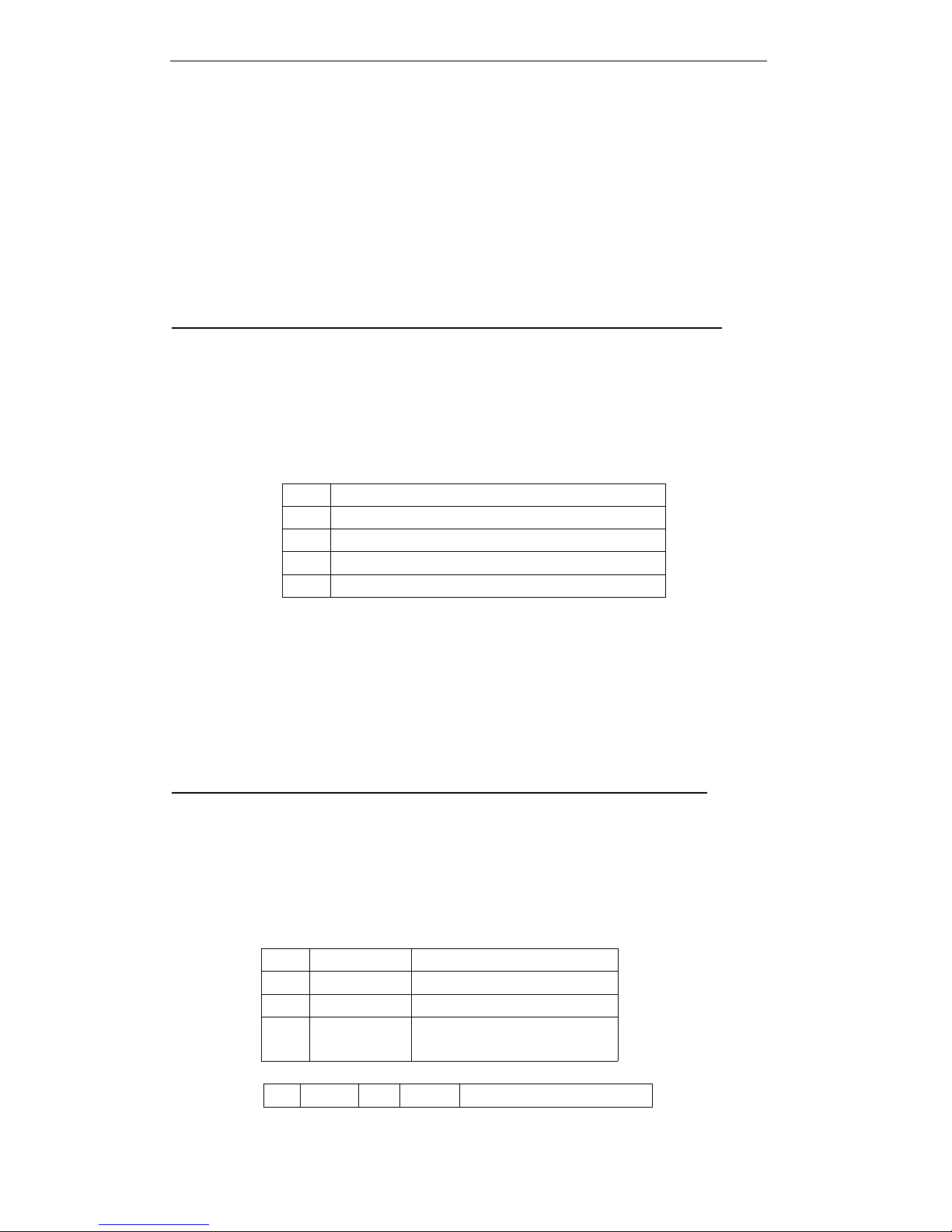
T90 User Manual
64
which overs the counter operation scale, will change the count value to max value
through executing GS c.
.Could omit parameter sa to sc. If omitting, then these parameter value won ’tchange.
.The parameter sa to sa wh at c ouldn ’tcontain another characters out of the “ 0 ” to “ 9 ” .
.If the grammariswrong, so the relevant parameters settingisinvalid, and processes the
following data as the normal data.
[Default] sa = “ 1 ” , sb = “ 65535 ” , sn = “ 1 ” , sr = “ 1 ” , sc = “ 1 ”
[Reference] GS
GS
GS
GS C
C
C
C 0
0
0
0 , GS
GS
GS
GS C
C
C
C 1
1
1
1 , GS
GS
GS
GS C
C
C
C 2
2
2
2 , GS
GS
GS
GS c
c
c
c
GS
GS
GS
GS H
H
H
H n
n
n
n
[Name] Select print position of HRI characters
[Format] ASCII GS H n
Hex 1D 48 n
Decimal 29 72 n
[Range] 0 ≤
n ≤
3 ; 48 ≤
n ≤ 51
[Description] Print bar code, select print position of HRI characters.
n select print position, as following table:
Note
Note
Note
Note : Printing
Printing
Printing
Printing HRI
HRI
HRI
HRI character
character
character
character position
position
position
position does
does
does
does not
not
not
not set
set
set
set according
according
according
according to
to
to
to the
the
the
the standard
standard
standard
standard
position.
position.
position.
position.
· HRI ( Human Readable Interpretation ) indicates the barcode corresponding
characters.
[Note] · Print HRI character which set by GS F.
[Default] n = 0
[Reference] GS
GS
GS
GS f
f
f
f , GS
GS
GS
GS k
k
k
k
GS
GS
GS
GS I
I
I
I n
n
n
n
[Name] Transmit printer ID
[Format] ASCII GS I n
Hex 1D 49 n
Decimal 29 73 n
[Range] 1 ≤ n ≤
3, 49 ≤ n
≤ 51
[Description] Transmit printer ID.
· n indicates the type of printer ID.
[Type ID]
n
Print position
0, 48
Not print
1, 49
Above bar code
2, 50
Below bar code
3, 51
Above and below bar code
n
Printer ID type
ID
1, 49
Printer type ID
Model: T90, Hex: 21H
2, 50
Type ID
Below table
3, 51
Firmware
version ID
43H
Bit
Off/on
Hex
Decim
Function
Page 71
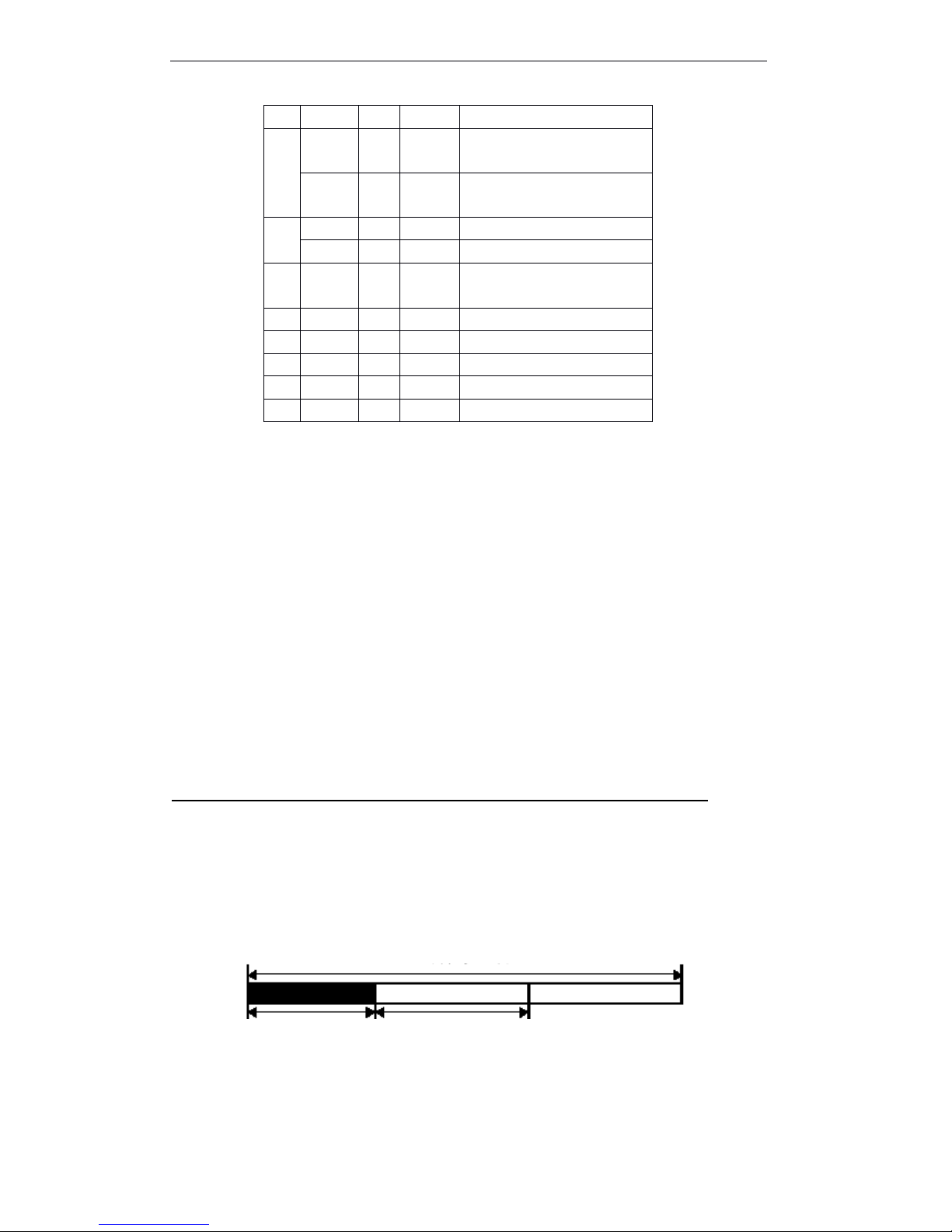
T90 User Manual
65
[Particularize] .In serial interface mode, controls by selecting DTR/DSR, be sure that the host have
ready to receive data(DSR signalisSPACE), The printer only transmits one byte. If
the host have not ready to receive data (DSR signal
is
MARK), the printer will be
waited, until the printer have ready to.
.In serial interface mode, controls by selecting XON/XOFF, the printer only transmits
one byte, but not sure that the conditions of DSR signal.
· .When spreading the data in the receiving buffer area, transmits printer ID. After
receiving this command, could be waited a period of transmitting conditions,
it
decided by the conditions of receiving buffer area.
. Enable automatically restoring (ASB) by GS
a,
must be distinguished the
conditions of transmitting by GS I and ASB.
Note
Note
Note
Note : At
At
At
At present,
present,
present,
present, no
no
no
no bit
bit
bit
bit 0
0
0
0 change
change
change
change able
able
able
able information.
information.
information.
information.
GS
GS
GS
GS L
L
L
L nL
nL
nL
nL nH
nH
nH
nH
[Name] Set left margin
[Format] ASCII GS L nL nH
Hex 1D 4C nL nH
Decimal 29 76 nL nH
[Range] 0 ≤ nL ≤ 255
0 ≤
nH ≤
255
[Description] Set left margin by nL and nH.
· Set left margin [(nL + nH × 256) × 0.125 mm].
The left side blank The width of printable width
al0OFF000
Not support double byte
character code.
ON011
Support double byte character
type.1OFF000
Uninstall auto cutter.
ON022
Install auto cutter.
2--
-
Undefined.
3---Not used.
4---Not used.5---
Undefined.
6---Undefined.
7--
Not used.
Page 72

T90 User Manual
66
[Notes] · In stable mode, this command is valid only at the line origin position.
· Input this command in page mode, the printer only executes the inner sign
operation.
· In page mode, this command can not affect the print.
· If the set overs the printable area, so uses the max printing unit.
· When execute ( GS
GS
GS
GS v
v
v
v 0
0
0
0 ) , set left margin by this command, 8 bits as unit. If the left
margin can not be deleted by 8, or, leave out remainder.
(For example ) If (nL + nH × 256) = 20, set value as 16 。
Note
Note
Note
Note : Uses
Uses
Uses
Uses this
this
this
this command
command
command
command together
together
together
together with
with
with
with GS
GS
GS
GS /
/
/
/ 、 ESC
ESC
ESC
ESC *
*
*
* ,
,
,
, print
print
print
print result
result
result
result may
may
may
may not
not
not
not the
the
the
the
expected.
expected.
expected.
expected.
[Default] nL = 0, nH = 0
[Reference] GS
GS
GS
GS W
W
W
W
GS
GS
GS
GS T
T
T
T n
n
n
n
[Name] Set print position as printing origin
[Format] ASCII GS T n
Hex 1D 54 n
Decimal 29 84 n
[Range] n = 0, 1, 48, 49
[Description] Set print position as printing origin
.n specifies the data process method in print buffer area.
① GS
GS
GS
GS V
V
V
V m
m
m
m ② GS
GS
GS
GS V
V
V
V m
m
m
m n
n
n
n
[Name] Select cut paper mode and cut paper
[Format] ① ASCII GS V m
Hex 1D 56 m
Decimal 29 86 m
② ASCII GS V m n
Hex 1D 56 m n
Decimal 29 86 m n
[Range] ① m = 1, 49
② m = 66, 0 ≤
n ≤
255
[Description] Select cut paper mode, and execute cut paper operation. Select model by m, as
follows:
[The particularize of ① and ② ]
.As the difference of the autocut type, the cut paper statusisdifferent.
.This command affects only when processing this command
at
the printing origin.
[The particularize for ① ]
Only partial cut; notfull cut.
n
Print position
0, 48
Delete all data in print area, then set print position as printing
origin
1, 49
Print all data in print area, then set print position as printing
origin
Page 73
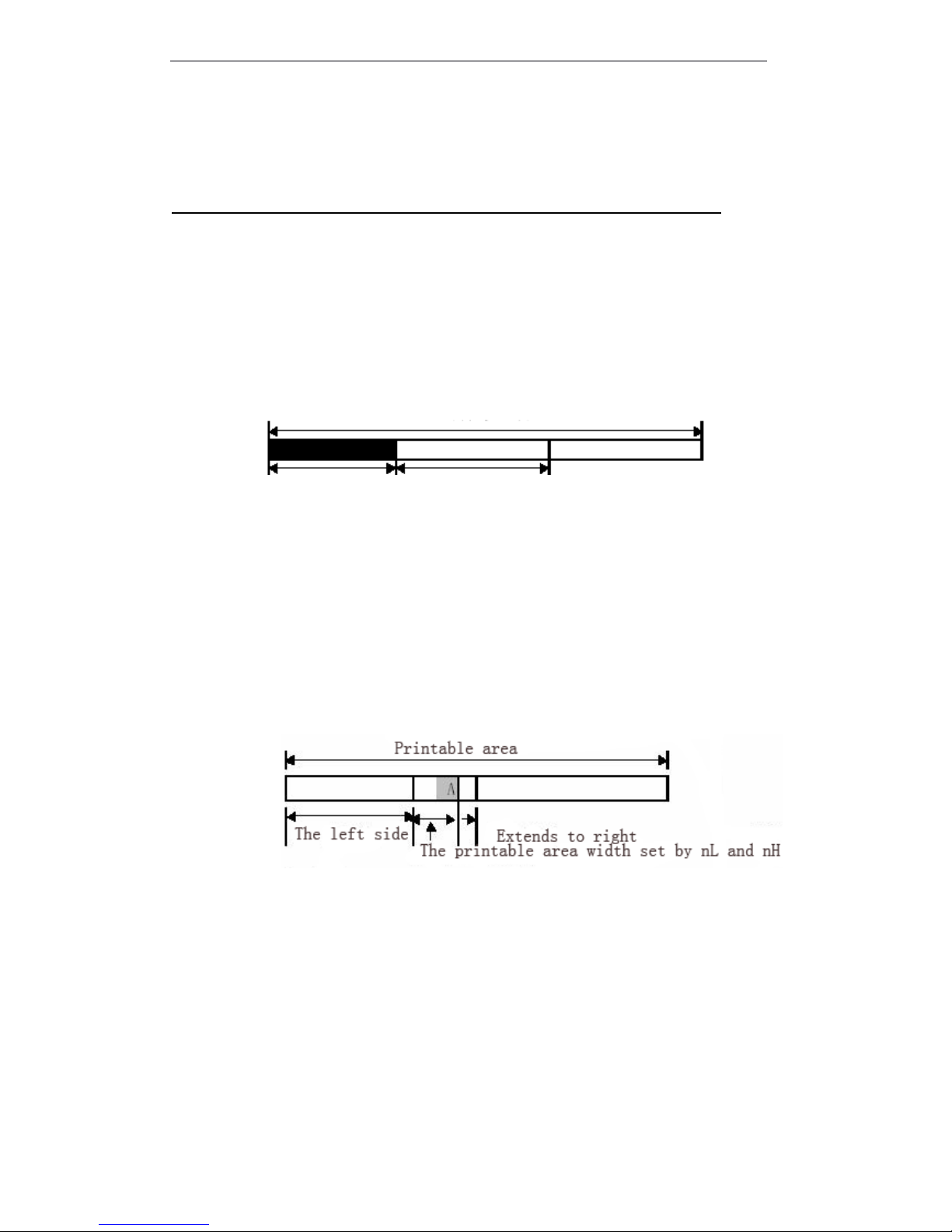
T90 User Manual
67
[The particularize for ② ]
When n ≠0,the printer feeds paper to (cut paper position+[n × 0.125 ㎜ {0.0049 inch}]
and cut paper.
GS
GS
GS
GS W
W
W
W nL
nL
nL
nL nH
nH
nH
nH
[Name] Set pirnt area width
[Format] ASCII GS W nL nH
Hex 1D 57 nL nH
Decimal 29 87 nL nH
[Range] 0 ≤
nL ≤
255
0 ≤
nH ≤
255
[Description] Set print area width by nL and nH.
· Set print area width as [(nL + nH × 256) × 0.125mm].
Printable area
The left side blank The width of printable width
[Notes] · This command only affects when processing the line origin.
· If input this command in page mode, The printer executes inner sign operation.
· This command does not affect printing in page mode.
· If set value overs the printable area, uses the max vaule of printable value.
· The set priority of GS W
is
higher than GS L. If [Left blank+printable area width]
overs the printable area, the printer uses [printable area width- left blank]. However,
do not use the set which sets by GS W,reserve the set which sets by GS W.
If the printable area width set whichissmaller than one character width, when
printing character data, execute the following steps:
① The printable area width extends to right to meet one character.
② If printable area width couldn ’tbe extended
fully,
decrease left page to meet one
character.
③ If printable area width couldn ’ t be extended fully, decrease right spacing.
· If printable area widthissmaller than one vertical line, when printing non-character
data (for example, bit image, the user-defined bit image),only process the problem
lines as follows:
①
Extend printable area width to right and meet one vertical line of bit image in the
printable area.
②
If printable area width couldn ’tbe extended
fully,
decrease left page to meet one
vertical line.
Page 74

T90 User Manual
68
[Default]
[Reference] GS
GS
GS
GS L
L
L
L
GS
GS
GS
GS \
\
\
\ nL
nL
nL
nL nH
nH
nH
nH
[Name] Set relative vertical print position in page mode
[Format] ASCII GS \ nL nH
Hex 1D 5C nL nHf
Decimal 29 92 nL nH
[Range] 0 ≤
nL ≤
255
0 ≤
nH ≤
255
[Description] Set the present position as relative vertical print position in page mode. The distance set
by this command from the present position to [(nL+nH × 256) × 0.125 ㎜ ].
[Notes] If do not select page mode, this command ignored.
When N specified as the downward move:
nL+nH × 256=N
When N specified as the upward move (negative direction), uses 65536 complement code .
When N specified as the upward move:
nL + nH × 256 = 65536 - N
.Any set what overs the specified printable area which will be ignored.
.As the print origin position set by ESC
T,
this command functions as follows:
① When setting the origin position to up-left or down-right of printable area, uses the
vertical move unit(y).
② When setting the origin position to up-right or down-left of printable area, uses the
horizontal move unit(x).
[Reference] ESC
ESC
ESC
ESC $
$
$
$ , ESC
ESC
ESC
ESC T
T
T
T , ESC
ESC
ESC
ESC W
W
W
W , ESC
ESC
ESC
ESC \
\
\
\ , GS
GS
GS
GS $
$
$
$
GS
GS
GS
GS ^
^
^
^ r
r
r
r t
t
t
t m
m
m
m
[Name] Execute macro
[Format] ASCII GS ^ r t m
Hex 1D 5E r t m
Decimal 29 94 r t m
[Range] 0 ≤
r ≤
255
0 ≤
t ≤
255
m = 0, 1
[Description] Execute macro
· r specifies times of executing macro.
· t
specifies the waiting time of operating macro.
.m specifies the macro executed mode.
Mode type
Horizont
al dot
Default
(82.5 mm paper width type )
640 dot
nL = 128, nH = 2
(79.5 mm paper width type )
576 dot
nL = 64, nH = 2
(60 mm paper width type )
448 dot
nL = 192, nH = 1
(58 mm paper width type )
432 dot
nL = 176, nH = 1
Page 75

T90 User Manual
69
When the LSB of
m is
0:
Macro continues to execute r timesatthe specified time spacing.
When the LSB of
m is
1:
After the waiting time which specifies byt,PAPER OUT LED will be flashed, and the
printer be waited, FEED button will be pushed. After pushing the button, the printer
executes macro one time. The printer operates r times repeatly.
[Notes]
.
Executes macro one time, the waiting timeist × 100ms.
.
If receive this command when defining one macro, so the macro definition will be failed
and the definition will be cleared.
.
If do not define macro or r
is 0,
do not execute any operation.
.
When operating macro(m=1), feed paper can ’tbe taken by FEED button.
[Reference] GS
GS
GS
GS :
:
:
:
GS
GS
GS
GS a
a
a
a n
n
n
n
[Name] Enable/disable automatic status back (ASB)
[Format] ASCII GS a n
Hex 1D 61 n
Decimal 29 97 n
[Range] 0 ≤
n ≤
255
[Description] Enable/disable ASB and n specifies the contained items,
As follows:
[Notes] .If any one of status items in the above table
is
enabled, so execute this command and the
printeristransmission status. Once the enabled statuss changes, the printer transmits statuss
automatically. Because each status transmission means the current st atus, So, the disabled
status could be changed.
.If all status items are disabled, the ASB function also be disabled.
.If ASB set to default set, so when the printer be opened to receive and transmit the data, the
printer transimts the data.
.Transmit the following four status bytes, do not need to sure whether the host have ready to
receive the data or not. The four status bytes have to be continued, except for the XOFF
code.
Bit
Off/OnHex
Deciaml
ASB Status
0
Off000
O ff is fixed .
1
OffOn000Disable online/offline status.
022Enable online/offline status.
2
Off
On
000Disable error status.
044Enable error status.
3
OffOn000Disable roll paper sensor.
088Enable roll paper sensor.
4--
Undefined.5--Undefined.
6
Off
On
000Disable roll paper “ FEED ” .
4064Enable roll paper “ FEED ”
7---Undefin ed .
Page 76
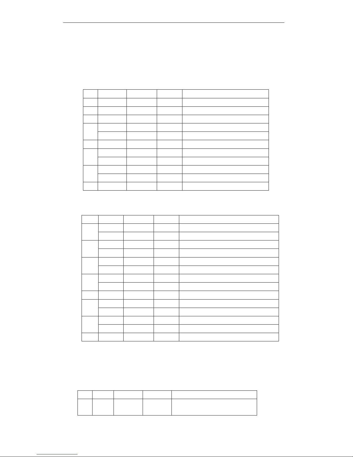
T90 User Manual
70
.Because the data processed in the receiving buffer area and executed later, so there are one
period of lag time between date receiving and condition transmission.
.When uses DLE EOT or GS
r,
have to distinguish the transmission status and ASB status,
according to appendix C, the process of transmission status in read.
.The transmission status items as follows:
The first type (the printer information)
The second type (the printer information)
Bit 0 : refer to DLE
DLE
DLE
DLE EOT
EOT
EOT
EOT .
Bit 2 : refer to DLE
DLE
DLE
DLE EOT
EOT
EOT
EOT .
Bit 6: The printer stops printing as the over temperature of print head, bit 6 is ON, until the
temperature is normal or open the cover when printing.
Recover printing , Bit 6 is OFF.
The third byte (roll paper sensor information)
Bit
Off/On
Hex
Decimal
ASB Status
0
Off000
Off is fixed.
1
Off000
Off is fixed.
2On044Undefined, On is fixed.
3
Off000
Online.On088Offline.
4On1016On is fixed5Off000
Close the cover.
On2032
Open the cover.
6
Off000
Disable roll paper “ FEED ” .
On4064
Enable roll paper “ FEED ” .
7
Off000
Off is fixed.
Bit
Off/On
Hex
Decimal
ASB Status
0
Off000
Offline wait status.
On011
Online wait status.
1
Off000
Turn roll paper FEED off.
On022
Turn roll paper FEED on.
2
Off000
No mechanical error.
On044
Mechanical error occurred.
3
Off000
No auto cut error.
On088
Auto cut error occurred.
4
Off000
Off is fixed.
5
Off000
No unrecoverable error.
On2032
Unrecoverable error occurred.
6
Off000
No automatical recoverable error.
On4064
Automatical recoverable error occurred.
7
Off000
Off is fixed.
Bit
Off/On
Hex
Decimal
ASB Status
0, 1
Off000
Roll paper near-end sensor: enough
roll paper.
Page 77

T90 User Manual
71
The fourth byte (roll paper sensor information)
[Reference] DLE
DLE
DLE
DLE EOT
EOT
EOT
EOT , GS
GS
GS
GS r
r
r
r
GS
GS
GS
GS b
b
b
b n
n
n
n
[Name] Turn smoothing mode on/off
[Format] ASCII GS b n
Hex 1D 62 n
Decimal 29 98 n
[Range] 0 ≤
n ≤ 255
[Description] Turn smoothing mode on/off
When the LSB of n is o, Turn smoothing mode off.
When the LSB of n is 1, Turn smoothing mode on.
[Notes] · Only effects when the LSB of n.
· Smoothing mode for inner user-definded characters is useful .
· Even if set smoothing mode, when the character width or height is not the normal
size, do n ’ t execute smoothing.
[Default] n = 0
[Reference] ESC
ESC
ESC
ESC !
!
!
! , GS
GS
GS
GS !
!
!
!
Note
Note
Note
Note : Enlargment
Enlargment
Enlargment
Enlargment smoothing
smoothing
smoothing
smoothing process
process
process
process of
of
of
of characters
characters
characters
characters and
and
and
and Chinese
Chinese
Chinese
Chinese characters
characters
characters
characters is
is
is
is
compicated,no
compicated,no
compicated,no
compicated,no viable
viable
viable
viable idea
idea
idea
idea at
at
at
at present,
present,
present,
present, now
now
now
now print
print
print
print by
by
by
by this
this
this
this command
command
command
command which
which
which
which can
can
can
can not
not
not
not
be
be
be
be reached
reached
reached
reached the
the
the
the idea
idea
idea
idea printing
printing
printing
printing result
result
result
result .
.
.
.
GS
GS
GS
GS c
c
c
c
[Name] Print attribute value
[Format] ASCII GS c
Hex 1D 63
Decimal 29 99
[Description] Set serial attribute value, and increase or decrease of attribute value in
printing buffer area.
[Notes]
.
After setting the present attribute value as the print data (one character font) in printing
buffer area, on basis of the attribute value mode set, increase or decrease the attribute
value. When the printer received a printing command or on the conditions of the full
On033
Roll paper near-end sensor: roll
paper near end.
2, 3
Off000
Roll paper end sensor: with roll
paper.
On0C12
Roll paper end sensor: no roll paper.
4
Off000
Off is fixed.
5, 6---Undefined.
7
Off000
Off is fixed.
Bit
Off/On
Hex
Decimal
ASB Status
0-3
-
-
-
Undefin ed
4
Off000
Off is fixed.
5,6-
-
-
Undefin ed
7
Off000
Off is fixed.
Page 78

T90 User Manual
72
printing buffer area, prints the attribute value in the printing buffer area.
.
Set attribute count print mode by GS C 0.
.
Set attribute count print mode by GS C 1 or GS C.
.
At the increase attribute mode, If the attribute value which set by this command overs the
attribute operation range which set by GS C 1 or GS C, then the attribute value have to
change to the min value.
.
At the decrease attribute mode, If the attribute value which set by this command overs the
attribute operation range which set by GS C 1 or GS C, then the attribute value have to
change to the max value.
[Reference] GS
GS
GS
GS C
C
C
C 0
0
0
0 , GS
GS
GS
GS C
C
C
C 1
1
1
1 , GS
GS
GS
GS C
C
C
C 2
2
2
2 , GS
GS
GS
GS C
C
C
C ;
GS
GS
GS
GS f
f
f
f n
n
n
n
[Name] Select font for HRI ( Human Readable Interpretation ) characters
[Format] ASCII GS f n
Hex 1D 66 n
Decimal 29 102 n
[Range] n =
0 ,
1, 48, 49
[Description] When printing the bar code, selects one font of HRI characters.
n specifies one character font as following table :
[Notes] ·
HRI Human Readable Interpretation.
· Print HRI characters to specified position by GS H.
[ Default ] n = 0
[ Reference ] GS
GS
GS
GS H
H
H
H , GS
GS
GS
GS k
k
k
k
GS
GS
GS
GS h
h
h
h n
n
n
n
[Name] Set bar code height
[Format] ASCII GS h n
Hex 1D 68 n
Decimal 29 104 n
[Range] 1 ≤
n ≤ 255
[Description] Set bar code height
n set vertical dot
[Default] n = 162
[Reference] GS
GS
GS
GS k
k
k
k
① GS
GS
GS
GS k
k
k
k m
m
m
m d1
d1
d1
d1 .
.
.
. dk
dk
dk
dk NUL
NUL
NUL
NUL ② GS
GS
GS
GS k
k
k
k m
m
m
m n
n
n
n d1
d1
d1
d1 .
.
.
. dn
dn
dn
dn
[Name] Set bar code
[Format] ① ASCII GS k m d1 ... dk NUL
Hex 1D 6B m d1 ... dk 00
Decimal 29 107 m d1 ... dk 0
② ASCII GS k m n d1 ... dn
Hex 1D 6B m n d1 ... dn
N
Character Font
0, 48
Font A (12 ´ 24)
1, 49
Font B (9 ´ 17)
Page 79

T90 User Manual
73
Decimal 29 107 m n d1 ... dn
[Range] ① 0 ≤
m ≤
6 (k and d decided by the used bar code system )
② 65 ≤ m ≤ 73 (n and d decided by the used bar code system )
[Description] Select bar code system and print bar code.
m select the following bar code system
[Note ① ]
· This command finished by NUL.
· When bar code system UPC-A or UPC-E be used,the printer receives 12 bytes ba r
code data, and then printing bar code and processing the continued data as normal
data.
· When bar code system JAN13 (EAN13) be used , the printe receives 13 bytes bar
code data, and then printing bar code and processing the continued data as normal
data.
· When bar code system JAN8 (EAN8) be used , the printer receives 8 bytes bar
codedata, and then printing bar code and processing the continued data as normal
data.
m
Bar code
system
Character number
Notes
①
0
UPC-A
11≤
k ≤ 12
48 ≤ d ≤ 57
1
UPC-E
11
≤ k ≤ 12
48 ≤ d ≤ 57
2
JAN13 (EAN13)
12 ≤ k ≤ 13
48 ≤ d ≤ 57
3
JAN8 (EAN8)
7 ≤ k ≤ 8
48 ≤ d ≤ 57
4
CODE39
1 ≤ k
48 ≤ d ≤ 57, 65 ≤ d ≤ 90, 32,
36, 37, 43, 45, 46, 47
5
ITF
1 ≤ k (k is even)
48 ≤ d ≤ 57
6
CODABAR
1 ≤ k
48 ≤ d ≤ 57, 65 ≤ d ≤
68,
36, 43, 45, 46, 47, 58
7
Standard
EAN13
12 ≤ k ≤ 13
48 ≤ d ≤ 57
8
Standard EAN8
7 ≤ k ≤ 8
48 ≤ d ≤ 57
②
65
UPC-A
11
≤ n ≤ 12
48 ≤ d ≤ 57
66
UPC-E
11
≤ n ≤ 12
48 ≤ d ≤ 57
67
JAN13 (EAN13)
12 ≤ n ≤ 13
48 ≤ d ≤ 57
68
JAN8 (EAN8)
7 ≤ n ≤ 8
48 ≤ d ≤ 57
69
CODE39
1 ≤ n ≤ 255
48 ≤ d ≤ 57, 65 ≤ d ≤
90,
32, 36, 37, 43, 45, 46, 47
70
ITF
1 ≤ n ≤ 255 (n is
even)
48 ≤ d ≤ 57
71
CODABAR
1 ≤ n ≤ 255
48 ≤ d ≤ 57, 65 ≤ d ≤
68,
36, 43, 45, 46, 47, 58
72
CODE93
1 ≤ n ≤ 255
0 ≤ d ≤ 127
73
CODE128
1 ≤ n ≤ 255
0 ≤ d ≤ 127
74
Standard
EAN13
12 ≤ n ≤ 13
48 ≤ d ≤ 57
75
Standard EAN8
7 ≤ n ≤ 8
48 ≤ d ≤ 57
Page 80

T90 User Manual
74
· The number of ITF bar code data must be even. When inputting the odd number,
the printer ignores the last receiving data.
[Note ② ]
· n specifies bar code data bytes, and the printer processes n byte data as bar code
data from the next character.
· If n overs the specified range, the printer stops processing this command, and
processes the continued data as the normal data.
[Notes in standard mode]
· If d overs the specified range, the printer only feeds paper and processes the
continued data as the normal data.
· If horizontal direction size overs the printable area, the printer only feeds paper.
· This command feeds paper as the requirement of bar code, do not relate the line
spacing which set by ESC 3 or ESC 2 .
· This command affects only no data in printing buffer area. When there are data in
printing buffer area, the printer processes the continued data of n as the normal
data.
· After printing bar code, this command set the origin line as the printing position.
·
This command do not affect the print mode (bold, overlap, underline, character size,
invert blank print, or character 90 ° revolution etc.), except for the upside down print
mode.
[Notes in page mode]
.This command makes bar code data in the print buffer area, but do not print. After
processing bar code data, this command moves the print position to the right dot of bar
code.
.If d overs the specified range, the printer stops processing the commands and deals with
the continued data as the normal data. In such circumstances, data buffer area position
does not change.
.If the bar code width overs the printable area, the printer doesn ’tprint bar code, but
moves data buffer area position to left to out of print area.
.Refer to the section 3.9 in page mode.
When using thermal label:
.If the bar code height can not meet the present label, the over parts will be printed
on the next label.
When using CODE93 (m = 72) :
.The printer prints one HRI character ( □ )atthe beginning of the HRI character font, as
the origin character of HRI character font.
.
The printer prints one HRI character ( □ )atthe end of the HRI character font, as the
end character of HRI character font.
.The printer prints HRI characters ( ■ +one word character) as the control character
(<00>H to <1F> and <7F>H):
Control Character
HRI
Character
Control Character
HRI
Character
ASCII
Hex
Decimal
ASCII
Hex
Decimal
NUL000
■ U
DLE1016
■ P
SOH011
■ A
DC11117
■ Q
Page 81
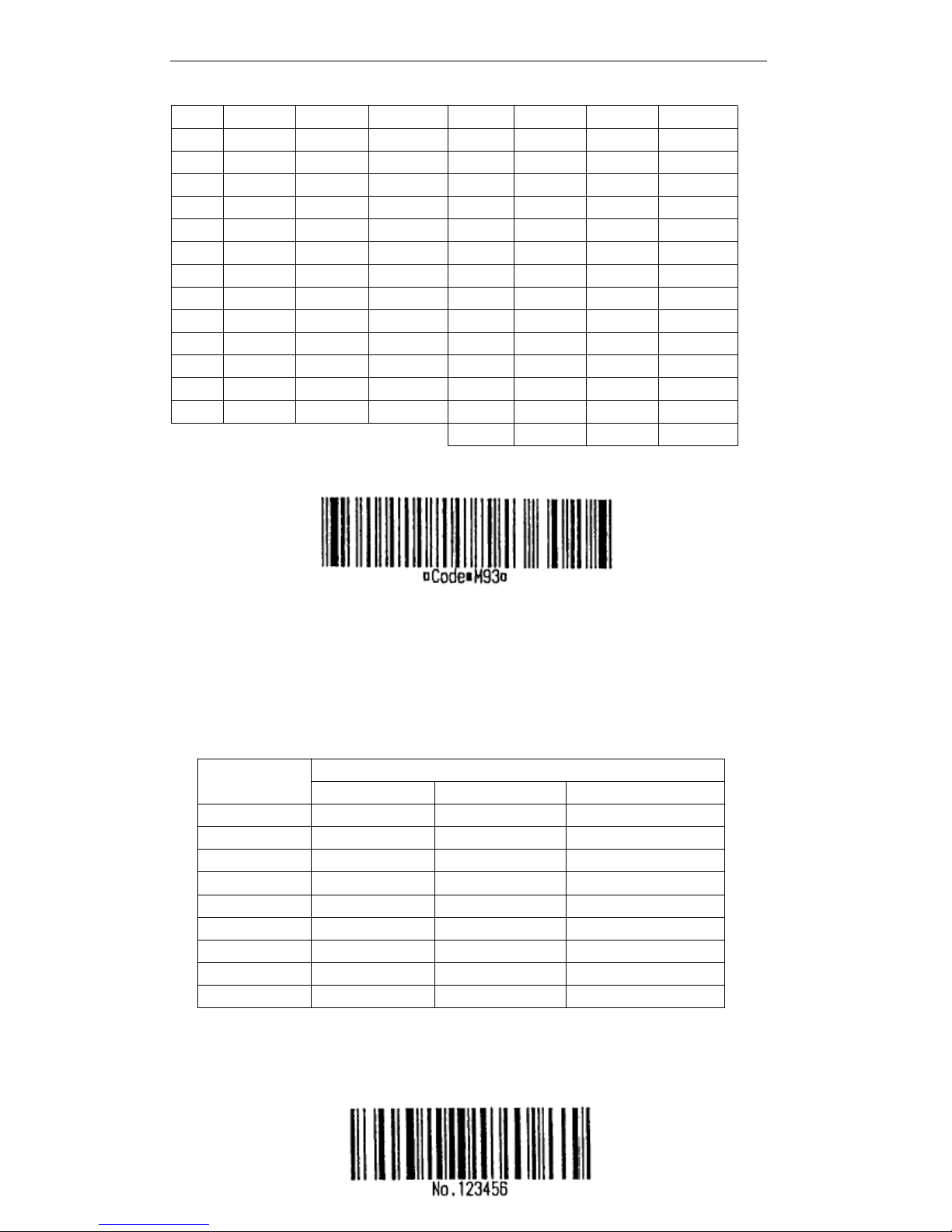
T90 User Manual
75
[For example] Print GS k 72 7 67 111 100 101 13 57 51
When using CODE128 ( m = 73) :
.
Refer to the information of CODE128 bar code and its code table, see the appendix E.
.When the printer uses CODE128, please considers the following data transmission:
①
The head of bar code data font have to the code font select characters (CODE A,
CODE B, or CODE C), be used to select the first used code font.
② Define the special characters by character “ { ” and one character group. Define
ASCII character “ { ” through continuing to transmit “ { ” twice.
[For example] Print "No. 123456" data
As this sample, the printer prints “ No ” by CODE B firstly, then printing the following
numbers by CODE C.
GS
GS
GS
GS k
k
k
k 73 10 123 66 78 111 46 123 67 12 34 56
STX022
■ B
DC21218
■ R
ETX033
■ C
DC31319
■ S
EOT044
■ D
DC41420
■ T
ENQ055
■ E
NAK1521
■ U
ACK066
■ F
SYN1622
■ V
BEL077
■ G
ETB1723
■ W
BS088
■ H
CAN1824
■ XHT099■ IEN1925■ Y
LF0A10
■ J
SUB1A26
■ ZVT0B11■ K
ESC1B27
■ AFF0C12■ LFS1C28■ BCR0D13■ MGS1D29■ C
SO0E14
■ NRS1E30■ DSI0F15■ OUS1F31■ E
DEL7F127
■ T
Special
Character
Transmission Data
ASCII
Hex
Decimal
SHIFT{S7B,53
123,83
CODE A{A7B,41
123,65
CODE B{B7B,42
123,66
CODE C{C7B,43
123,67
FNC1{17B,31
123,49
FNC2{27B,32
123,50
FNC3{37B,33
123,51
FNC4{47B,34
123,52
“ { ”{{7B,7B
123,123
Page 82

T90 User Manual
76
.If the head of bar code data
is
not the code font selected characters, the printer stops processing the
command, and deals with the continued data as the normal data.
.If “ { ” and continued character group are not meet to any special characters, the printer stops processing
the command, and deals with the continued data as the normal data.
.If the printer received the characters which can ’tbe used to special code font, the printer stops
processing the command, and deals with the continued data as the normal data.
.The printer doesn ’tprint the HRI characters which relative to shift characters or code font selected
characters.
.Related function HRI characers are blank.
.Related control characters (<00>H to <1F>H and HRI characters <7F>H) are blank.
<Anothers> Be sure to leave the spacing both on right and left bar code. (the different bar code
type, the different spacing)
[Reference] GS
GS
GS
GS H
H
H
H , GS
GS
GS
GS f
f
f
f , GS
GS
GS
GS h
h
h
h , GS
GS
GS
GS w
w
w
w
GS
GS
GS
GS r
r
r
r n
n
n
n
[Name] Transmit status
[Format] ASCII GS r n
Hex 1D 72 n
Decimal 29 114 n
[Range] n = 1, 49
[Description] Transmit n as follows:
[Notes] .When using serial interface, If set DTR/DSR control, the printer only transmits one byte
after the host have received the date (DSR signalisSPACE). If the host haven ’tready to
receive data (DSR signalisMARK), the printer wait until the host have rea dy to.
If set XON/XOFF control, the printer only transmits one byte, and can not specify the DSR
signal status.
.Execute this command when the data made in the print buffer area. So, between receiving
this command and transmitting status, may be one time spacing,itdecides by the status of
receive buffer area.
.When uses GS a to enable ASB, distinguish the transmitting status by GS r and ASB status
by appendix C.
.Transmitting status type as follows: ·
Roll paper sensor status (n = 1, 49)
N
Function
1,49
Transmit roll paper sensor status
Bit
Off/On
Hex
Decimal
ASB Status
0 , 1
Off000
Roll paper near-end sensor: enough.
On033
Roll paper near-end sensor: end.
2 , 3
Off000
Roll paper end sensor: enough.
Page 83
T90 User Manual
77
Bit 2 and 3: When the roll paper end sensor detects no paper, the printer turns to offline, and
don ’ t execute this command. So, bit 2 and 3 can not transmit no paper status.
[Reference] DLE
DLE
DLE
DLE EOT
EOT
EOT
EOT , GS
GS
GS
GS a
a
a
a
GS
GS
GS
GS v
v
v
v 0
0
0
0 m
m
m
m xL
xL
xL
xL xH
xH
xH
xH yL
yL
yL
yL yH
yH
yH
yH d1
d1
d1
d1 ...
...
...
... dk
dk
dk
dk
[Name] Print grating bit image
[Format] ASCII GS v 0 m xL xH yL yH d1...dk
Hex 1D 76 30 m xL xH yL yH d1...dk
Decimal 29 118 48 m xL xH yL yH d1...dk
[Range] 0 ≤
m ≤ 3, 48 ≤
m ≤
51
0 ≤ xL
≤
255
0 ≤ xH ≤
255 here 1 ≤
(xL + xH ×
256) ≤
128
0 ≤ yL ≤
255
0 ≤ yH ≤
8 here 1 ≤
(yL + yH ×
256) ≤
4095
0 ≤ d ≤ 255
k = (xL + xH × 256) ´ (yL + yH ×
256) (k ≠
0)
[Description] Set grating bit image as follows:
(dpi: per 25.4 mm {1 inch}print dot)
· xL , xH , set bit image horizontal direction data byte (xL+xH × 256).
· yL , yH , set bit image vertical direction data byte (yL+yH × 256).
[Notes] · In standard mode, this command affects only when there are no data in print buffer
area.
· For grating bit image print, this command doesn ’ t affect by print mode (character
size , bold , overlap , upside down print , underline , invert blank print etc. ).
.If the printable area width which set by GS L and GS W
is
narrower than the min width,
the printer only extends the problem line to the min width. The min width for the
normal mode (m=0,48) and the double height mode(m=2, 50) are one dot, for the
double width mode(m=1,49) and the four times mode(m=3,51) are two dots.
.The data out of the print area be read, and discarded one by one.
.
If the continued character position
is
multiple of 8. The continuthe ed character print
position as the grating bit image print, set by HT(horizontal table), ESC $(set absolute
print position), ESC ﹨ (set relative print position) and GS L(set left side s pacing).
.The set by ESC a (set justification) for the grating bit imageisalso effective.
.Receive this command during macro definition, the printer finishes the macro definition,
and begins to execute this command. The definition of this command should be cleared .
· d specifies bit image data. Set the dot which will be printed as 1, the dot which won ’ t
On
( 0C )
( 12 )
Roll paper end sensor: end.
4
Off000
Off is fixed.
5 , 6---Undefined.
7On000Off is fixed.
m
Mode
Vertical dot density
Horizontal dot density
0, 48
Normal
203.2 dpi
203.2 dpi
1, 49
Double width
203.2 dpi
101.6 dpi
2, 50
Double height
101.6 dpi
203.2 dpi
3, 51
Four time size
101.6 dpi
101.6 dpi
Page 84
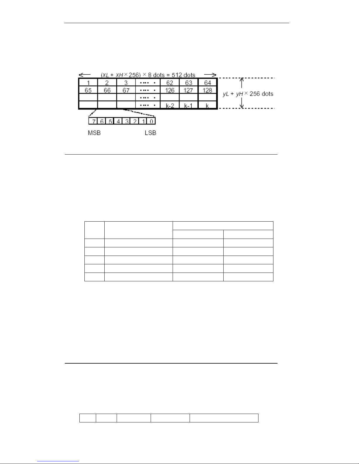
T90 User Manual
78
be printed as 0.
[For example] When xL+xH × 256=64
GS w n
[Name] Set bar code width
[Format] ASCII GS w n
Hex 1D 77 n
Decimal 29 119 n
[Range] 2 ≤ n ≤
6
[Description] Set bar code horizontal size.
n set bar code width as follows:
· Multi bar code as follows:
UPC-A, UPC-E, JAN13 (EAN13), JAN8 (EAN8), CODE93, CODE128
. Binary bar code as follows:
CODE39, ITF, CODABAR
[Default] n = 3
[Reference] GS
GS
GS
GS k
k
k
k
5.5
5.5
5.5
5.5 Chinese
Chinese
Chinese
Chinese C
C
C
C haracter
haracter
haracter
haracter C
C
C
C ontrol
ontrol
ontrol
ontrol C
C
C
C ommand
ommand
ommand
ommand
FS
FS
FS
FS !
!
!
! n
n
n
n
[Name] Set print mode for Chinese character
[Format] ASCII FS ! n
Hex 1C 21 n
Decimal 28 33 n
[Range] 0 ≤ n
≤ 255
[Description] Set print mode for Chinese character, set n as follows:
n
Multi bar code unit
width(mm)
Binary bar code
Narrow width(mm)
Wide width(mm)
2
0.250
0.250
0.62530.375
0.375
1.00040.560
0.500
1.25050.625
0.625
1.625
6
0.750
0.750
2.000
Bit
Off/On
Hex
Decimal
Function
Page 85

T90 User Manual
79
[Particularize] . Set both double width mode and double height mode (contain right side and left
side character spacing), will print four times character size.
.
The printer can add underline to all characters (contain right side and left side
character spacing), but can ’tadd underline to the blank which set by HT command ,
and clockwise 90 ° revolved characters .
· The underline width specified by FS.Itis
not relevant to the character size .
· When some of characters in a line are double height or more times,all characters
in this line will adjust along the base line.
· Bold Chinese character by FS W or GS
!,
the last received setiseffective .
· Set/cancel the underline mode by FS, the last received setiseffective.
[Default] n = 0
[Reference] FS
FS
FS
FS -
-
-
- , FS
FS
FS
FS W
W
W
W , GS
GS
GS
GS !
!
!
!
FS
FS
FS
FS &
&
&
&
[Name] Set Chinese character mode
[Format] ASCII FS &
Hex 1C 26
Decimal 28 38
[Description] Select Chinese character mode.
[Particularize] · This command only affects when selecting GB18030 code system.
· GB18030 only supports double bytes 1 、 2 、 3 、 4 、 5 area.
· Select Chinese character mode, the printer processes all Chinese character code,
two bytes each time.
· Process Chinese character code as the sequence of the first byte, the second byte.
· Turn the power on, the printer enter into Chinese character mode automatically.
· Select Chinese character mode, firstly the printer detects whether the code
is
Chinese character or not; Ifitis
the Chinese character and processes the first byte
and the second byte.
[Reference] FS
FS
FS
FS .
.
.
. , FS
FS
FS
FS C
C
C
C
FS
FS
FS
FS –
–
–
– n
n
n
n
[Name] Turn underline mode on/off for Chinese characters
[Format] ASCII FS - n
Hex 1C 2D n
0
---
Undefined1---
Undefined
2
Off000
Disable double width mode
On044
Enable double width mode
3
Off00.
Disable double height mode
On088
Disable double height mode
4
---
Undefined5---
Undefined
6
---
Undefined
7
Off000
Disable underline mode
On08128
Enable underline mode
Page 86

T90 User Manual
80
Decimal 28 45 n
[Range] 0 ≤ n ≤
2, 48 ≤ n ≤
50
[Description] For receipt and allonge, turn underline mode on/off for Chinese characters as follows:
[Particularize]
.
The printer can add underline to all characters(contain right side and left side
character spacing), but can ’tadd underline to the blank which set by HT command,
and clockwise 90 ° revolved characters.
.
Set n as0,and turn underline off for Chinese characters, won ’texecute unterline print ,
but the underline width set before which remains the same. Default underline width
is
1 dot.
.
Even the character sizeischanged, the specified underline width remains the same.
.
Turn underline mode on/off by FS
!,
and the last received commandiseffective.
.
Select allonge, even nis2 or 50, the underline width
is
1 dot.
[Default] n = 0
[Reference] FS
FS
FS
FS !
!
!
!
FS
FS
FS
FS .
.
.
.
[Name] Cancel Chinese mode
[Format] ASCII FS .
Hex 1C 2E
Decimal 28 46
[Description] Cancel Chinese mode
[Particularize] · This command only affects when selecting GB18030 code system.
· When Chinese character mode doesn ’tbe selected, all character codes are ASCII
code, process one character each time.
· Turn the power on, the printer enters into Chinese character mode automatically.
[Reference] FS
FS
FS
FS &
&
&
& , FS
FS
FS
FS C
C
C
C
FS
FS
FS
FS 2
2
2
2 [c11
[c11
[c11
[c11 c12
c12
c12
c12 d1...d1k]1
d1...d1k]1
d1...d1k]1
d1...d1k]1 …
…
…
… [cn1
[cn1
[cn1
[cn1 cn2
cn2
cn2
cn2 d1...dnk]n
d1...dnk]n
d1...dnk]n
d1...dnk]n NULL
NULL
NULL
NULL
[Name] Define user-defined Chinese character
[Format] ASCII FS 2 [c11 c12 d1...d1k]1 … [cn1 cn2 d1...dnk]n NUL
Hex 1C 32 [c11 c12 d1...d1k]1 … [cn1 cn2 d1...dnk]n 00
Decimal 28 50 [c11 c12 d1...d1k]1 … [cn1 cn2 d1...dnk]n 0
[Range] c1, c2 are zone bit codes in the user-defined Chinese character which set by FS
2,
K=72, n
is
the number of Chinese character which will be defined, d1 … dk are defined
Chinese character data. Another zone bit codes which are not in the selected user-
defin ed Chinese character zone, will be no any meanings.
[Description] · c1
is
zone code 、 c2
is
bit code. User-defined Chinese character saved in FLASH,
lost when turn the power off.
.Before defining user-defined Chinese character by FS 2 command, have to make
sure the used code zone. (use FS C command, more details refer to FS C
command description.)
n
Function
0, 48
Turn underline mode off for Chinese characters
1, 49
Turn underline mode on for Chinese characters(1 dot width)
2, 50
Turn underline mode on for Chinese characters(2 dots width)
Page 87
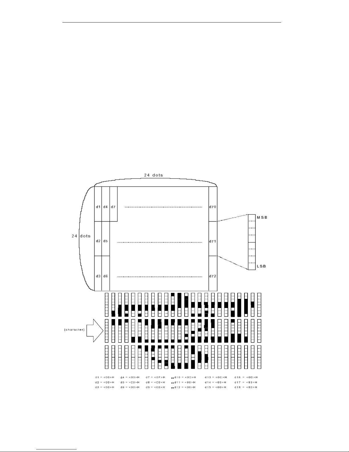
T90 User Manual
81
.After transmitting FS 2 [c11 c12 d1...d1k]1...[cn1 cn2 d1...dnk]n, finishes
definition by transmitting NUL finally.
· After sending FS 2 [c11 c12 d1...d1k]1 … [cn1 cn2 d1...dnk]n , at last send
NUL to finish the definition.
.Repeat [note] to define the character frequently,Itmay break FLASH MEMORY , so
suggests thatitis
less than ten times every day.
.Define several Chinese characters, finish by one command as makes definition
together.
· This command affect onlyatthe origin of one line.
[Particularize] This command can define n characters each time, after sending FS 2 [c11 c12
d1...d1k]1...[cn1 cn2 d1...dnk]n, to end the definition by sending NUL
at
last. You
can define all Chinese characters in the the user-defined zone according to this
command. Re peat to define, as more two times.
[Default] Blank
[Reference] FS
FS
FS
FS C
C
C
C
[For example]
FS
FS
FS
FS C
C
C
C n
n
n
n
[Name] Select Chinese character code system
[Format] ASCII FS C n
Hex 1C 43 n
Page 88

T90 User Manual
82
Decimal 28 67 n
[Range] n = 0 、 1 、 2 、 48 、 49 、 50
[Description]
Notes : 1 、 Change user zone,will clear all old characters.
2 、 Use user defined Chinese characters, notes that selected zone the same as defined
zone,
Or, Or,
may print incorrectly.
3 、 Before defining by FS
2,
be sure user defined zone by FS C firstly.
[Default] n = 0
FS
FS
FS
FS S
S
S
S n
n
n
n 1
1
1
1 n
n
n
n 2
2
2
2
[Name] Set Chinese character spacing
[Format] ASCII FS S n1 n2
Hex 1C 53 n1 n2
Decimal 28 83 n1 n2
[Range] 0 ≤
n1 ≤ 2 55
0
≤ n2 ≤
255
[Description] Set Chinese character spacing n1 and n2 separately.
· Left Chinese character spacing is [ n1 × 0.125 mm ], Right Chinese character spacing
is [ n2 ×
0.125 mm ] .
[Particularize] .This command set left side and right side Chinese characters spacing in normal size.
When setting double width mode, left side and right side Chinese characters spacing
are twice than normal mode.
.Set spacing by this command separately in standard mode and page mode.
· In standard mode, use horizontal motor unit.
· In page mode, Horizontal motor unit or vertical motor unitisdifferent according to pge
mode, deponds on the origin print position. More as follows:
① set the origin position to the up-left or down-right of printable area by ESC
T,
use the horizontal motor unit(x).
② Set the origin position to the up-right or down-left of printable area,use the
vertical motor unit(y).
③ For allonge, the max right side spacing
is
about 32 ㎜ (255 × 0.125 ㎜ ). Any set
which overs the max will be changed to the max data automatically.
[Default] n1 = 0, n2 = 0
FS
FS
FS
FS W
W
W
W n
n
n
n
[Name] Turn quadruple-size mode on/off for Chinese characters
[Format] ASCII FS W n
Hex 1C 57 n
Decimal 28 87 n
[Range] 0
≤ n ≤ 255
N
User defined zone
Code bit range
0 , 48
User zone 1
AAA1 ~ AFFE
1 , 49
User zone 2
F8A1 ~ FEFE
2 , 50
User zone 3
A140 ~ A7A0
Page 89

T90 User Manual
83
[Description] Turn quadruple-size mode on/off for Chinese characters.
· When the LSB is 0, turn quadruple-size mode off for Chinese characters.
· When the LSB is 1, turn quadruple-size mode on for Chinese character.
[Particularize] .Only LSB of niseffective.
.In quadruple-size mode, the print character size
is
the same as the print character
size which be set double width and double height .
· Turn quadruple-size mode off by this command, the following character size printed
as normal size.
.Different character height in one line, all characters in this line will be adjusted on base
line.
.Characters enlarges along the horizontal direction, characters enlarges to the right
side on basis of the left side.
.Select double width and double height mode, turn quadruple-size mode on/off by FS !
or GS !. The last received command setiseffective.
[Default] n = 0
[Reference] FS
FS
FS
FS ! , GS
GS
GS
GS !
APPENDIX
APPENDIX
APPENDIX
APPENDIX A:
A:
A:
A: MISCELLANEOUS
MISCELLANEOUS
MISCELLANEOUS
MISCELLANEOUS NOTES
NOTES
NOTES
NOTES
A.1
A.1
A.1
A.1 Print
Print
Print
Print and
and
and
and feed
feed
feed
feed paper
paper
paper
paper notes
notes
notes
notes
1) The printer is the line printer, so auto cut after printing. So, When the line spacing is less than
print data, the feed paper quantity may be more than set feed paper quantity and to print data.
For example, the line spacing is 10 dots (10/180 inch), only execute feed paper, roll paper fed 10
dots, If print the bit image characters, the printer feeds paper 24 dots.
Only print character rotation in one line, execute feed paper as the table A.
2) When the printer enters into ready mode (data ready) during print period, so stops printing and
feeding paper for a while. When execute data transmission and printing, roll paper will be
moved 1 to 3 dots from origin position,itaffects bit image printin g mainly.
3) In receipt parts, auto cut operated spacing
For auto cutter in driver receipt parts, the min spacing
is
10 print line or feed paper line (prevent
the small sheet paper to auto cut).
A.2
A.2
A.2
A.2 External
External
External
External Power
Power
Power
Power Connection
Connection
Connection
Connection Notes
Notes
Notes
Notes
· Connect the external power to the printer. and turn the power on when need. Be sure the
correct connection, if it is wrong, may be damage the external power or the printer.
Paper feed quantity ( dot )
Normal
character
Font A
24 Χ vertical magnification
Font B
17 Χ vertical magnification
Chinese characters
24 Χ vertical magnification
Character
rotation
Font A
12 Χ vertical magnification
Font B
9 Χ vertical magnification
Chinese characters
24 Χ vertical magnification
Bit image ( ESC* )
24
Page 90

T90 User Manual
84
· Over high voltage or low voltage occurred, turn the power off as soon as possible.
A.3
A.3
A.3
A.3 Another
Another
Another
Another Notes
Notes
Notes
Notes
The printer operation
When roll paper cover is closed, do not pull the roll paper.
Thermal print head slice and driver IC are easy to damage, do not touch by
metal.
In printing process or after using one period time, thermal print head slice
temperature turns to high, do not touch the print head slice.
Do not use the roll paper cover usually when it is with roll paper.
Do not touc the print head slice, dusty and other dirt materials with print head
cover that will damage the print head.
Thermal roll paper contains Na+, K+, Cl- that will damage the thermal
element with thermal print head, so, please use the specified roll paper.
Label paper can not be used.
APPENDIX
APPENDIX
APPENDIX
APPENDIX B:
B:
B:
B: ROLL
ROLL
ROLL
ROLL PAPER
PAPER
PAPER
PAPER SETUP
SETUP
SETUP
SETUP
B1
B1
B1
B1 Change
Change
Change
Change roll
roll
roll
roll paper
paper
paper
paper
1 、 Open the roll paper cover.
2 、 Put the new roll paper.
3 、 Pull one small part, and close the roll paper cover.
APPENDIX
APPENDIX
APPENDIX
APPENDIX C
C
C
C :
:
:
: GET
GET
GET
GET RIGHT
RIGHT
RIGHT
RIGHT FROM
FROM
FROM
FROM AUTOCUTTER
AUTOCUTTER
AUTOCUTTER
AUTOCUTTER ERROR
ERROR
ERROR
ERROR
If the other materials, as clip, fall to autocutter and lock up autocutter, the printer turn to error status
and recover operation automatically.
If the problem is not serious, autocutter recovers to the normal position automatically. (Error LED
flash continuely, but error may be correct automatically.)
If autocutter does not return to the normal position, so run autocutter motor to return the origin
position.
If can not run motor geer, so contrarotate to loosen gear; then push feed paper button. Next, detect
error LED, If error LED always flash, repeat the same step, until turn error LED off. When turning
error LED off, autocutter cut returned to normal positi on. Open the cover, move the jammed paper,
put the roll paper again. A t last, close the cover.
APPENDIX
APPENDIX
APPENDIX
APPENDIX D:
D:
D:
D: CLEAN
CLEAN
CLEAN
CLEAN THE
THE
THE
THE PRINT
PRINT
PRINT
PRINT HEAD
HEAD
HEAD
HEAD
Roll paper slice fallen to the print head, it will cause print quality, clean the print head as the
following steps:
1. Turn the power off, and pull the power cable and communication out.
2. Open the roll paper cover.
Page 91
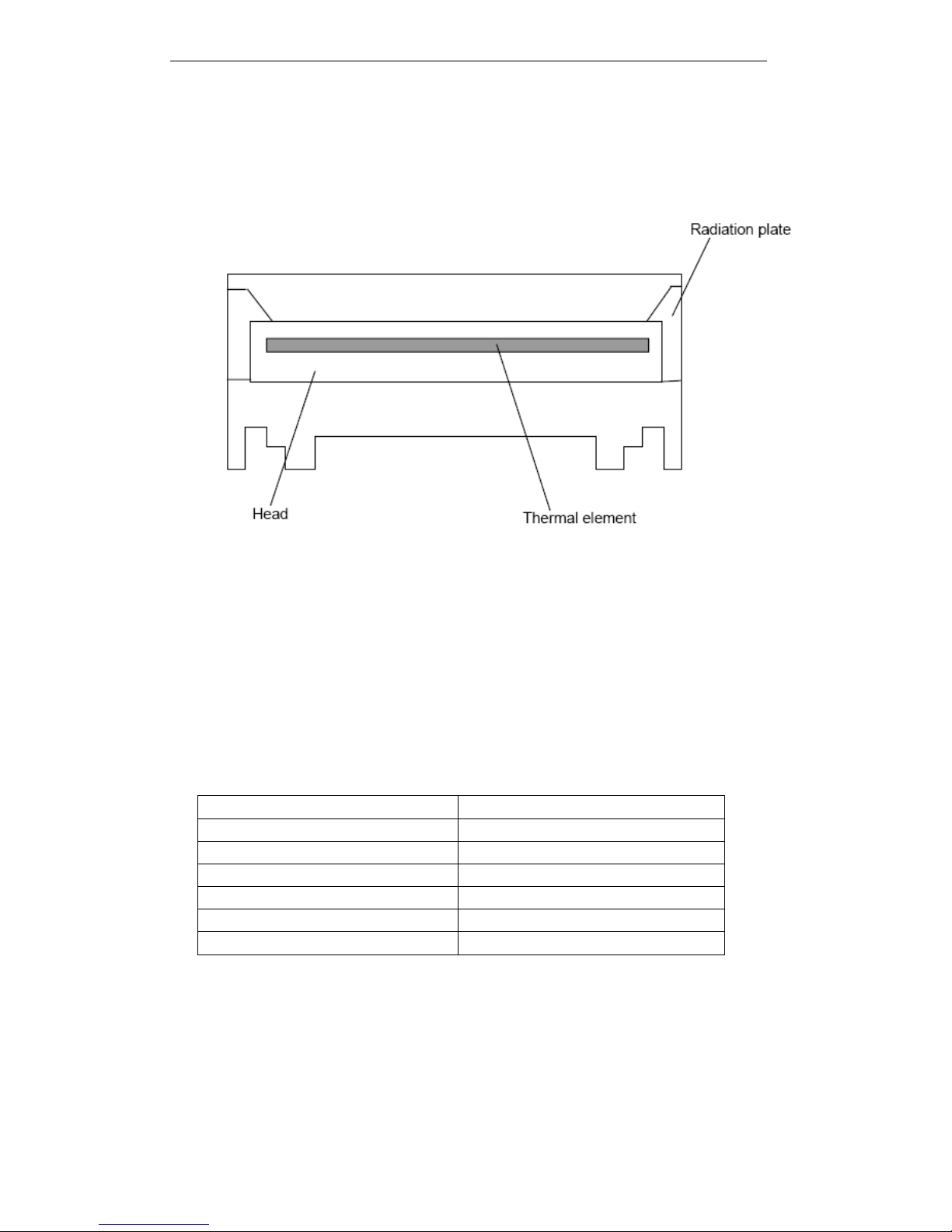
T90 User Manual
85
3. Clean cotton with a little alcohol, paint to surface dirt slightly, do not use sandpaper, blade or
force materials to clean print head slice! Or, the thermal print head slice will be damaged,
and can not be recovered.
4. Clean the print head slice, after complete dry, do self test, watch the print result.
Note
Note
Note
Note : Never clean the print head slice when the thermal print head slice
is
heat,
Or,itwill cause head
slice to break.
APPENDIX
APPENDIX
APPENDIX
APPENDIX E:
E:
E:
E: THE
THE
THE
THE MARK
MARK
MARK
MARK OF
OF
OF
OF TRANSFER
TRANSFER
TRANSFER
TRANSFER STATUS
STATUS
STATUS
STATUS
Because the specific transmission status bit from this circuit board
is
fixed, the user can confirm the
command of status:
Table C.1 Transmission status sign
APPENDIX
APPENDIX
APPENDIX
APPENDIX F:
F:
F:
F: THE
THE
THE
THE EXAMPLE
EXAMPLE
EXAMPLE
EXAMPLE OF
OF
OF
OF PAGE
PAGE
PAGE
PAGE MODE
MODE
MODE
MODE
In page mode, transmission command process as follows:
① Enter into page mode by ESC L.
Command and function
Respond status
GS r
〈 0**0**** 〉 B
XON
〈 00010001 〉 B
XOFF
〈 00010011 〉 B
DLE EOT
〈 0**1**10 〉 B
ASB(1stbyte)
〈 0**1**00 〉 B
ASB(2ndto 4thbytes)
〈 0**0**** 〉 B
Page 92
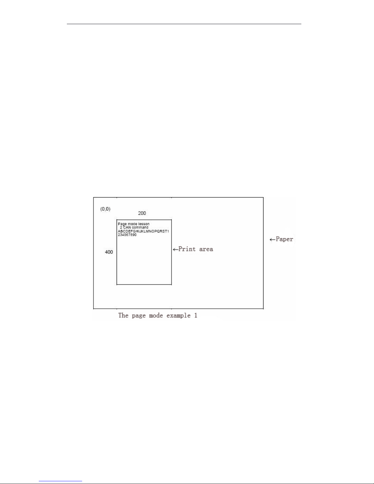
T90 User Manual
86
② Specify print area by ESC W.
③ Specify print direction by ESC T.
④ Transmit print data.
⑤ Put data together by FF.
⑥ The printer automatically returns to standard mode after printing
For example 1 : BASIC program example(if #1 file opened , can be transmitted data
totheprinter)
100 PRINT #1,CHR$(&H1B);"L";
110 PRINT #1,CHR$(&H1B);"W";CHR$(0);CHR$(0);CHR$(0);CHR$(0);
120 PRINT #1,CHR$(200);CHR$(0);CHR$(144);CHR$(1);
130 PRINT #1,CHR$(&H1B);"T";CHR$(0);
140 PRINT #1,"Page mode lesson TEST 1"
150 PRINT #1,CHR$(&HC);
In example 1 program, set one print area from (0,0) 200 ´ 400 dots , and print charactersat
the first line, as follow s :
Note : Insert one feed paper line between "lesson" and "TEST 1". Because in the 200 ´ 400 print area
horizontal range, behind word "lesson" no empty mark “” position , so insert this feed paper line
automatically. Feed paper quantity set by ESC 3. Before execu ting FF , can set any quantity
print area. If any print area is overlapping, the overlapping data part to print as the last data.
The generated data could be deleted partly. Specify one print area by ESC
W,
this area make up
the deleted part. All data in specified area will be deleted, even its only part of characters.
Example 2: BASIC program example
100 PRINT #1,CHR$(&H1B);"L";
110 PRINT #1,CHR$(&H1B);"W";CHR$(0);CHR$(0);CHR$(0);CHR$(0);
120 PRINT #1,CHR$(200);CHR$(0);CHR$(144);CHR$(1);
130 PRINT #1,CHR$(&H1B);"T";CHR$(0);
Page 93
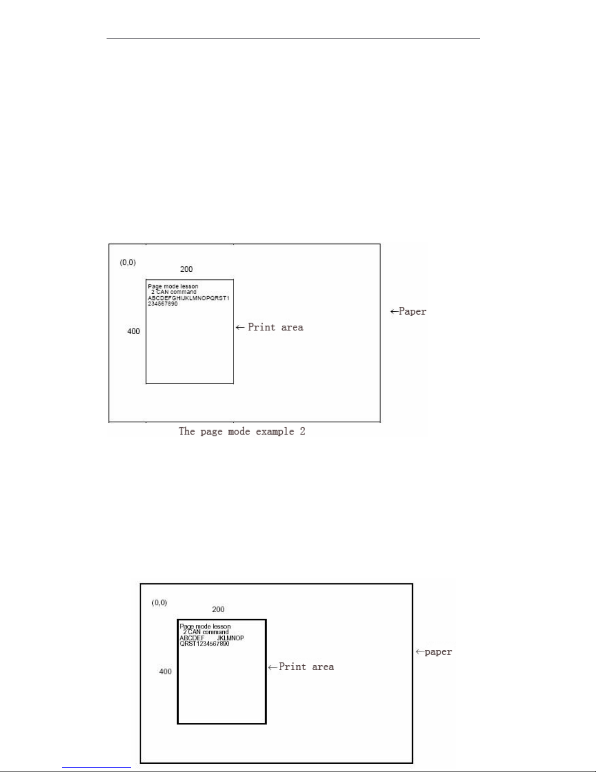
T90 User Manual
87
140 PRINT #1,"Page mode lesson 2 CAN command"
150 PRINT #1,CHR$(&HA);
160 PRINT #1,"ABCDEFGHIJKLMNOPQRST1234567890"
170 PRINT #1,CHR$(&HC);
The process as follows :
Firstly , transmit ESC L to turn to page mode ( 100 lines ) . Then sending n1 to n8 by ESC W
a ccording to the specified print area. Specify one print area from (0,0) , 200 dots in x direction , 400
dots in y direction. Send parameter as 0,0,0,0,200,0,144,1(line number 110 and 120). In
addition, set print direction to 0 by ESC T (line number 130).
After setting these items, transmit print data “ Page mode lesson 2 CAN command ” and
“ ABCDEFGHIJKLMNOPQRST1234567890 ” (line number 140 to 160). The following print result by
sending FF (line number 170).
Contain the following program line by sending FF, the part data will be deleted:
170 PRINT #1,CHR$(&H1B);"W";CHR$(72);CHR$(0);CHR$(96);CHR$(0);
180 PRINT #1,CHR$(51);CHR$(0);CHR$(81);CHR$(0);
190 PRINT #1,CHR$(&H18);
200 PRINT #1,CHR$(&HC);
Contain the above program, delete character “ GHI ” series, will bring to the following print result.When
deleting one area by CAN, the blank as the deleted part.
The page mode example 3
Page 94

T90 User Manual
88
APPENDIX
APPENDIX
APPENDIX
APPENDIX G:
G:
G:
G: CODE128
CODE128
CODE128
CODE128 BAR
BAR
BAR
BAR CODE
CODE
CODE
CODE
G.1
G.1
G.1
G.1 CODE128
CODE128
CODE128
CODE128 bar
bar
bar
bar code
code
code
code description
description
description
description
In CODE128 bar code system, use one bar code character set , indicate 128 unit ASCII
charactersand 2 bit data. These bar code characters specif y 103 unit bar code characters and 3
unit code. Each code indicates the following characters:
· Code set A : ASCII character from 00H to 5FH
· Code set B : ASCII character from 20H to 7FH
· Code set C: 2 bit natural digit character indicate by one character (100 unit natural digit from
00 to 99)
The following special characters in CODE128 :
· SHIFT characters
Code set A , the code follow with SHIFT will be processed as code B. Code B, the code
followwith SHIFT will be processed as code A. SHIFT characters can not be used in code C.
· Code set select character (CODE A, CODE B, CODE C)
The code set follow with this character turn to code AB or C.
· Function characters (FNC1, FNC2, FNC3, FNC4)
Function character depends on application software. FNC1 is valid in code C.
G.2
G.2
G.2
G.2 Code
Code
Code
Code table
table
table
table
Printable
Printable
Printable
Printable character
character
character
character in
in
in
in code
code
code
code set
set
set
set A
A
A
A
Character
Transmit Data
Character
Transmit Data
Character
Transmit Data
Hex
Decimal
Hex
Decimal
Hex
Decimal
NUL000(2840P5080
SOH011)2941Q5181
STX022*2A42R5282
ETX033+2B43S5383
EOT044,2C44T5484
ENQ055-2D45U5585
ACK066.2E46V5686
BEL077/2F47W5787BS08803048X5888T09913149Y5989
LF0A1023250Z5A90VT0B1133351[5B
91
FF0C1243452\5C92CR0D1353553]5D93SO0E1463654^5E94SI0F1573755_5F
95
DLE101683856FNC1
7B, 31
123,49
DC1111793957FNC2
7B,32
123,50
DC21218:3A58FNC3
7B,33
123,51
DC31319;3B59FNC4
7B,34
123,52
DC41420<3C60SHIFT
7B,53
123,83
NAK1521=3D61CODEB
7B,42
123,66
Page 95
T90 User Manual
89
Printable
Printable
Printable
Printable character
character
character
character in
in
in
in code
code
code
code set
set
set
set B
B
B
B
SYN1622>3E62CODEC
7B,43
123,67
ETB1723?3F
63
CAN1824@4064EM1925A4165SUB1A26B4266ESC1B27C43
67
FS1C28D4468GS1D29E45
69
RS1E30F4670US1F31G4771SP2032H4872!2133I49
73
"2234J4A74#2335K4B
75
$2436L4C76%2537M4D77&2638N4E
78
'2739O4F79Character
Transmit Data
Character
Transmit Data
Character
Transmit Data
Hex
Decimal
Hex
Decimal
Hex
Decimal
SP2032H4872p70112!2133I4973q71
113"2234J4A74r72
114
#2335K4B75s73115$2436L4C76t74
116
%2537M4D77u75117&2638N4E78V76
118'2739O4F79w77
119(2840P5080x78
120
)2941Q5181y79121*2A42R5282z7A
122
+2B43S5383{
7B,7B
123,123,2C44T5484|7C
124_2D45U5585}7D
125.2E46V5686—7E
126
/2F47W5787DEL7F12703048X5888
FNC1
7B,31
123,49
13149Y5989FNC2
7B,32
123,5023250Z5A90
FNC3
7B,33
123,5133351[5B91
FNC4
7B,34
123,5243452\5C92
SHIFT
7B,53
123,83
53553]5D93CODEA
7B,41
123,6663654^5E94
CODEC
7B,43
123,67
Page 96
T90 User Manual
90
Printable
Printable
Printable
Printable character
character
character
character in
in
in
in code
code
code
code set
set
set
set C
C
C
C
73755_5F9583856`60
96
93957a6197:3A58b6298;3B59c6399<3C60d64
100
=3D61e65
101>3E62f66102
?3F63g67
103@4064h68104A4165i69105B4266j6A106
C4367k6B
107D4468l6C108
E4569m6D
109F4670n6E110
G4771o6F
111
Character
Transmit Data
Character
Transmit Data
Character
Transmit Data
Hex
Decimal
Hex
Decima
l
Hex
Decimal
000004028408050800101141294181518102022422A42825282
03033432B4383538304044442C4484548405055452D45855585
06066462E4686568607077472F4787578708088483048885888
09099493149895989100A10503250905A90110B11513351915B91
120C12523452925C92130D13533553935D93140E14543654945E94
150F15553755955F95161016563856966096171117573957976197
181218583A58986298191319593B59996399201420603C60FNC1
7B,31
123,49
211521613D61CODEA
7B,41
123,65221622623E62
CODEB
7B,42
123,66
Page 97

T90 User Manual
91
231723633F632418246440
64
251925654165261A26664266271B27674367281C286844
68
291D29694569301E307046
70
311F31714771322032724872332133734973342234744A
74
352335754B75362436764C
76
372537774D77382638784E
78
392739794F
79
 Loading...