

Page 1
LEM
SURE-LITES
page 1
Installation Instructions for the Sure-Lites LEM Emergency Light
IMPORTANT SAFEGUARDS
WHEN USING ELECTRICAL EQUIPMENT, BASIC SAFETY PRECAUTIONS SHOULD
ALWAYS BE OBSERVED INCLUDING THE FOLLOWING
1. READ AND FOLLOW ALL SAFETY INSTRUCTIONS
2. 2. Do not use outdoors.
3. Do not use in hazardous locations, or near gas or electric heaters.
4. Do not let power supply cords touch hot surfaces.
5. Do not use this equipment for other than the intended use.
6. Installation is to be performed only by qualified personnel.
7. Install in accordance with National Electric Code and local regulatory agency requirements.
8. The use of accessory equipment not recommended by the manufacturer may cause an
unsafe condition.
9. Equipment should be mounted in locations and at heights where it will not readily be subjected to tampering by
unauthorized personnel.
10. SAVE THESE INSTRUCTIONS
Risk of Fire/Electric
Shock
If not qualified, consult an
electrician.
INSTALLATION
Step 1 De-energize the circuit at the junction box (J-box) where the emergency light is to be installed.
Step 2 Open the emergency light by inserting a screwdriver in the two slots at the bottom of the unit, then
tipping the cover up off of the backplate.
Step 3 To mount to a junction box - Drill out the appropriate mounting pattern and the wire pass hole in
the backplate to fit the J-box being used.
Step 4 To mount to conduit – Cut out the U shaped knockout on the cover using snips, then attach the
½” conduit hub to the backplate
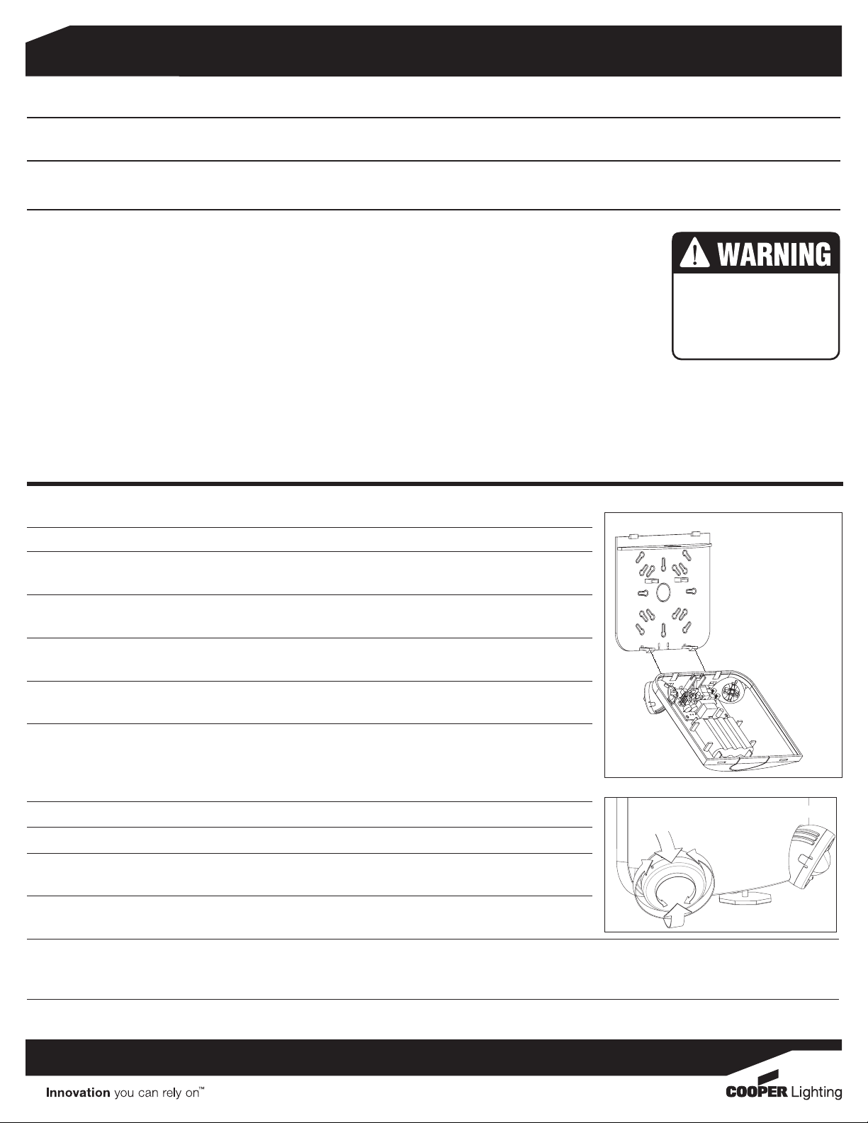
Step 5 Once the backplate is secured, the housing can be held in place during installation using the EZ
Hang feature. (see Fig. 1)
Step 6 Connect the incoming wires to the LEM power supply wires using the wire nuts provided.
Connect the white wire to neutral. If using 120V, connect the black wire to the hot lead. If using
277V, connect the orange wire to the hot lead. Cap the unused lead. Secure the emergency light
to the wall and/or junction box using installer supplied hardware.
Step 7 Snap the cover onto the backplate.
Step 8 Remove the EZ key battery disconnect.
Step 9 Energize AC supply. The test button should illuminate, and LED heads will illuminate briefly when
the test button is pushed.
Step 10 Adjust the heads as needed. The LEM heads utilize a highly directional beam, so the head is
adjustable in 3 axes, not the usual 2. (see Fig. 2)
Figure 1
Slide snaps
through holes
in housing for
temporary mount
when wiring
Figure 2
Step 11 If the LEM is to be powered down for an extended period after initial installation, replace the EZ Key. This will prevent the battery from discharging
when AC power is removed. However, it will also prevent the battery from charging when AC power is restored, so it must be removed once the
unit is ready for regular operation.
Page 2
LEM
SURE-LITES
OPERATION
Depress the test switch. The LED heads will light and the charge LED will extinguish. LED heads will illuminate as long as the button is
pushed. Release the test switch. The charge LED will illuminate and the LED heads will turn off.
MAINTENANCE: None required. Replace the batteries as needed according to ambient conditions. However, we recommend that the
equipment be tested regularly in accordance with local codes.
NOTE: Servicing of any parts should be performed by qualified personnel. Only use replacement parts supplied by Cooper Lighting.
CAUTION: This equipment is furnished with a sophisticated low voltage battery dropout circuit to protect the battery from over discharge after its
useful output has been used. Allow 24 hours recharge time after installation or power failure for 90 minute testing.
TROUBLE SHOOTING GUIDE
If LED heads or charge indicator LED does not illuminate, check the following:
1. Check AC supply – verify that unit has 24 hour AC supply.
2. Unit is shorted or battery is not connected.
3. Battery discharged. Permit unit to charge for 24 hours and then re-test.
4. If following the above trouble shooting hints does not solve your problem, contact your local Cooper Lighting representative for assistance.
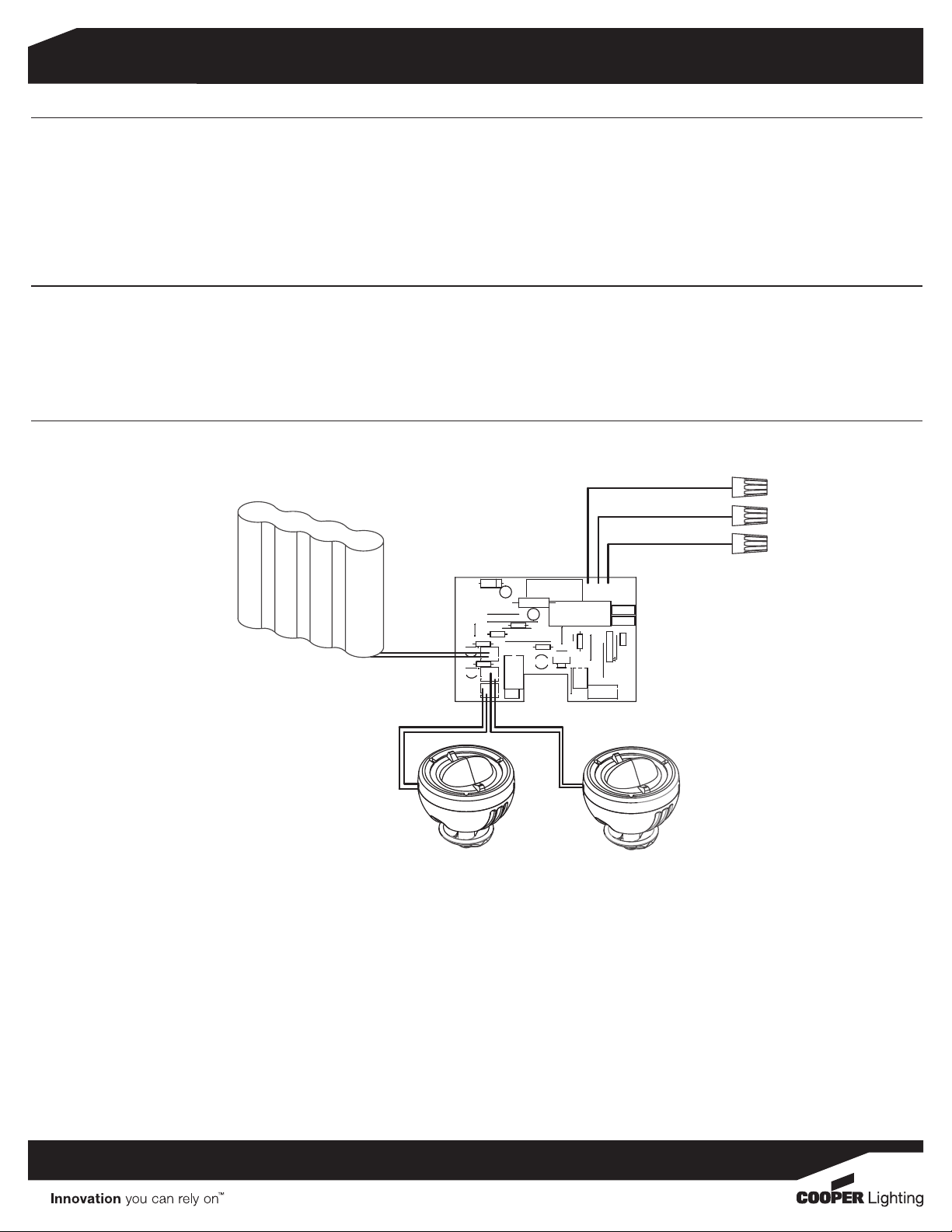
SCHEMATIC
ORANGE LEAD - TO 277V
page 2
BATTERY
CHARGER/DRIVER PCB
D5
c
JMP5
R15
JMP4
R7
Q5
R18
Q1
LAMPS
BLACK LEAD - TO 120V
WHITE LEAD - TO NEUTRAL
N
277
+
C6
F1
C9
+
JMP13
C8
R10
C7
JMP6
JMP7
R30
BATT
LED1
JK1
SW1
120
MOV1
MOV2
CN4
JMP8
JMP9
JMP14
PR1
J1
R13
TDI
JMP10
JMP12
ICSP
JMP11
CN5
LED/SW
LED HEADS
Cooper Lighitng
1121 Highway 74 South
Peachtree City, GA 30269
770.486.4800 Fax: 770.486.4801
7/20/12 049-220
 Loading...