

Page 1
ADX142715
EBP1400NCX and EBP1400NCF Instruction Manual
Brand Logo
reversed out of
black
INS #
INS #
WARNING
Risk of Fire/Electric Shock
If not qualified, consult an electrician.
EBP1400NCX EBP1400NCF
Important Safeguards
WHEN USING ELECTRICAL EQUIPMENT, BASIC
SAFETY PRECAUTIONS SHOULD ALWAYS BE
OBSERVED INCLUDING THE FOLLOWING.
1. READ AND FOLLOW ALL SAFETY INSTRUCTIONS
2. Do not use outdoors.
3. Do not mount near gas or electric heaters.
4. Equipment should be mounted in locations and
at heights where it will not readily be subject to
tampering by unauthorized personnel.
5. The use of accessory equipment not recommended
by Sure-Lites may cause an unsafe condition.
6. Do not use this equipment for other than its
intended purpose.
7. SAVE THESE INSTRUCTIONS
WARNING
Risk of Electric Shock
Disconnect power at fuse or circuit breaker before
installing or servicing.
For use in temperature rating
CONTAINS NICKEL-CADMIUM
RECHARGEABLEBATTERY.
MUST BE RECYCLEDOR
DISPOSED OF PROPERLY.
NOTES:
Note 1. To prevent high voltage from being present on
the output terminals (red/white, red, and yellow), do
not connect the test button indicator light to the EBP
until Step 7 of the installation instructions.
Note 2. This product is for use with most 2’ through
8’ (6W-215W single and bi-pin fluorescent lamps
including energy saving, circline, U-shaped and biax.
For specific lamp compatibility, please see the table
later in the instructions.
Note 3. Make sure all of the connections are in
accordance with the National Electrical Code and any
local regulations.
Note 4. To reduce the risk of electrical shock,
disconnect both normal and emergency power
supplies and the test button indicator light (which
disconnects the battery) before servicing.
Note 5. This emergency ballast is for factory or field
installation in the ballast channel.
Note 6. This product is for use in indoor fixtures. This
product is not intended for use near air handling
heated air outlets or in wet or hazardous locations.
Note 7. An unswitched AC power source is required
(120, 240, or 277 volts).
Note 8. Do not attempt to service the battery. A sealed,
no-maintenance battery is used that is not field
replaceable. Contact the manufacturer for information
on service.
Note 9. Servicing should be performed by qualified
service personnel.
20°C to 55°C
Ni -Cd
Page 2
EBP1400NCX and EBP1400NCF Instruction Manual
Emergency
Channel
INSTALLATION
WARNING: to prevent high voltage on Red / White, Red,
and Yellow output terminals prior to installation, the Test
Button / Indicator Light must be disconnected. Connect
the Test Button / Indicator Light after installation.
NOTE: Make sure that the necessary branch circuit
wiring is available. An unswitched source of power is
required.
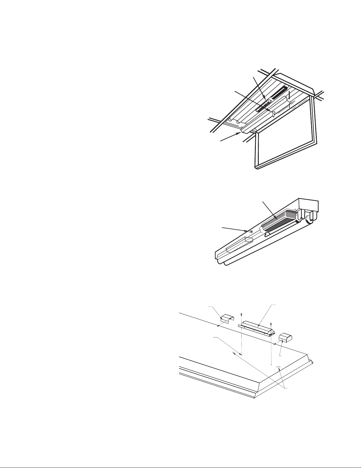
1. Disconnect AC power from the fixture. Remove the
ballast channel cover. Install the emergency ballast
with grounding screws either in the ballast channel
(see illustrations 1 & 2) or on top of the fixture (see
illustration 3 / EBP1400NCX only).
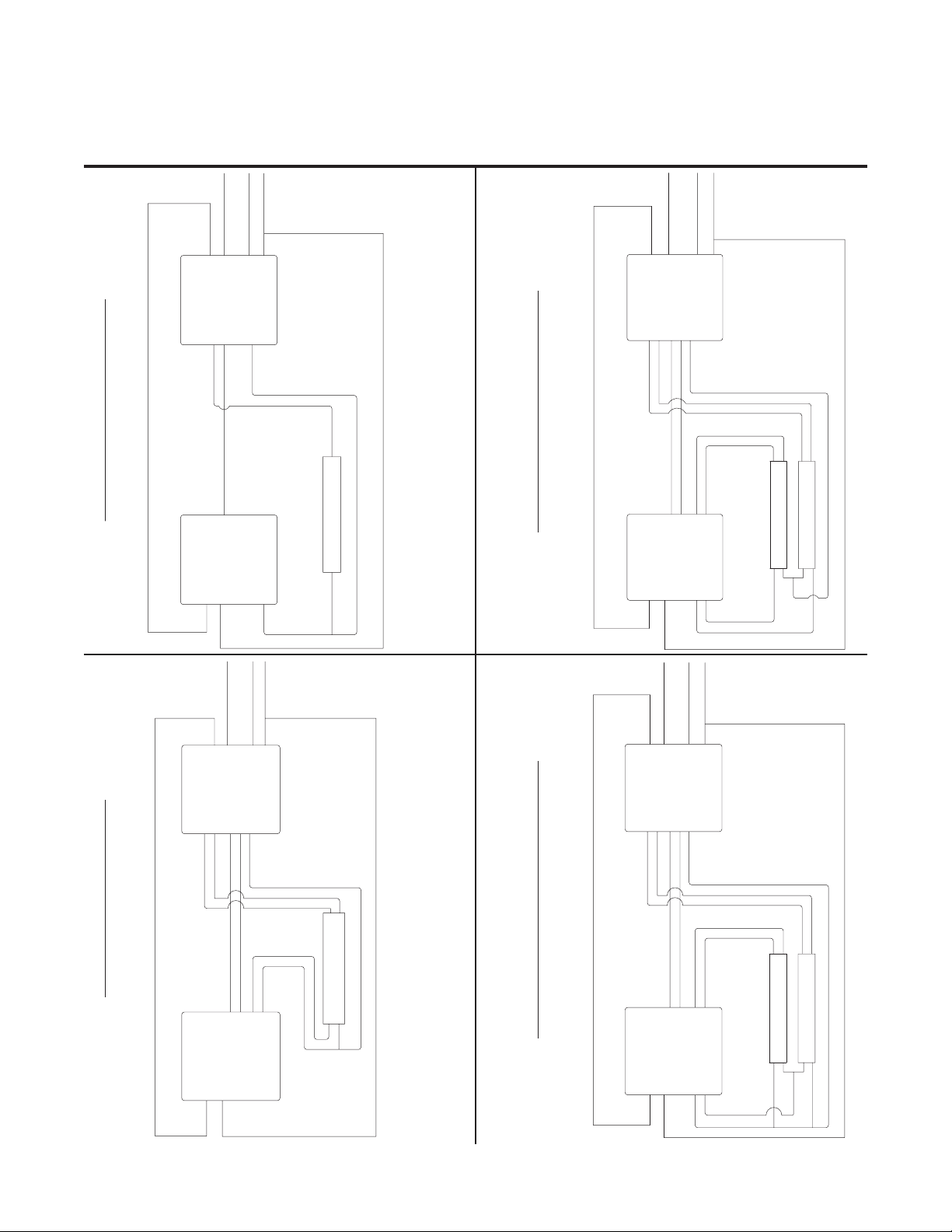
2. Select the appropriate wiring diagram to connect
the emergency ballast to the AC ballast and lamp.
Make sure all connections are in accordance with the
National Electrical Code and any local regulations.
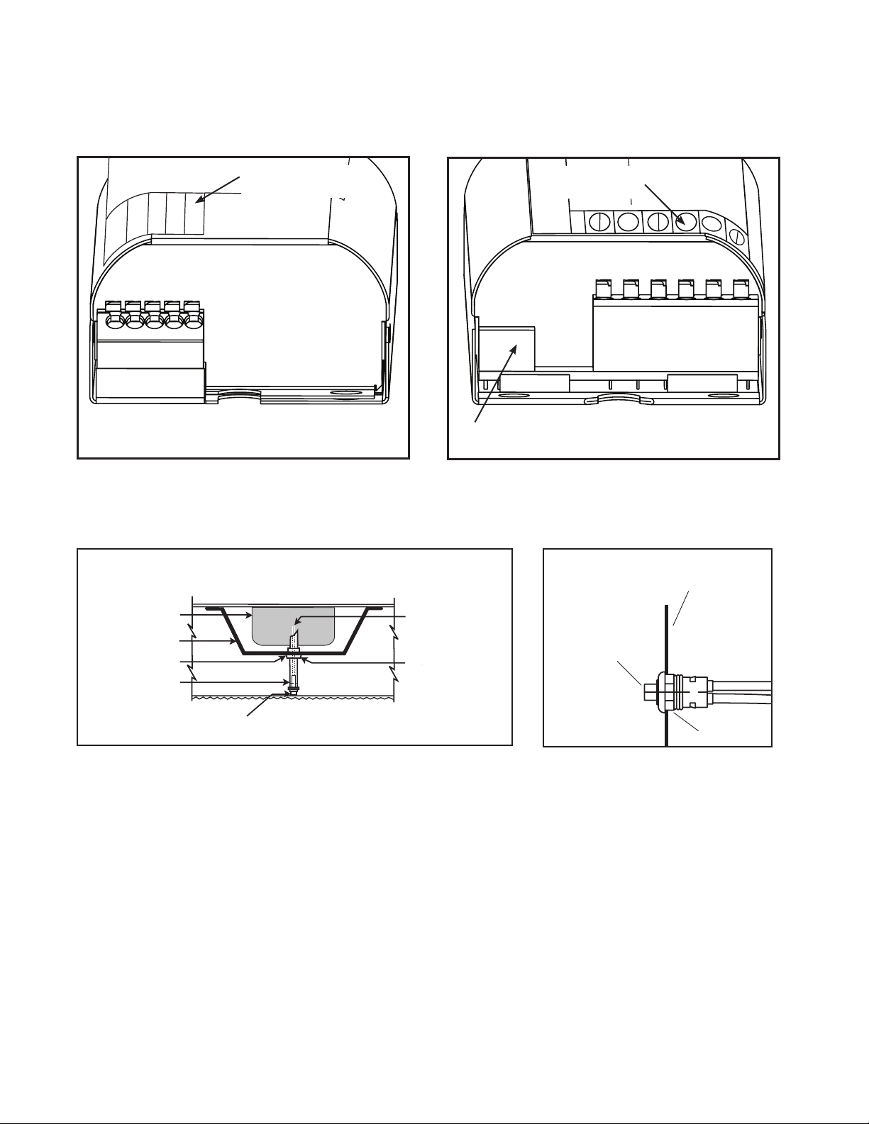
(See Illustrations 4 and 5 for terminals).
3. Refer to the lamp compatibility table for the HIGH
(Red) or Low (Red / White) connection per the lamp(s)
being illuminated by the emergency ballast.
4. Install the test button / indicator light through the
ballast channel cover of a troffer (Illustration 1 & 6)
or through the side of a strip fixture (Illustration 2 &
7). Drill or punch a 7/8” hole to install the test button
/ indicator light as shown in illustration 6. Drill or
punch a 1/2” hole to install the test button / indicator
light as shown in illustration 7. Install the test button
/ indicator light as shown in the selected illustration.
Apply the two included labels (“Charging Indicator
Light” and “Emergency Light Push to Test”) adjacent
to the test button indicator light.
5. In a readily visible location, attach the included label
“CAUTION – This unit Has More Than One Power
Connection Point. To Reduce The Risk Of Electric
Shock, Disconnect Both The Branch Circuit-Breakers
Or Fuses and the Test Button / Indicator Light Before
Servicing”.
6. In an area readily visible during relamping, attach the
included relamping label. Write in the lamp type and
wattage.
7. After installation is complete, connect the test
button / indicator light. The factory installed version
(EBP1400NCF) will have 2 twisted wires (brown and
purple) at the access plate which must be connected
for the fixture to operate in emergency mode.
8 Replace covers being careful not to pinch wires, install
lamps, supply AC power to the emergency ballast.
9. A short term discharge test may be conducted after
the emergency ballast has been charging for one
hour. Charge for 24 hours before conducting a long –
term discharge test. Refer to OPERATION.
Illustration 1
Test Button/
Indicator Light
Ballast
Cover
Illustration 2
Test Button/
Indicator Light
Illustration 3
Wire Bundle
Cover
Drill 1/8˝ Hole
for Mounting
Screws
EBP1400NCX only
Ballast
Emergency
Ballast
Emergency
Ballast
Wire Bundle
Cover
1/2˝ Std. Knockout
7/8˝ Hole w/Bushing
2
EATON ADX142715 Installation instructions
Page 3
EBP1400NCX and EBP1400NCF Instruction Manual
RED / WH
RED
BLUE
BLUE / WH
YELLOW
YELLOW / BK
TEST BU
LIGHT C
Emergenc
Suitable fo
BU
C
fo
Illustration 4
120/240/277
NEUTRAL
LINE
LINE HOT
120/277
LINE
NEUTRAL
Illustration 6
Illustration 5
Terminal labels
AUX COM
AUX N.O.
AUX N.C.
LINE HOT
AUX
COMMON
AUX
N.O.
AUX
N.C.
located here.
Color coded label
LIGHT
TEST
located here.
YELLOW
YELLOW / BK
Emergenc
Suitable
RED / WH
RED
BLUE
BLUE / WH
Test Button / Indicator Light Connector
Illustration 7
Emergency
Ballast
Ballast Channel
Cover
7/8" Punch
Plastic Tubing
(cut to necessary
length)
TROFFER STYLE FIXTURE
Test Button/
Indicator Light
Leads to Test Button/
Indicator Light
7/8" Bushing
Inserted into
Ballast Channel
Cover
STRIP STYLE FIXTURE
Fixture
Test Button/
Indicator Light
Nut
EATON ADX142715 Installation instructions
3
Page 4

EBP1400NCX and EBP1400NCF Instruction Manual
Lamp Compatibility Table
Lamp Type
Number
of Lamps
Lamps Connected to
Low/High (Red) Output
Wattage
T5 1 HIGH (RED) 6 - 25, 39
T5 1 "LOW (RED / WHITE)" 28 - 35
T5HO 1 HIGH (RED) 24
T5HO 1 "LOW (RED / WHITE)" 54 - 80
T5 CIR 1 HIGH (RED) 22 - 55
T8 1 HIGH (RED) 15 - 32
T8 1 "LOW (RED / WHITE)" 59 - 86
T8U 1 HIGH (RED) 32
T9 CIR 1 HIGH (RED) 20 - 32
T12 1 HIGH (RED) 20 - 75
T12 1 "LOW (RED / WHITE)" 75 - 95
T12HO 1 HIGH (RED) 35
T12HO 1 "LOW (RED / WHITE)" 95 - 110
T12VHO 1 "LOW (RED / WHITE)" 215
BIAX 1 HIGH (RED) 18 - 55
OPERATION
When AC power is applied, the charging indicator light is illuminated, indicating the battery is being charged. When
power fails, the emergency ballast automatically switches to emergency power, operating one lamp at reduced
illumination for at least 90 minutes.
MAINTENANCE
Although no routine maintenance is required to keep the emergency ballast functional, it should be checked periodically
to comply with local codes. The following schedule is recommended:
1. Visually inspect the charging light monthly. It should be illuminated.
2. Test the emergency operation of the fixture at 30 day intervals for a minimum of 30 seconds. Depending on
installation, one lamp should operate at reduced illumination.
3. Conduct a 90 – minute discharge test once a year. Depending on installation, one lamp should operate at reduced
illumination for at least 90 minutes.
Refer any service requirements indicated by these checks to qualified personnel.
NOTE: After installing the test button / indicator light, mark it with the appropriate label.
4
EATON ADX142715 Installation instructions
Page 5
EBP1400NCX and EBP1400NCF Instruction Manual
LINE NEUTRAL
LINE HOT
LINE NEUTRAL
LINE NEUTRAL
LINE NEUTRAL
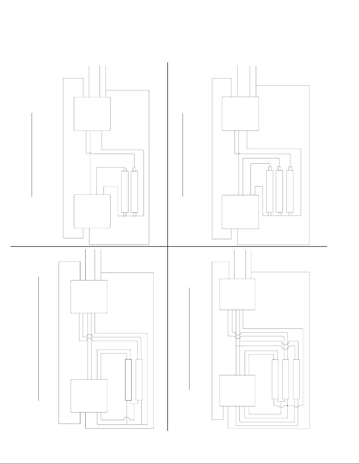
WIRING DIAGRAMS FOR 1-LAMP EMERGENCY OPERATION
TYPICAL SCHEMATICS ONLY. MAY BE USED WITH OTHER BALLAST. CONSULT THE FACTORY FOR OTHER WIRING DIAGRAMS
SWITCHED OR UNSWITCHED LINE HOT
(UNSWITCHED) 120/277
AUX NO
AUX NC
LINE NEUTRAL
LINE HOT
LINE NEUTRAL
SWITCHED OR UNSWITCHED LINE HOT
(UNSWITCHED) 120/277
LINE NEUTRAL
AUX NC
AUX NO
LINE HOT
AUX COM
LINE NEUTRAL
AUX COM
EMERGENCY BALLAST
YELLOW/BK
1 LAMP INSTANT START
YELLOW
BLUE/WH
BLUE
CHOOSE BASED
BLUE
RED OR RED/WH
ON LAMP
AC BALLAST
LINE HOT
RED
LINE NEUTRAL
SWITCHED OR UNSWITCHED LINE HOT
(UNSWITCHED) 120/277
AUX NC
AUX NO
LINE HOT
AUX COM
LINE NEUTRAL
LAMP ("EMERGENCY")
EMERGENCY BALLAST
YELLOW/BK
SERIES YELLOW FILAMENT
2 LAMP RAPID START SERIES LAMP
LINE HOT
AUX COM
CHOOSE BASED
ON LAMP
YELLOW
BLUE/WH
BLUE
RED OR RED/WH
BLUE
BLUE
RED
RED
AC BALLAST
YELLOW
YELLOW
SWITCHED OR UNSWITCHED LINE HOT
(UNSWITCHED) 120/277
LINE NEUTRAL
AUX NC
AUX NO
LINE HOT
LINE NEUTRAL
LAMP-1
("EMERGENCY")
LAMP-2
EMERGENCY BALLAST
YELLOW/BK
1 LAMP RAPID START
YELLOW
BLUE/WH
BLUE
CHOOSE BASED
ON LAMP
BLUE
RED OR RED/WH
BLUE
RED
RED
AC BALLAST
LAMP ("EMERGENCY")
EMERGENCY BALLAST
YELLOW/BK
YELLOW
BLUE/WH
BLUE
CHOOSE BASED
ON LAMP
BLUE
RED OR RED/WH
BLUE
RED
RED
LAMP-1
("EMERGENCY")
LAMP-2
PARALLEL YELLOW FILAMENT
AC BALLAST
YELLOW
YELLOW
2 LAMP RAPID START SERIES / PARALLEL LAMP
EATON ADX142715 Installation instructions
LINE HOT
5
Page 6
EBP1400NCX and EBP1400NCF Instruction Manual
LINE NEUTRAL
LINE NEUTRAL
LINE NEUTRAL
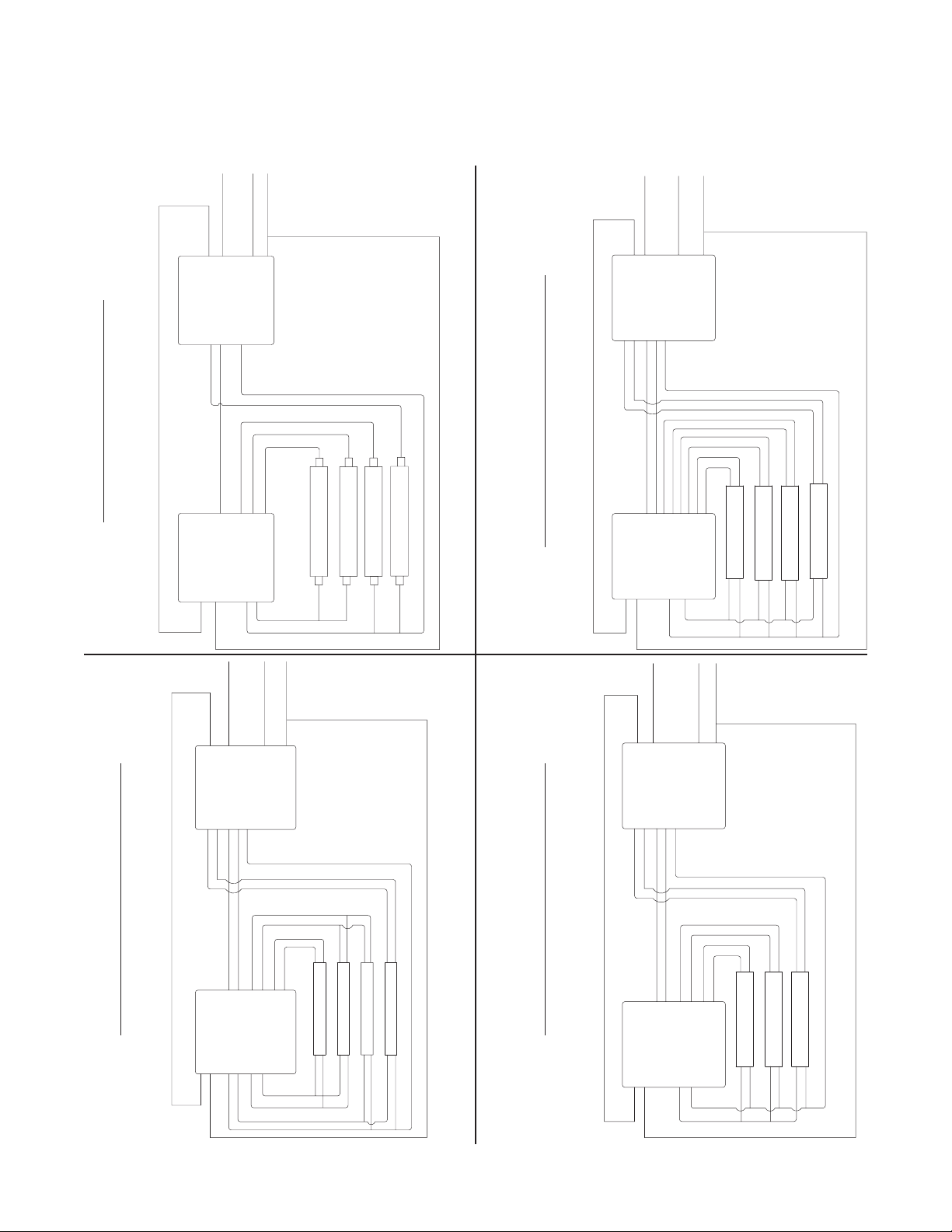
WIRING DIAGRAMS FOR 1-LAMP EMERGENCY OPERATION
TYPICAL SCHEMATICS ONLY. MAY BE USED WITH OTHER BALLAST. CONSULT THE FACTORY FOR OTHER WIRING DIAGRAMS
SWITCHED OR UNSWITCHED LINE HOT
(UNSWITCHED) 120/277
LINE NEUTRAL
AUX NC
AUX NO
LINE HOT
AUX COM
EMERGENCY BALLAST
YELLOW/BK
YELLOW
BLUE/WH
BLUE
BLUE
RED OR RED/WH
RED
BLUE
LINE NEUTRAL
CHOOSE BASED
ON LAMP
2 LAMP INSTANT START
AC BALLAST
LINE HOT
LAMP-2 ("EMERGENCY")
LAMP-1
SWITCHED OR UNSWITCHED LINE HOT
AUX COM
EMERGENCY BALLAST
YELLOW/BK
YELLOW
3 LAMP INSTANT START
(UNSWITCHED) 120/277
AUX NC
AUX NO
LINE HOT
CHOOSE BASED
BLUE/WH
BLUE
RED OR RED/WH
BLUE
BLUE
BLUE
LINE NEUTRAL
LINE NEUTRAL
ON LAMP
RED OR YELLOW
AC BALLAST
LINE HOT
LAMP-1
LAMP-2
LAMP-3 ("EMERGENCY")
SWITCHED OR UNSWITCHED LINE HOT
(UNSWITCHED) 120/277
LINE NEUTRAL
AUX NC
AUX NO
LINE HOT
AUX COM
EMERGENCY BALLAST
YELLOW/BK
LAMP PARALLEL YELLOW FILAMENT
2 LAMP RAPID START OSRAM SYLVANIA SERIES
6
EATON ADX142715 Installation instructions
LINE HOT
YELLOW
BLUE/WH
BLUE
BLUE
BLUE
AC BALLAST
LINE NEUTRAL
CHOOSE BASED
ON LAMP
RED OR RED/WH
RED
RED
YELLOW
YELLOW
LAMP-1
("EMERGENCY")
LAMP-2
3 LAMP RAPID START SERIES LAMP
SWITCHED OR UNSWITCHED LINE HOT
(UNSWITCHED) 120/277
LINE NEUTRAL
AUX NC
AUX NO
LINE HOT
AUX COM
EMERGENCY BALLAST
YELLOW/BK
YELLOW
BLUE/WH
BLUE
BLUE/WHT
BLUE/WHT
LINE NEUTRAL
CHOOSE BASED
ON LAMP
RED OR RED/WH
RED
RED
LAMP-1
PARALLEL YELLOW FILAMENT
AC BALLAST
BLUE
BLUE
YELLOW
LINE HOT
YELLOW
LINE NEUTRAL
("EMERGENCY")
LAMP-2
LAMP-3
Page 7
EBP1400NCX and EBP1400NCF Instruction Manual
LINE NEUTRAL
LINE NEUTRAL
LINE NEUTRAL
WIRING DIAGRAMS FOR 1-LAMP EMERGENCY OPERATION
TYPICAL SCHEMATICS ONLY. MAY BE USED WITH OTHER BALLAST. CONSULT THE FACTORY FOR OTHER WIRING DIAGRAMS
SWITCHED OR UNSWITCHED LINE HOT
(UNSWITCHED) 120/277
AUX NC
LINE HOT
LINE NEUTRAL
LINE NEUTRAL
SWITCHED OR UNSWITCHED LINE HOT
(UNSWITCHED) 120/277
LINE NEUTRAL
AUX NC
AUX NO
LINE HOT
AUX COM
LINE NEUTRAL
AUX NO
AUX COM
EMERGENCY BALLAST
YELLOW/BK
YELLOW
BLUE/WH
BLUE
CHOOSE BASED
ON LAMP
BLUE
RED OR RED/WH
BLUE
RED
RED
4 LAMP INSTANT START
AC BALLAST
LINE HOT
YELLOW
YELLOW
SWITCHED OR UNSWITCHED LINE HOT
(UNSWITCHED) 120/277
LINE NEUTRAL
AUX NC
AUX NO
AUX COM
LINE HOT
LINE NEUTRAL
LAMP-1
LAMP-2
LAMP-3
LAMP-4 ("EMERGENCY")
YELLOW
BLUE/WH
BLUE/WHT
ON LAMP
BLUE
RED OR RED/WH
RED/WHT
RED/WHT
BLUE
BLUE/WHT
BLUE
RED
RED
LAMP-1
LAMP-2
("EMERGENCY")LAMP-4
LAMP-3
YELLOW/BK
PARALLEL YELLOW FILAMENT
BALLAST
EMERGENCY
CHOOSE BASED
AC BALLAST
4 LAMP RAPID START PARALLEL LAMP
YELLOW
YELLOW
LINE HOT
SWITCHED OR UNSWITCHED LINE HOT
(UNSWITCHED) 120/277
LINE NEUTRAL
AUX NC
AUX NO
AUX COM
LINE HOT
LINE NEUTRAL
YELLOW
BLUE/WH
BLUE
ON LAMP
BLUE
RED OR RED/WH
BLUE/WHT
BLUE/WHT
BLUE
RED
RED
LAMP-1
LAMP-2
("EMERGENCY")LAMP-4
LAMP-3
YELLOW/BK
BALLAST
EMERGENCY
CHOOSE BASED
PARALLEL YELLOW FILAMENT
4 LAMP RAPID START SERIES LAMP
AC BALLAST
BROWN
BROWN
YELLOW
LINE HOT
YELLOW
LINE NEUTRAL
YELLOW
BLUE/WH
RED/WHT
ON LAMP
BLUE
RED OR RED/WH
BLUE
BLUE
RED/WHT
RED
RED
LAMP-1
("EMERGENCY")LAMP-3
LAMP-2
YELLOW/BK
PARALLEL YELLOW FILAMENT
BALLAST
EMERGENCY
CHOOSE BASED
AC BALLAST
3 LAMP RAPID START PARALLEL LAMP
YELLOW
YELLOW
LINE HOT
EATON ADX142715 Installation instructions
7
Page 8
YELLOW/BK
YELLOW
BLUE/WH
BLUE
RED OR RED/WH
CHOOSE BASED
ON LAMP
AUX COM
AUX NO
AUX NC
LINE HOT
LINE NEUTRAL
(UNSWITCHED) 120/277
LINE NEUTRAL
WIRE LAMPS USING DIAGRAM PER
# OF LAMPS AND BALLAST TYPE
SWITCHED LINE HOT
SWITCHED LINE HOT
LINE NEUTRAL
BI-LEVEL
AC BALLAST
EMERGENCY BALLAST
EBP1400NCX and EBP1400NCF Instruction Manual
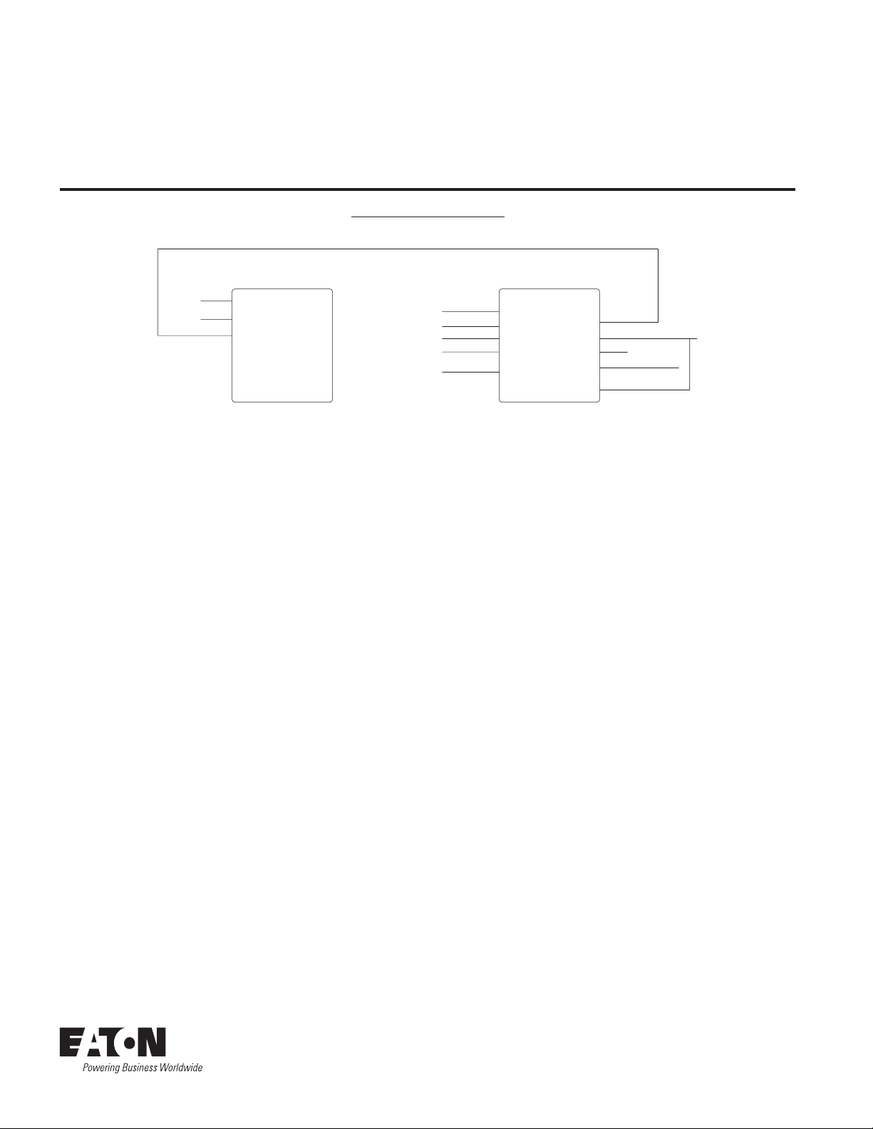
WIRING DIAGRAMS FOR 1-LAMP EMERGENCY OPERATION
TYPICAL SCHEMATICS ONLY. MAY BE USED WITH OTHER BALLAST. CONSULT THE FACTORY FOR OTHER WIRING DIAGRAMS
BI LEVEL BALLAST
When using the auxillary relay to switch the neutral line, the Emergency and A.C. ballasts
must be on the same branch circuit.
Warranties and Limitation of Liability
Please refer to www.cooperlighting.com/WarrantyTerms for our terms and conditions.
Eaton
1121 Highway 74 South
Peachtree City, GA 30269
P: 770-486-4800
www.eaton.com/lighting
Canada Sales
5925 McLaughlin Road
Mississauga, Ontario L5R 1B8
P: 905-501-3000
F: 905-501-3172
© 2015 Eaton
All Rights Reserved
Printed in USA
Publication No. ADX142715
June 19, 2015 9:44 AM
Eaton is a registered trademark.
All trademarks are property
of their respective owners.
Product availability, specifications,
and compliances are subject to
change without notice
 Loading...