

Sure Heat Manufacturing RP-24-N, RP-24-P, RP-30-N, RP-18-P, RP-30-P Installation And Operating Instructions For
...
SURE HEAT MANUFACTURING
Installation and Operating Instructions for
NATURAL & L.P. GAS
A.G.A. SINGLE & DUAL BURNER
VENTED UNITS
MMooddeell:
RRPP
GGOO
GGLLO
O
WWO
O
CCO
O
SSO
O
TTO
O
SSMMP
P
:
(18,24,30)-N
18,24,30)-N
(
(18,24,30)-N
(18,24,30)-N
(18,24,30)-N
(18,24,30)-N
(18,24,30)-N
(18,24,30)-N
FFoorr uussee wwiitthh NNaattuurraall GGaass OOnnllyy
MMooddeell:
CCL
L
PPOOS
S
PPO
O
CCC
C
GGB
B
SSQ
Q
CCF
F
:
(18,24,30)-N
(18,24,30)-N
(18,24,30)-N
(18,24,30)-N
(18,24,30)-N
(18,24,30)-N
(18,24,30)-N
MMooddeell:
RRPP
GGOO
GGLLO
O
WWO
O
CCO
O
SSO
O
TTO
O
SSMMP
P
:
(18,24,30)-P
(18,24,30)-P
(18,24,30)-P
(18,24,30)-P
(18,24,30)-P
(18,24,30)-P
(18,24,30)-P
(18,24,30)-P
FFoorr uussee wwiitthh PPrrooppaannee GGaass OOnnllyy
MMooddeell:
CCL
L
PPOOS
S
PPO
O
CCC
C
GGB
B
SSQ
Q
CCF
F
Sure Heat Manufacturing
3130 Moon Station Road
Kennesaw, GA 30144
Tel: (770) 422-8008
Fax: (770) 424-3842
WARNING: It is very important to read the instructions in this manual before starting installation.
- Do not attempt to modify or alter the construction of the fireplace or its components. Any modification
or alteration of construction may void the warranty of these units.
WARNING: Solid fuel shall not be burned in a fireplace where a decorative gas appliance is installed.
:
18,24,30)-P
(
(18,24,30)-P
(18,24,30)-P
(18,24,30)-P
(18,24,30)-P
(18,24,30)-P
(18,24,30)-P
WARNING: Improper installation, adjustment, service or maintenance can cause
injury or property damage. Refer to this manual. For assistance or additional
information, consult a certified installer, service agency or the gas supplier.
- Do not store or use gasoline or other flammable vapors or liquids in the vicinity of this or any
other appliance
- WHAT TO DO IF YOU SMELL GAS:
• Do not try to light any appliance.
• Do not touch any electrical switch.
• Do not use any telephone in your building.
• Immediately call your gas supplier from a neighbor’s telephone.
• Follow the gas suppliers instructions.
• If you cannot reach your gas supplier, call the fire department.
FOR YOUR SAFETY

- Due to high temperatures, the appliance should be located out of traffic and away from furniture and
draperies.
- Do not place clothing or other flammable material on or near the appliance.
Children and adults should be alerted to the hazards of high surface temperature and should stay away to
avoid burns or clothing ignition.
- Young children should be carefully supervised when they are in the same room with the appliance.
- Please retain this manual for future reference.
The installation must conform with local codes, or in the absence of local codes, with the National Fuel Gas
Code ANSI Z223.1, latest edition.
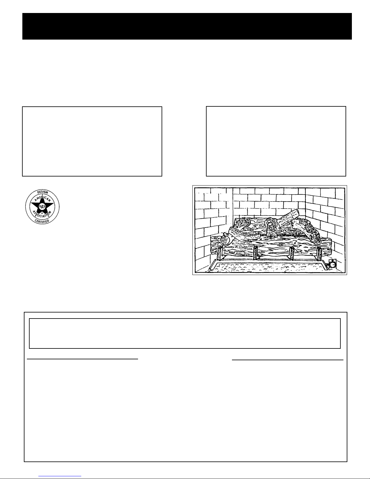
This appliance must be installed only in a solid fuel fireplace with a working flue and constructed of noncombustible material.
Installation and repair should be done by a qualified service person.
The appliance should be inspected before use and at least annually by a qualified service person. More frequent cleaning may be necessary due to excessive dust or carpet lint. It is important that the circulating air
passageways be kept clean.
Keep appliance clear and free from combustible materials, gasoline and other flammable vapors and liquids.
IMPORTANT INFORMATION
Fireplace Sizing Guide:
Set Size
18”
24”
30”
Opening
Height
16 1/2”
18”
20”
Front
W
idth
28”
32”
36”
Rear
Width
21”
24”
28”
Fireplace
Depth
15”
15”
15”
Chimney
Opening
50 sq. in.
50 sq. in.
50 sq. in.
The minimum opening that must be provided by the fireplace chimney to vent the unit properly is shown above
in the sizing chart.
It is necessary to provide adequate combustion and ventilation air. Air for combustion and ventilation must not
be obstructed. Provide adequate clearance around air opening in the combustion chamber and adequate
accessibility clearance for servicing and proper operation.
NEVER obstruct the front opening of the fireplace.
WARNING:
Any safety guard removed for servicing an appliance must be replaced before operating the appliance
Unpack the appliance carefully and inspect for missing parts or damages that may have occurred during
shipping. If any part of the appliance is missing or damaged, please notify Sure Heat Manufacturing at
(770) 422-8008.
The fireplace needs to be properly prepared before installing this fireplace unit.
f gas supply to the fireplace.
urn of
1. T
2. Clean chimney and fireplace floor of any combustible material to limit the smell from the system.
Gas Piping and Gas Pressure Requirements
PREPARATION
Check the type of gas that is supplied to your fireplace. Only install the unit that is equipped to operate on the gas
that is supplied to your fireplace.
All gas piping must be installed to comply with local and national fuel gas codes.
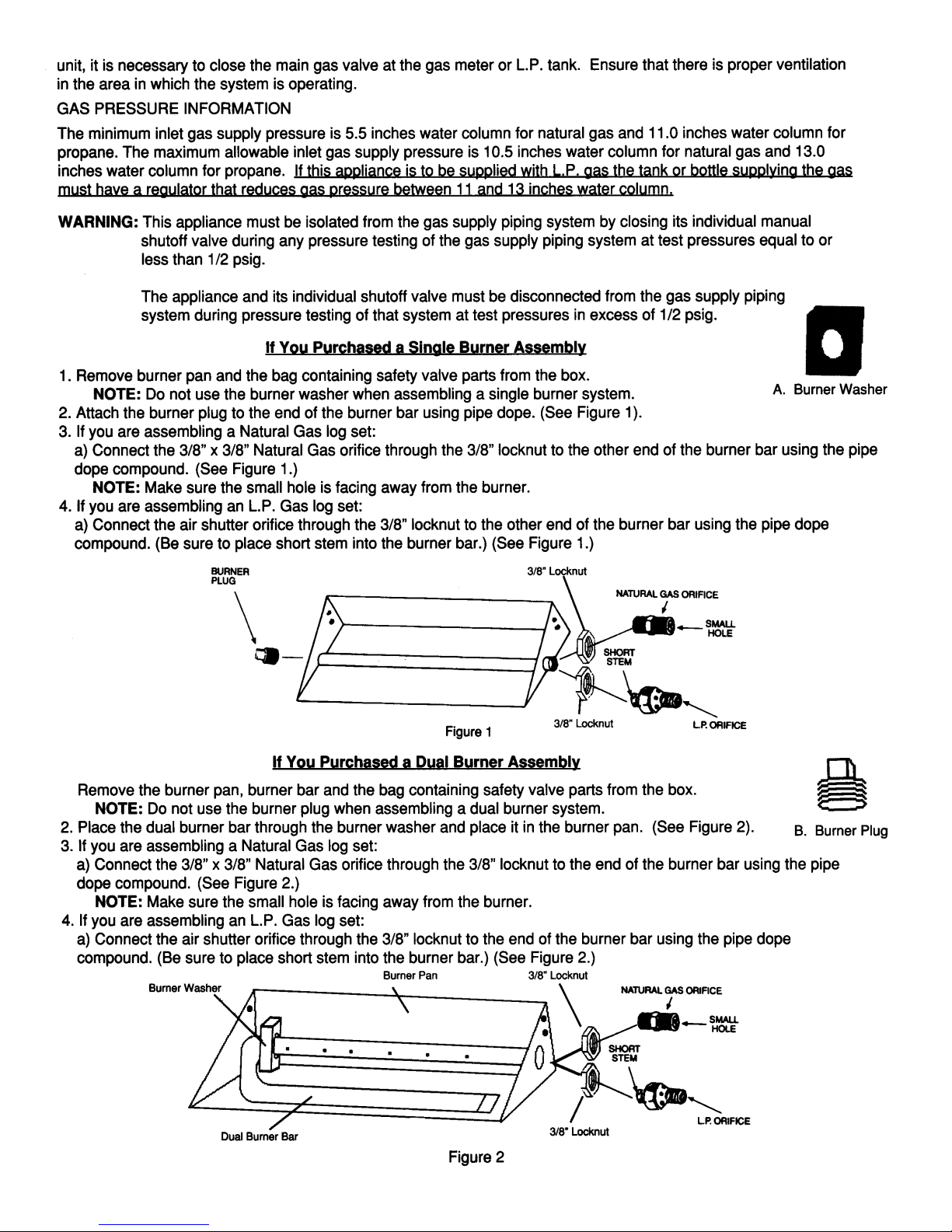
Compounds used on threaded joints of gas piping must be resistant to the action of L.P. gas. Before installing the
INSTALLATION
Unpacking
Fireplace Preparation
Page 2
Page 3
Page 4
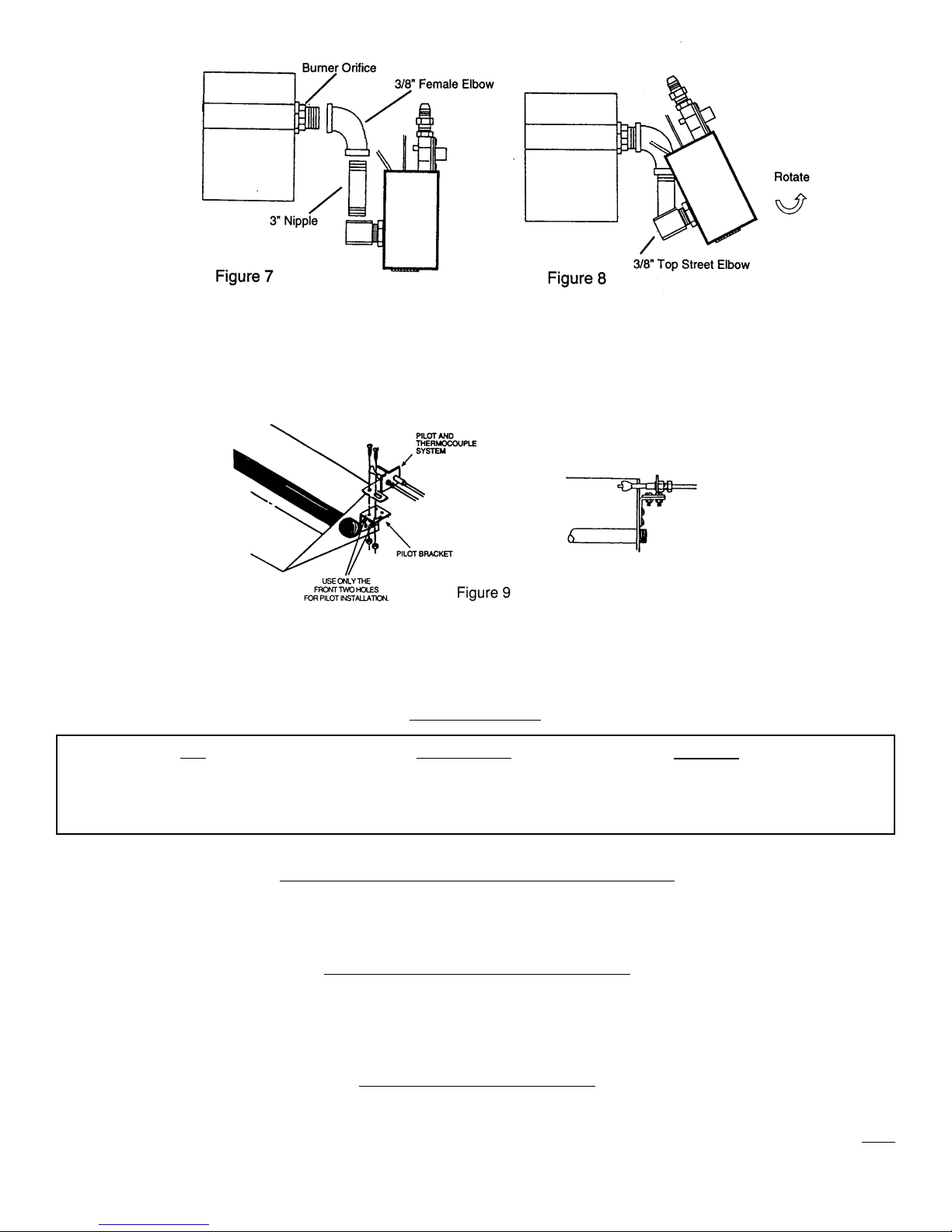
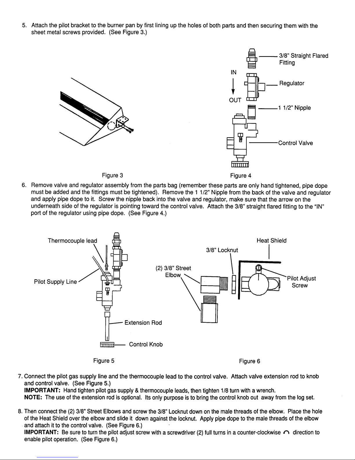
9. Using pipe dope connect the 3” Nipple to the Street Elbow attached to the valve assembly and to the 3/8” Female
Elbow. Then connect the 3/8” Female Elbow, which is connected to the entire valve assembly, to the Burner Orifice
using pipe dope. (See Figure 7.)
10. The valve assembly could be rotated to better conceal the controls. Simply rotate the entire valve assembly by
turning the top 3/8” Street Elbow with a wrench (See Figure 8.)
11. Connect pilot and thermocouple to pilot bracket using the screws and nuts provided. Be sure that the pilot and the
thermocouple is just hanging over the burner pan. (See Figure 9.)
NOTE: Carefully bend the pilot tubing when attaching the pilot burner to the burner pan. Care should be
taken not to kink the tubing which would restrict the gas flow to the pilot burner.
BTU Information
Set
18”
24”
30”
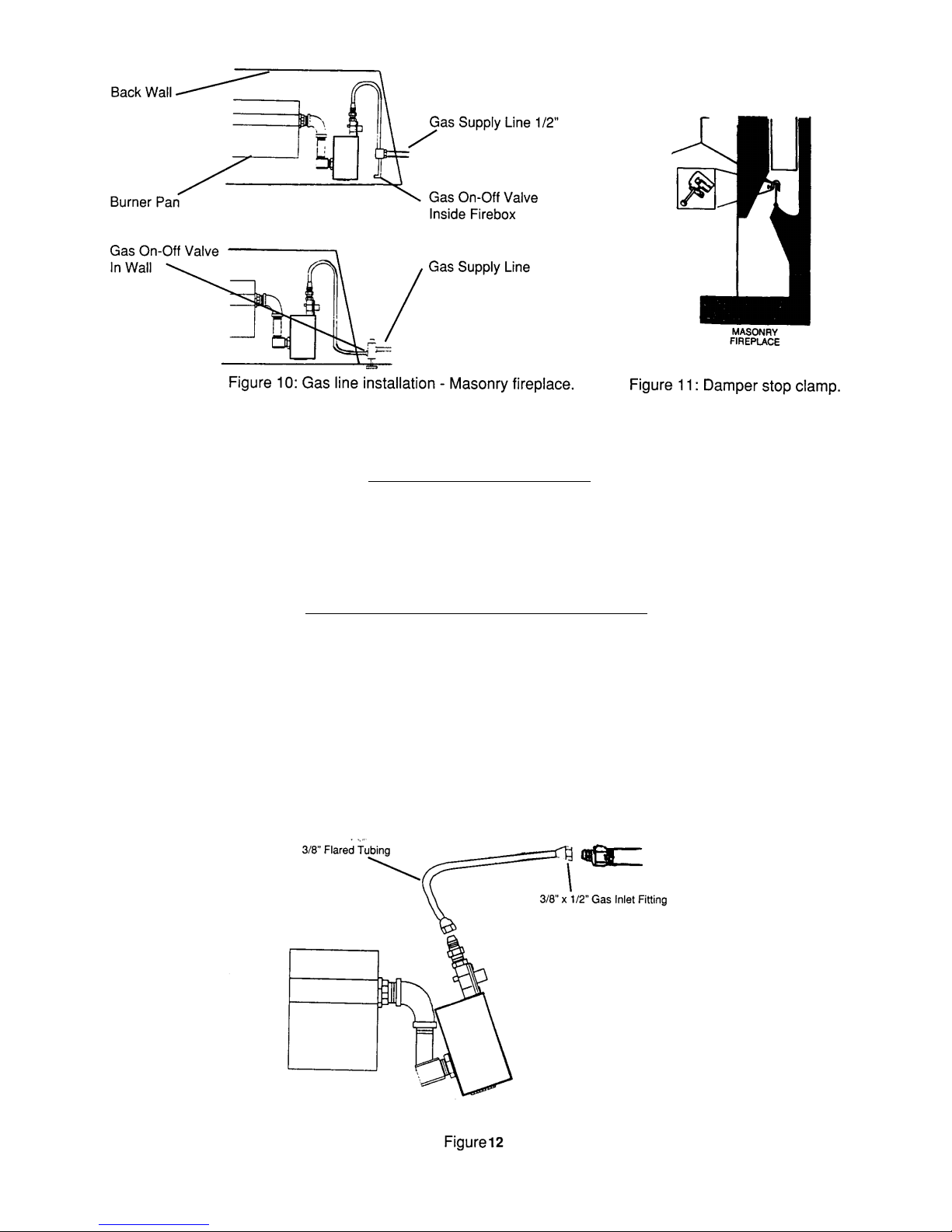
Installation to Existing Gas Line in Fireplace
A manual on/off valve should be present within easy reach of the gas log set. If a manual valve is not present, one must
be installed prior to the gas log installation.
1/2” gas supply line must be provided to the fireplace. Most installations require drilling and access hole through the
A
masonry wall. The supply line should be secured and sealed by mortar within the access hole. The supply line should
also have an on/off valve in the wall or inside the fireplace. (See Figure 10.)
This appliance is only to be installed and burned in a fully vented fireplace with a fully functional damper and chimney
damper clamp is provided to allow any pilot combustion products to vent.
that is free of any obstructions.
be operated with the damper in the fully opened position. (See Figure 11.)
A
Natural Gas
48,000
70,000
70,000
Installation in a Masonry Fireplace
Damper Clamp Installation
Page 5
L.P. Gas
48,000
70,000
70,000
The unit
must
Burner System Location
1. The Burner system should be located towards the back and centered in the combustion chamber of the
vented fireplace. The burner system should be centered from left to right, with about an inch of space on
either side.
Connecting Gas Supply to Burner Pan
1. Place burner system in proper location.
2. Attach brass 3/8” to 1/2” gas inlet fitting to the 1/2” gas supply stub.
3. Carefully bend the flared tubing as needed to make the connection between the burner assembly and the
gas inlet fitting. Next attach the flared tubing to the burner assembly first, then to the gas inlet fitting.
Avoid kinking the flared tubing while bending. If tubing must be cut, use a tube cutter. Flare the cut end of
the tube with a flaring tube.
Page 6
 Loading...