

Page 1
S
U
R
S
U
Installation and Operating Instructions for
EENNEERRGGYY EEFFFFIICCIIEENNTT
R
E
E
H
H
E
E
A
A
T
T
NNAATTUURRAALL GGAASS FFIIRREEPPLLAACCEE LLOOGGS
HH BBUURRNNEER
MMooddeellss:: BBRROO1188NNGG,, BBRROO2244NNGG,, CCCC2211NNGG
DANGER:
FAILURE TO FOLLOW THESE INSTRUCTIONS CAREFULLY AND WITHOUT ERROR, OR FAILURE TO HEED ANY AND ALL
WARNINGS IN THESE INSTRUCTIONS CAN RESULT IN AN EXPLOSION, FIRE OR THE PRODUCTION OF CARBON MONOXIDE GAS WHICH CAN CAUSE PROPERTY DAMAGE, BODILY INJURY OR DEATH.
R
S
NOTE: THIS UNIT CANNOT
BE CONVERTED TO
DIFFERENT GAS TYPES.
PLEASE READ these instructions carefully before you begin to install this gas log set.
WARNING: If the information in this manual is not followed exactly, a fire or explosion may result
causing property damage, personal injury or loss of life.
- Do not store or use gasoline or other flammable vapors or liquids in the vicinity of this or any
other appliance.
- WHAT TO DO IF YOU SMELL GAS:
• Do not try to light any appliance
• Do not touch any electrical switch.
• Do not touch any telephone in your building.
• Immediately call your gas supplier from a neighbor's telephone.
• Follow the gas suppliers instructions.
• If you cannot reach your gas supplier, call the fire department.
SSuurree HHeeaatt MMaannuuffaaccttuurriinng
1860 West Oak Parkway
Marietta, GA 30062
Tel: (770) 422-8008
Fax: (770) 424-3842
g
- Installation and service must be performed by a qualified installer, service agency or the
gas supplier.
©SURE HEAT MFG. 2007
Complies with L.A. RGA 2-72
Page 2
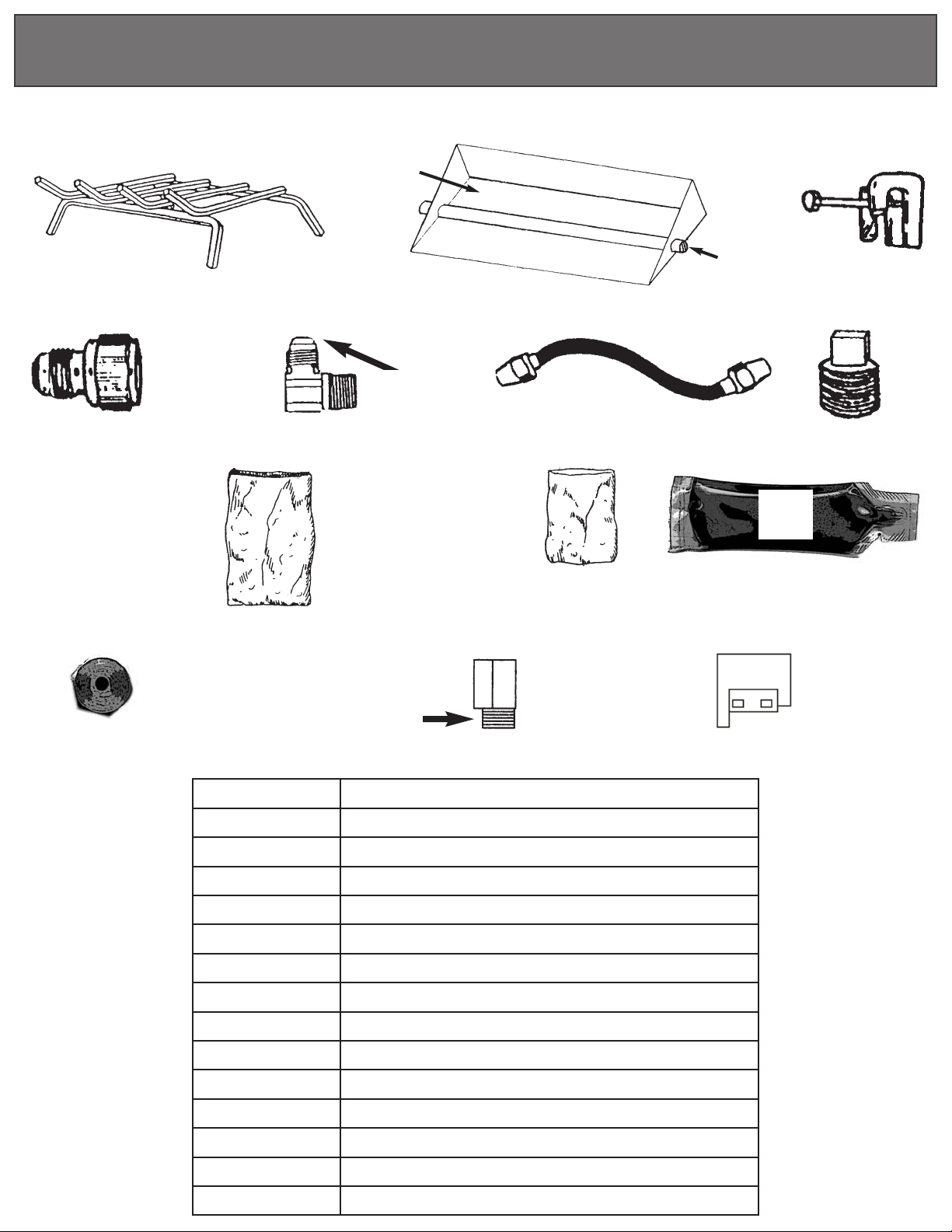
PARTS LIST
Figure 1
2A
4
8
GRANULES
(HEAVYWEIGHT
BAG)
11
TO 1/2"
GAS LINE
1
5
FLARED
END
9
(LIGHTWEIGHT
TO
BURNER
BAR
GLOWING
EMBERS
BAG)
12
2B
6
3
7
10
13 x (2)
PART NO. DESCRIPTION
1 Log Grate
2A Burner Pan
2B Burner Bar
3 Damper Stop Clamp
4 3/8" Flared to 1/2" Gas Inlet Fitting
5 3/8" Brass Orifice Elbow-Flared
6 3/8" Flared Tubing
7 Burner Bar Plug
8 Granules
9 Glowing Embers
10 Pipe Dope
11 Orifice
12
13 Back Log Stand Off
3/8" Brass Street Elbow
Page 3
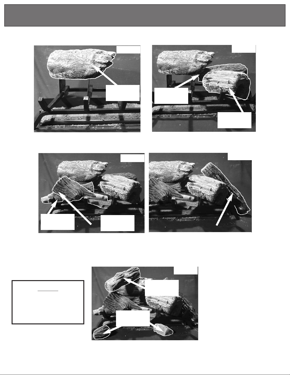
LOG PLACEMENT
MODELS:
MODELS:
Place back log onto the 2 standoffs
BRO18NG &
BRO18NG &
Step 1
Left
Back Log
Step 3
BRO24NG
BRO24NG
Right
Back Log
Place right back log and
right front log onto grate
Step 2
Right
Front Log
Step 4
Middle
Log
Place the middle log in front of the
left back log. Then place the left
front log in front of the middle
log onto the grate
NOTE:
MODEL BRO18NG
will only have 7 logs. It will
not contain the middle log
or one of the small logs.
Right
Front Log
Place the side log in between
the right back log and
right front log
Step 5
Top
Log
Small
Logs
Place the two smaill logs in front
of the grate as shown and the
top log on top of the left back log
Page 4

LOG PLACEMENT
MODEL:
MODEL:
Step 1
Place back log onto the 2 standoffs
Step 2
CC21NG
CC21NG
Standoffs
Back
Log
Front
Log
Place front log in front of back log
Step 3
Top
Logs
Place top logs on top of back and front logs
Step 4
Top
Logs
Place remaining top logs as shown above
Page 5

PREFABRICATED
FIREPLACE
MASONRY
FIREPLACE
IMPORTANT INFORMATION
1. This gas log set is only to be installed and burned in a fully vented fireplace with a fully functional damper
and chimney that is free of any obstructions. The fireplace must be constructed of non-combustible
materials and approved to burn wood.
fitted with a gas log set.
2.
To operate this gas log set, the fireplace damper must be fully opened and locked.
3. The smallest or minimum dimension of the chimney flue must be 8 inces in diameter.
• Do not use an Energy Efficient Gas Log Set if it is smaller than 8 inches.
• Do not use an Energy Efficient Gas Log Set if fumes from the burner emerge into the room when the
damper is fully open. This indicates that ther is not adequate draft for our log sets and the gas log set
must not be used until fireplace draft is corrected.
4. This appliance must be installed with a Damper Stop Clamp (Part # 9). When operating this gas log set,
the flue damper must be fully open.
WARNING: Improper use or installation may cause Carbon Monoxide Poisoning. Carbon Monoxide,
which is an odorless and colorless gas, is a by-product of combustion. Caution must be taken to insure
the fireplace is properly vented when logs are in use. To avoid having potentially dangerous fumes enter
the living area, be sure the chimney is drawing properly and has sufficient draft.
Warning: Do not burn wood or other material in any fireplace
5. A fireplace screen must be in place when operating this gas log sete. This screen shall have an opening(s)
for the introduction of combustion air. If the fireplace has glass doors, operate this gas set with the doors
fully opened.
6. The nominal inlet gas pressure for this appliance is 7" water column for natural gas.
7. This gas log appliance and its individual shutoff valve must be disconnected from the gas supply piping
system during any pressure testing at pressures in excess of 1/2 PSIG.
• This appliance must also be disconnected from the gas supply system by closing its individual manual
shutoff valve during an pressure testing at pressures equal to or less than 1/2 PSIG.
FIREPLACE PREPARATION
A. Remove all ash and debris from floor of fireplace.
B. Open fireplace damper fully and install Damper Stop Clamp with
1/4 x 2"
accidental closure of the damper while in use. (See Figure 2)
• Should Damper Stop Clamp supplied not fit, a permanent Damper
set screw (Part # 9). This clamp is designed to prevent
Stop Clamp must be installed that will keep the damper open at a
distance of not less that 1 1/2".
C. Prior to connecting the gas log set, make sure that the gas supply to
the fireplace is completely shut off.
Installtaion of this Energy Ef
ficient Gas Log Set and provisions for combustion and ventilation air
must conform with the National Fuel Gas Code ANSI Z223.1 and applicable local codes.
Figure 2. Damper Stop Clamp
Page 6

FIREPLACE PREPARATION (CONT.)
D. Installation to existing gas line in fireplace. A manual ON-OFF valve should be present within easy
reach of the gas log set. If a manual valve is not present, one must be installed prior to the gas log
installation.
E.
Pre-fabricated fireplace. Refert to the manufacturer's fireplace instruction manual for specific information
regarding the running of a gas line into that particular model
• A typical pre-fab installation involves the insertion of a 1/2 inch gas pipe through the gas line tube
provided by each manufacturer
rermoved as the gas pipe is punched through the fireplace
• An ON-OFF valve should be placed within easy reach of the fireplace either inside the fireplace or in
the wall. Re-pack any insulation removed from the gas line tube. (See Figure 3)
F.
Masonry fireplaces. A 1/2 inch gas supply line must be provided to the firebox. Most installations require
drilling an access hole through the masonry wall. The supply line should be secured and sealed by mortar
within the access hole. The supply line should also have an ON-OFF valve either in the wall or inside the
fireplace. (See Figure 4)
outside the fireplace. The knockout on the inside of the fireplace is
Figure 3. Gas line installation - Pre-fabricated Fireplace Figure 4. Gas line installation - Masonry fireplace
GAS LOG INSTALLATION
(See Figure 1 Parts List as a guide to reference part numbers)
BURNER P
AN ASSEMBL
Y
(NOTE: Use pipe compound on all male threads to seal joints)
A. Determine if fireplace has a right or left-hand gas line feed. Uses burner bar plug (Part # 13) to seal off
the end of the burner bar (Part #8B) that will not be attached to the gas supply line.
B. Install the orifice (Part #17) in to the 3/8" Brass orifice elbow (Part #11).
C. Attach the 3/8" brass street elbow (Part #19) to the side of the burner pan that the gas line will be attached
to. (See Fig. 5 on following page)
D. Attach the 3/8" brass orifice elbow (Part #11) to the 3/8" brass street elbow (22 Fig. 6-7 on following page)
NOTE: THIS FITTING IS INTERNALLY MACHINED FOR USE AS THE ORIFICE ON NATURAL GAS
INSTALLATIONS. DO
NOT USE FOR L.P
. OR PROP
ANE GAS
APPLAICA
TIONS
Page 7

Fig. 5
Fig. 6
Fig. 7
CONNECTING GAS SUPPLY TO BURNER PAN
(If a Safety Pilot Kit is to be used, please refer to separate installation instructions). These instructions refer to the
Natural Gas applications installed without a Safety Pilot Kit. (Pilot Safety Kit available at your local dealer).
A. Place Burner Pan assembly in the center of the fireplace.
B. Attach Brass 3/8" Flared to 1/2" Gas Inlet Fitting (Part # 10) to the 1/2 inch gas supply stub.
C. Attach 3/8" Flared Tubing (Part # 12) to the 3/8" Brass orifice Elbow (Part # 11). Attach opposite end to gas supply
line by carefully bending the flared tubing as needed to make the connection. Avoid kinking the flared tubing while
bending. If tubing must be cut, use a tube cutter and flare the cut end of the tube with a flaring tool.
D. Be certain all connections are tight and use pipe compound on all male threads to seal joints.
with a soapy water solution with the gas supply turned on. If bubble appear on any connection, re-tighten and re-test.
Once it is determined there are no leaks whatsoever
, turn off gas supply and move to next assembly step.
Test all connections
GRANULE, EMBER AND LOG GRATE PLACEMENT
A. Spread granules (Part #14) over the installed burner pan. Granules should
not fill up the entire pan. The granules should stop 3/4" - 1" from the top of
the pan. Slope the Granules down toward the front of the pan without over
flowing them over the front lip of the burner pan. (See Fig. 8)
B. Spread glowing embers (Part # 15) over the top of the granules, covering
the entire surface area, concentrating on the front and sides of the burner
pan for the most realistic burning effect.
C. Place log grate (Part # 7) over the burner pan, aligning the front legs with
the front edge of the burner pan. (See Figure 9b).
LIGHTING YOUR GAS LOG SET
(Manual valve only)
A. Open chimney flue damper to the full open position.
B. Be sure gas supply is shut off
Figure 9 (A & B). Granule, ember and
grate placement.
Lay match on top of embers and granules near gas burner input.
C.
hold match in hand. (See Figure 10)
D. With match burning, slowly turn on gas.
Do not
Figure 10. Lightingt he log set.
Page 8

MAINTENANCE
Very little maintenance is required. The carbon deposit resulting from combustion is natural and adds to the
realistic appearance of the set. If carbon becomes excessive it can be lightly brushed or vacuumed away.
TROUBLE SHOOTING
Problem Cause Corrective Action
1. No ignition - Valve not on - Turn valve on
- Gas line not clear - Inspect supply lines for tube kinks
or obstructions
2. Inadequate flame - Valve partially closed - Open valve fully
- Gas line obstruction - Inspect burner for tube kings or
obstructions.
- Log arrangement - Re-arrange logs to desired pattern
WARRANTY
Warranty shall apply to the original purchaser at the original installation point only.
All logs are guaranteed for three years against manufacturer's defects.
The burner assembly system is guaranteed for a period of (3) years from the date of purchase and will be
replaced for freight costs only.
Pilot, valves and thermocouples are guaranteed for a period of one (1) year under the original
manufacturers warranty.
General Warranty: This warranty does not apply in the case of improper installation, neglect, accident,
misuse or as a result of modifications of the original product.
All costs for removal and re-installation are the expressed responsibility of the purchaser.
For repair, replacement, or service to defective part(s)please contact our Customer Service Hotline, number
below. Thereafter with valid warranty registration and proof of purchase, call the Customer Service Hotline for
authorization to ship defective part prepaid and insured in original carton to Sure Heat Manufacturing,
1861 West Oak Parkway, Marietta, GA 30062. Goods returned improperly packaged are the sole responsibility
of purchaser.
It is agreed that any repair or replacement is the exclusive remedy from Sure Heat Manufacturing. In no case
shall Sure Heat be liable for any consequential damage or breach of this or any other warranty expressed or
implied whatsoever. This limitation as to consequential damages shall not apply in states where prohibited.
Purchased From:____________________________________________ Date:_________________
Size: 18"
Name:_________________________________________________ Phone: (____)_____________________
Address:________________________________________________________________________________
City:___________________________________________ State:
o 21"o 24"o Model:
_____ Zip:
__________________________
Please photocopy and return to Sure Heat within 14 days of purchase.
if you have other questions, please contact Customer Service Hotline (800) 229-5647
RMH-130-00582
10/07
 Loading...