

Page 1
AM33 LP-P Natural Gas Conversion Manual
For Outdoor Use Only
1
4 5
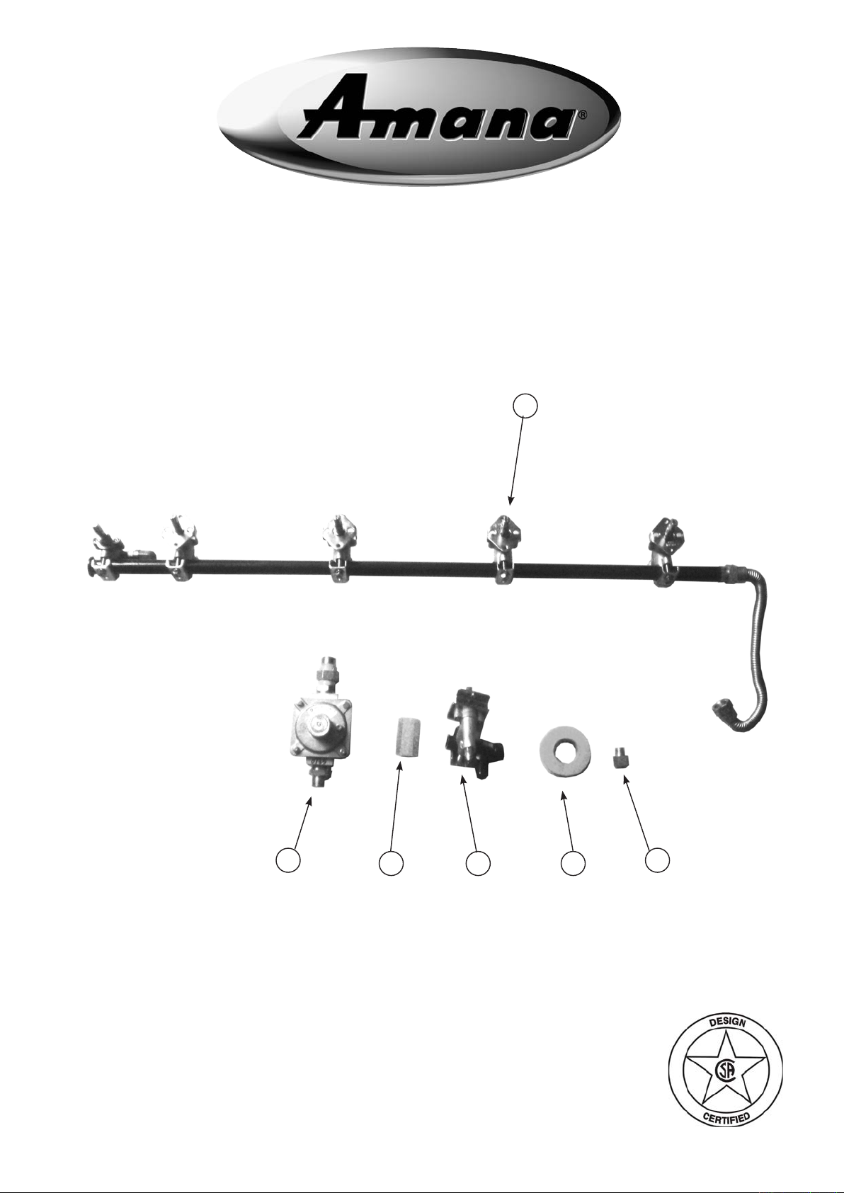
Part No. Qty Description
1 RCOZZ00339A 1 Main Burner Valve & Manifold Assembly with Valves (NG)
2 RCOZZ00340A 1 Side Burner Assembly (NG)
3 RPAZZ00002A 1 Thread Sealing Tape
4 RCOZZ00117A 1 NG Regulator 3/8” NPT x 3/8” UNF
5 RCODZ00026A 1 Orice Back IR (NG)
6 RCODZ00052A 1 Connecting tube 3/8" NPT
326
Page 2
AM33 LP-P Natural Gas Conversion Instructions
Tools needed:
Phillips head screwdriver
3/4” wrench
1/4” wrench or socket
Adjustable wrench
Wear golves to be protected from the sharp edges of the interior parts.
!
▲
NOTE: Make sure to use supplied pipe sealant on all non-ared ttings.
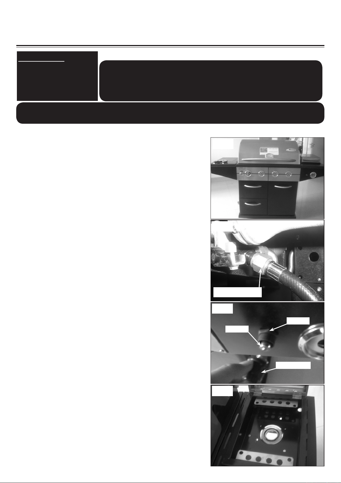
1. To get started, remove all the control knobs and set
aside. (See Fig. 1)
2. Use a 3/4” wrench to disconnect the regulator & hose
assembly from the side burner valve. (See Fig. 2)
Be sure gas supply is off, the knobs are in the off
position and the grill is cool.
!
WARNING
▲
Fig. 1
Fig. 2
3. Disconnect the igniter wires underneath the side burner
shelf. Then unscrew the push button cap on the side
burner shelf control panel, take out the battery and
unscrew the plastic nut to remove igniter module. (See
Fig. 3)
4. Remove the side burner griddle and side burner grate
(See Fig. 4)
Regulator hose
Fig. 3
Plastic nut
AA battery
Push button cap
Fig. 4
Page 3
AM33 LP-P Natural Gas Conversion Instructions
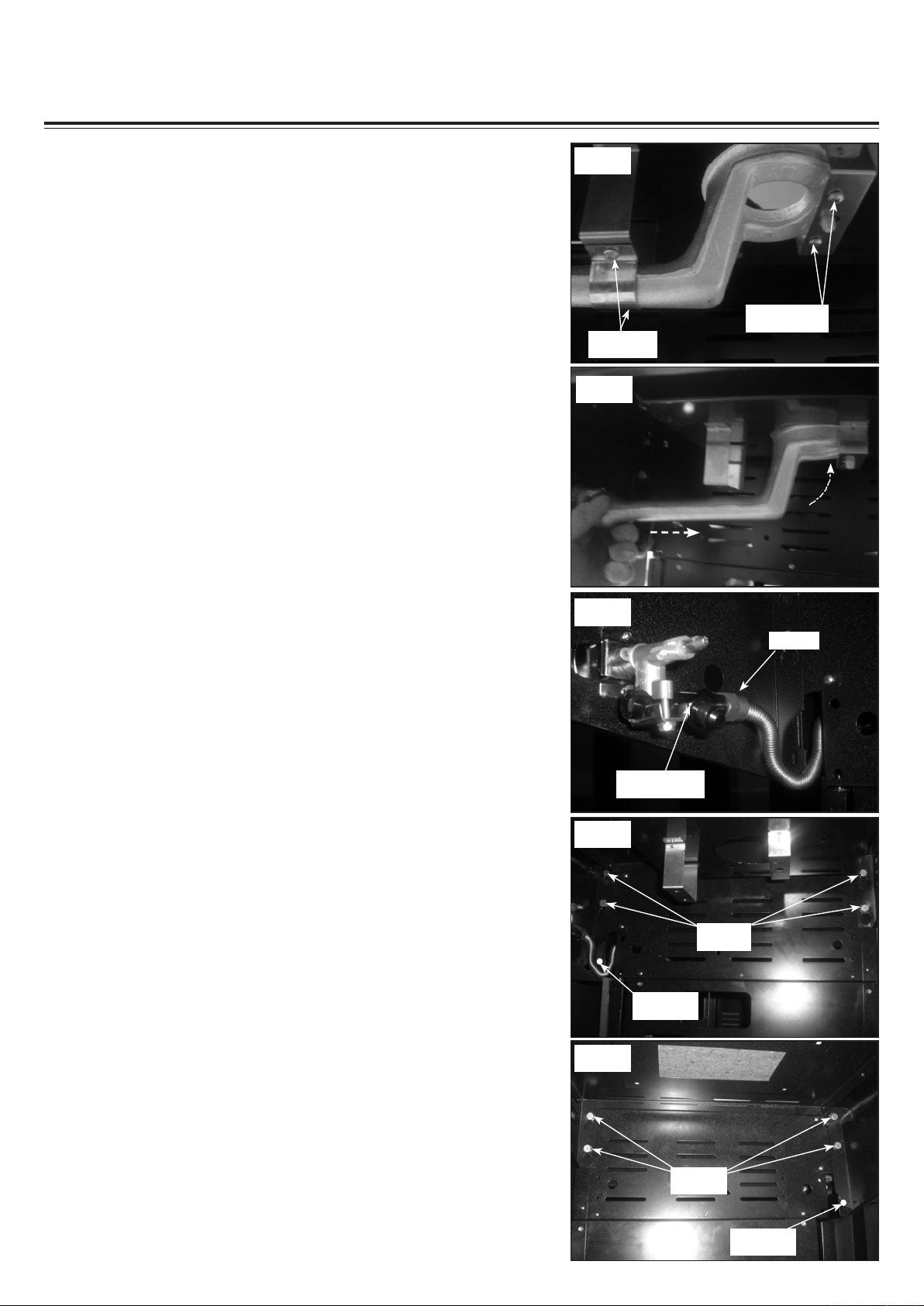
5. Remove the two phillips pan head screws and two self
-tapping screws securing the side burner casting and the
small bracket in position. (See Fig. 5)
6. Pull the side burner casting slightly to rear and angle it
up, then slide it into the hole on the side burner tray to
get the side burner valve orifice out of the side burner
casting. Remove it and set aside. (See Fig. 6)
Fig. 5
Self-tapping
Screws
Fig. 6
Phillips Pan
Head Screws
7. Disconnect the flex line from the side burner valve
assembly. (See Fig. 7)
8. Remove the self-tapping screw securing the right side
burner shelf in position. Loosen the four (4) hex head
screws on the right side of grill head assembly under the
side burner shelf for approximate 0.5” . Then lift and take
off the side burner shelf and set aside. (See Fig. 8)
9. Remove the self-tapping screw securing the left side
shelf in position. Loosen the four (4) hex head screws
on the left side of grill head assembly under the left side
shelf for approximate 0.5” . Then lift and take off the left
side shelf and set aside. (See Fig. 9)
Fig. 7
Flex line
Side burner
valve assembly
Fig. 8
Hex head
screws
Self-tapping
Screw
Fig. 9
Hex head
screws
Self-tapping
Screw
Page 4

AM33 LP-P Natural Gas Conversion Instructions
10. Remove the two (2) phillips pan head screws at the left
side of the the front control panel. (See Fig. 10)
11. Remove the two (2) phillips pan head screws at the right
side of the the front control panel. (See Fig. 11)
Fig. 10
Fig. 11
12. Let a friend help you to pull the front control panel away
from the grill and hold it. Using a wrench, hold the elbow
on the rear IR burner valve and use another wrench to
disconnect the ex line. (See Fig. 12)
13. Take off the front control panel, then use a screwdriver
to remove the eight (8) screws securing the bezels and
the manifold in position. (See Fig. 13)
14. Disconnect the ex line from the end of manfold. (See
Fig. 14)
Fig. 12
Fig. 13
Fig. 14
Page 5

AM33 LP-P Natural Gas Conversion Instructions
15. Replace the LP manifold with the one provided in the
NG conversion kit. Reattach the ex line to the manifold
and use the eight screws removed in step 13 to attach
the bezels and manifold onto the front control panel.
(See Fig. 15)
NOTE: Make sure the “ OFF” position facing up as
it was.
16. Attach the front control panel onto the grill assembly.
Hold the elbow on the rear IR burner valve and use a
3/4 wrench to tighten the ex line . (See Fig. 16)
Note: Be careful, applying pressure to the elbow of
the valve may cause it to break.
Fig. 15
Fig. 16
17. Slide the front control panel back in position. Make sure
the orices of the main burner control insert valves into
the main burner tubes. (See Fig. 17)
18. Use the four screws removed in step 10-11 to secure
the front control panel in position. (See Fig. 18)
19. Remove the bread warming rack, main cooking grates,
flavor grids and set them aside. Remove the six (6)
screws securing the wind shield and rear IR cover in
position. Remove the rear IR burner cover. (See Fig.
19)
Fig. 17
Main burner tube
Orice
Fig. 18
Fig. 19
Page 6

AM33 LP-P Natural Gas Conversion Instructions
Fig. 20
20. Hold the elbow and use a wrench to remove the rear IR
burner orifice. Replace it with the supplied NG orifice
and use the six screws removed in step 18 to secure the
rear IR burner cover and wind shield in position.(See
Fig. 20)
21. Remove the two (2) screws securing the bezel and
side burner valve in position on the right side shelf,
then remove the side burner valve. Replace it with the
supplied NG side burner valve and reattach the bezel
with the two (2) screws removed. (See Fig. 21)
NOTE: Make sure the “ OFF” position on the bezel
is facing up .
22. Attach the right side burner shelf by inserting the four (4)
screws on the right side of the grill head into the holes
on the right shelf. Then tighten all the four (4) screws
and install the self-tapping screw at the slotted hole on
the front bottom corner of the right side burner shelf.
(See Fig. 22)
23. Attach the left side shelf by inserting the four (4) screws
on the left side of the grill head into the holes on the
left side shelf. Then tighten all the four (4) screws and
install the self-tapping screw at the slotted hole on the
front bottom corner of the left side shelf. (See Fig. 23)
Fig. 21
Fig. 22
Fig. 23
24. Reattach the flex line from the manifold onto the side
burner valve assembly. (See Fig. 24)
Fig. 24
Page 7

AM33 LP-P Natural Gas Conversion Instructions
25. Reinstall the igniter module in position, feed "AA" battery
with negative end in rst. Connect the six igniter wires
into the six holes. (See Fig. 28)
Note: The igniter is designed in such a way that it
does not matter which terminal tab is used when
connecting igniter wires.
26. Angle the side burner casting and insert it into the center
hole of the side burner tray. (See Fig. 26)
(See Fig. 25)
Fig. 25
Fig. 26
27. Slide the side burner casting back in position to get the
side burner valve orifice into the side burner casting.
(See Fig. 27)
28. Use the removed two (2) phillips pan head screws in
step 5 to secure the side burner casting on the large
bracket. (See Fig. 28)
Fig. 27
Fig. 28
29. Use the removed two (2) self-tapping screws in step 5
to secure small bracket in position. (See Fig. 29)
Fig. 29
Page 8

AM33 LP-P Natural Gas Conversion Instructions
30. Attach the connecting brass tube onto the side burner
valve assembly. (See Fig. 30)
31. Attach the NG regulator to the brass fitting.(See Fig.
31)
Note: pay attention to arrow on the NG regulator
indicating direction of gas flow. The arrow should
point toward the grill.
Fig. 30
Fig. 31
Arrow on
the back of
regulator
32. Place the bread warmer, avor grids, side burner grate,
side burner griddle and main cooking grates back in
position, reattach all the knobs back in position. (See
Fig. 32)
Note: At the completion of the conversion, a leak test
should be performed on all ttings. See Use and Care
manual for leak testing procedure.
Installation is now complete.
Enjoy your grill safely.
Fig. 32
Conversion Kit Assembly Picture
 Loading...