

Page 1
SureFly Partners, LTD.
350 Howard Clemmons Rd.
Granbury, TX 76048
SureFly Tach2 Installation Instructions
SF2002, Revision IR
Page 1 of 8
Technical Support:
817-373-5161
M–F, 8:30a–4:30p, CDT
TACH2
INSTALLATION INSTRUCTIONS
Document No. SF2002, Revision IR
Revision History
Revision:
Date:
Description:
Approved
By:
IR
07/17/2020
Initial release.
RVC
Page 2

SureFly Partners, LTD.
350 Howard Clemmons Rd.
Granbury, TX 76048
SureFly Tach2 Installation Instructions
SF2002, Revision IR
Page 2 of 8
Technical Support:
817-373-5161
M–F, 8:30a–4:30p, CDT
Contents
Contents ................................................................................................................................................. 2
1. Installation Overview ...................................................................................................................... 3
1.1. General Description: ................................................................................................................... 3
1.2. Technical References: ................................................................................................................ 3
1.3. Compatible Electronic Tachometers: .......................................................................................... 3
2. Step-By-Step Installation Instructions ............................................................................................ 4
2.1. Mounting the Tach2 Unit: ............................................................................................................ 4
2.2. Wiring the Tach2 Unit: ................................................................................................................ 4
3. Post-Installation .............................................................................................................................. 8
3.1. Final Inspection: .......................................................................................................................... 8
3.2. Operational Check: ..................................................................................................................... 8
3.3. Radio Interference Test: ............................................................................................................. 8
a) All Installed VHF COMM and NAV Radios (record frequencies utilized): ................................. 8
b) GPS (if installed): ........................................................................................................................ 8
c) Resolution: .................................................................................................................................. 8
4. Documentation ............................................................................................................................... 8
4.1. ICA: ............................................................................................................................................. 8
Page 3

SureFly Partners, LTD.
350 Howard Clemmons Rd.
Granbury, TX 76048
SureFly Tach2 Installation Instructions
SF2002, Revision IR
Page 3 of 8
Technical Support:
817-373-5161
M–F, 8:30a–4:30p, CDT
1. Installation Overview
1.1. General Description:
The Tach Signal Converter (Tach2) converts SIM P-Lead signals to negative –going signals compatible with
the Horizon P-1000 digital tachometer input and to a positive-going 0-5V square wave signal compatible with
electronic tachometers that rely on a signal from a magnetic pickup inserted into a magneto. Tach 2 can
accept one or two SIM P-Leads as input, converts and conditions the signals and outputs them to
corresponding output terminals.
The Tach2 must be installed in the aircraft cabin and secured to the airframe with screws and nuts.
The Tach2 power input from the aircraft bus may range from 8.5VDC to + 30VDC without damage.
The Tach2 consumes less than 0.25A of power.
1.2. Technical References:
The following documents may be referenced during the installation of the Tach2:
1. SureFly Tach2 Installation Instructions: SF2002 (this document),
2. FAA Advisory Circular 43.13-1b Acceptable Methods, Techniques, and Practices.
Copies of these documents may be found at www.surefly.aero/airframe
1.3. Compatible Electronic Tachometers:
Compatible electronic tachometers are:
1. P-Lead signals negative-going compatible with the Horizon P-1000 digital tachometer input,
2. P-Lead signals positive-going 0-5V square wave signal that previously relied on a signal from a
magnetic pickup inserted into a magneto.
Page 4
SureFly Partners, LTD.
350 Howard Clemmons Rd.
Granbury, TX 76048
SureFly Tach2 Installation Instructions
SF2002, Revision IR
Page 4 of 8
Technical Support:
817-373-5161
M–F, 8:30a–4:30p, CDT
2. Step-By-Step Installation Instructions
2.1. Mounting the Tach2 Unit:
Select a location in the aircraft cabin to mount the unit. Secure the Tach2 to the mounting surface with
screws, washers and nuts per AC43-13.
2.2. Wiring the Tach2 Unit:
The Tach2 must be installed using MIL-W-22759 Tefzel insulated wire. All wires must be AWG20 or larger.
Crimp the provided AMP 31890 ring terminals onto the end of the wires that attach to the Tach2 barrier strip.
Route the interconnecting wires in such a manner as to avoid strain or chafing.
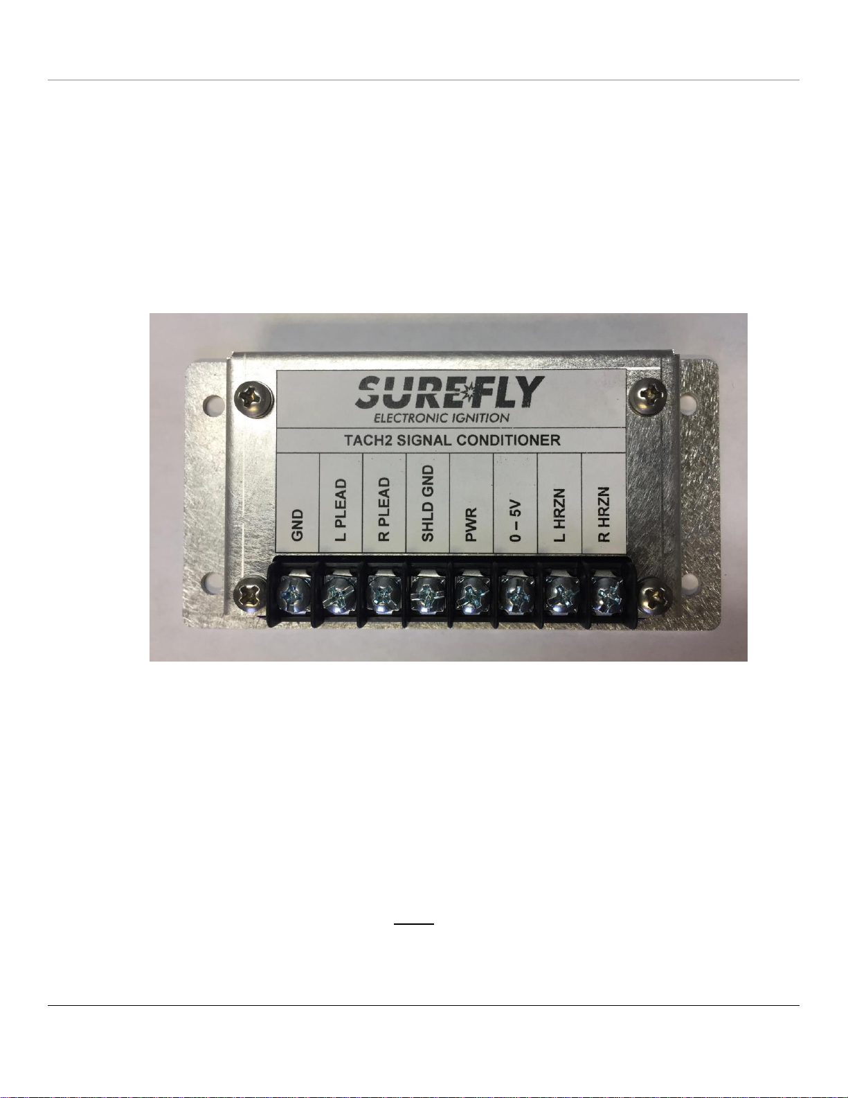
Tach 2 is contained in a small metal enclosure with connections made via screw-terminals in a barrier strip:
The connections available on the terminal strip of Tach2 are:
1. GND - Airframe ground.
2. L Plead* - Connect the P-Lead of a SIM on the left of the engine to this terminal.
3. R Plead* – Connect the P-Lead of a SIM on the right of the engine to this terminal.
4. SHLD GND - Connect the P-Lead shield a shield exists) to this terminal.
5. PWR - Connect this terminal to a power circuit protected by an appropriate circuit protection device.
The same power source as the existing, previously installed, electronic tach instrument which the
Tach2 is to be connected is recommended. This may be a Horizon P-1000, a Garmin EFIS, etc.
6. 0-5V – Square wave output. Connect to signal input of the electronic tach or EFIS that requires a 05V square wave.
7. L HRZN - For SIM on the Left, connect this terminal to the Horizon left P-lead input.
8. R HRZN - For SIM is on the Right, connect this terminal to the Horizon right P-lead input.
* The L Plead and R Plead terminals connect ONLY to the P-Lead terminal of an installed SIM. They are
not to be connected to a magneto.
Page 5

SureFly Partners, LTD.
350 Howard Clemmons Rd.
Granbury, TX 76048
SureFly Tach2 Installation Instructions
SF2002, Revision IR
Page 5 of 8
Technical Support:
817-373-5161
M–F, 8:30a–4:30p, CDT
Connect Terminal 1 (GND) to an appropriate airframe ground such as one of the Tach2 mounting screws.
Connect Terminal 2 (L Plead) to the P-Lead terminal of a SIM installed in the left position on the engine or to
the corresponding terminal on the ignition switch.
Connect Terminal 3 (R Plead) to the P-Lead terminal of a SIM installed in the right position on the engine or
to the corresponding terminal on the ignition switch.
Terminal 4 provides a convenient place to ground the shields of the P-Leads, if such exist.
Connect Terminal 5 (PWR) to the aircraft bus through an existing circuit protective device of a low enough
rating to protect the wire size used. The source of power used for the digital tach device is recommended.
The Tach2 draws less than .25A of power.
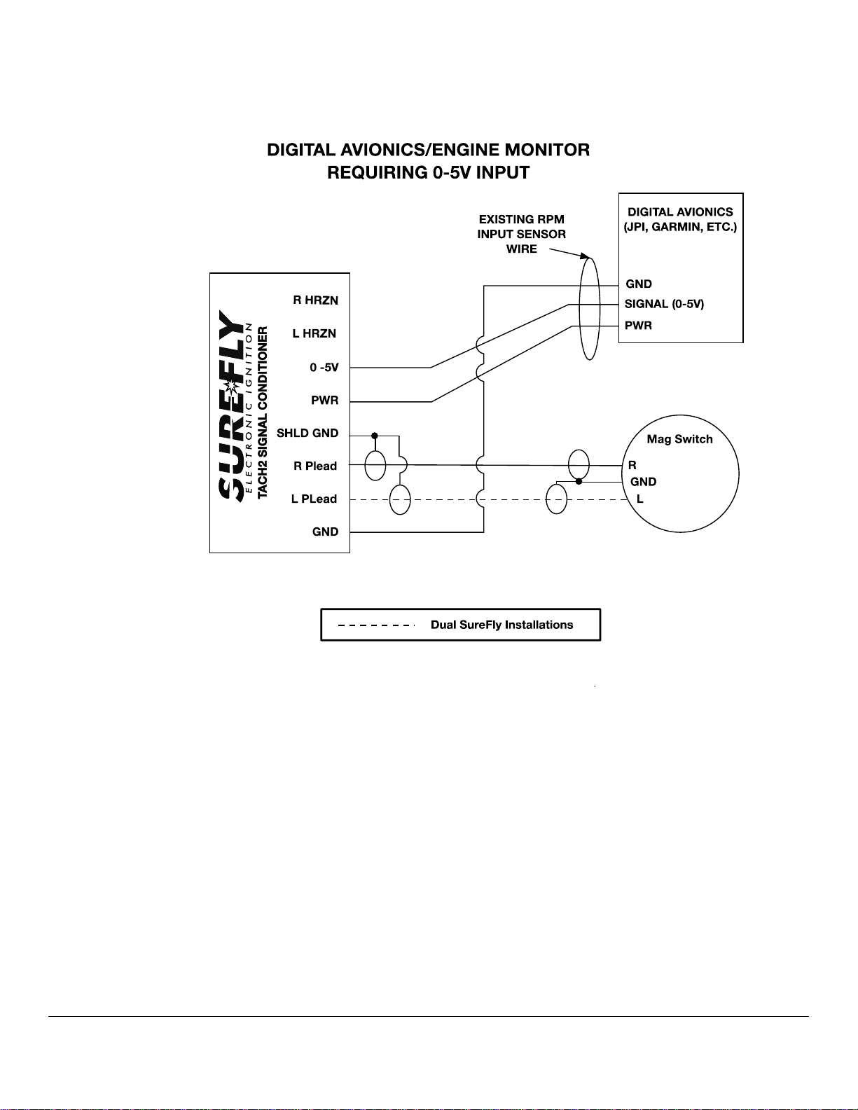
Connect Terminal 6 (0-5v) to the 0-5V input of an installed digital tachometer or EFIS (JPI, etc) that is
compatible with this signal level.
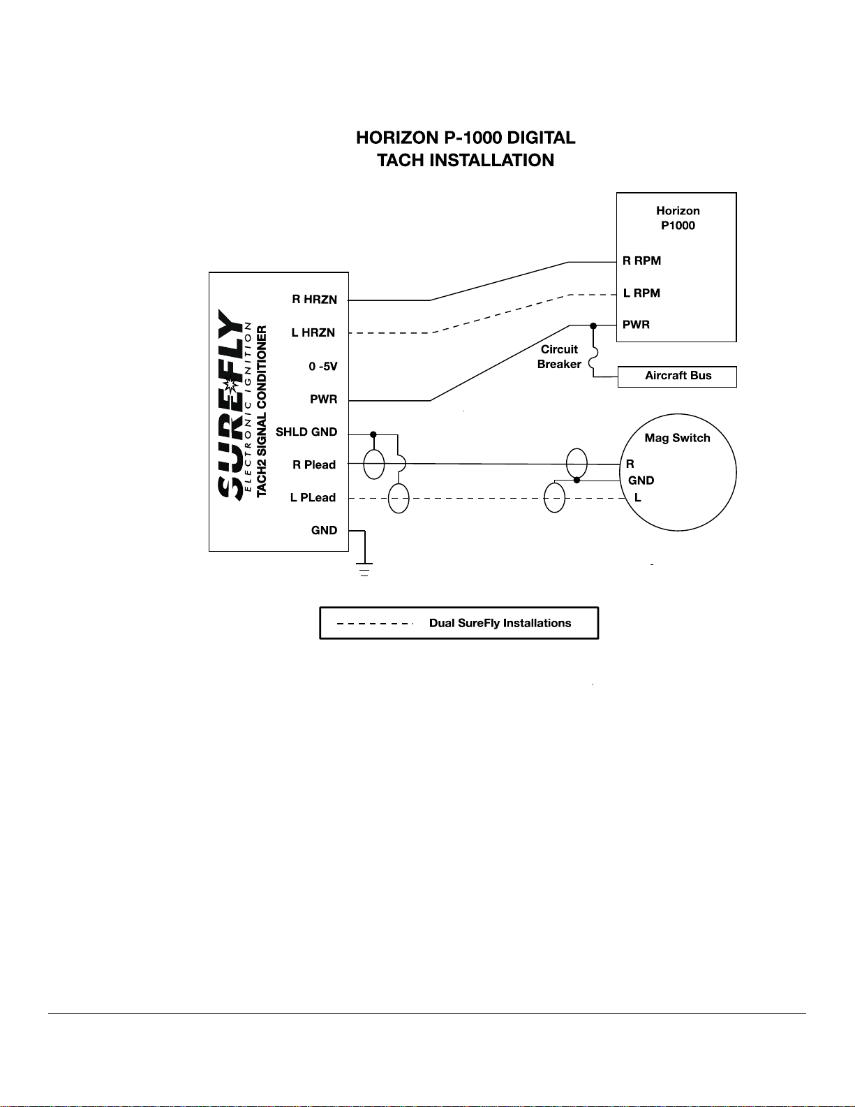
Connect Terminal 7 (L HRZN) to the L Plead input of an installed Horizon P-1000 digital tachometer if this
input of the Horizon was previously connected to a magneto that has been replaced with a SureFly SIM.
Connect Terminal 8 (R HRZN) to the R Plead input of an installed Horizon P-1000 digital tachometer if this
input of the Horizon was previously connected to a magneto that has been replaced with a SureFly SIM.
Page 6
SureFly Partners, LTD.
350 Howard Clemmons Rd.
Granbury, TX 76048
SureFly Tach2 Installation Instructions
SF2002, Revision IR
Page 6 of 8
Technical Support:
817-373-5161
M–F, 8:30a–4:30p, CDT
Page 7
SureFly Partners, LTD.
350 Howard Clemmons Rd.
Granbury, TX 76048
SureFly Tach2 Installation Instructions
SF2002, Revision IR
Page 7 of 8
Technical Support:
817-373-5161
M–F, 8:30a–4:30p, CDT
Page 8
SureFly Partners, LTD.
350 Howard Clemmons Rd.
Granbury, TX 76048
SureFly Tach2 Installation Instructions
SF2002, Revision IR
Page 8 of 8
Technical Support:
817-373-5161
M–F, 8:30a–4:30p, CDT
3. Post-Installation
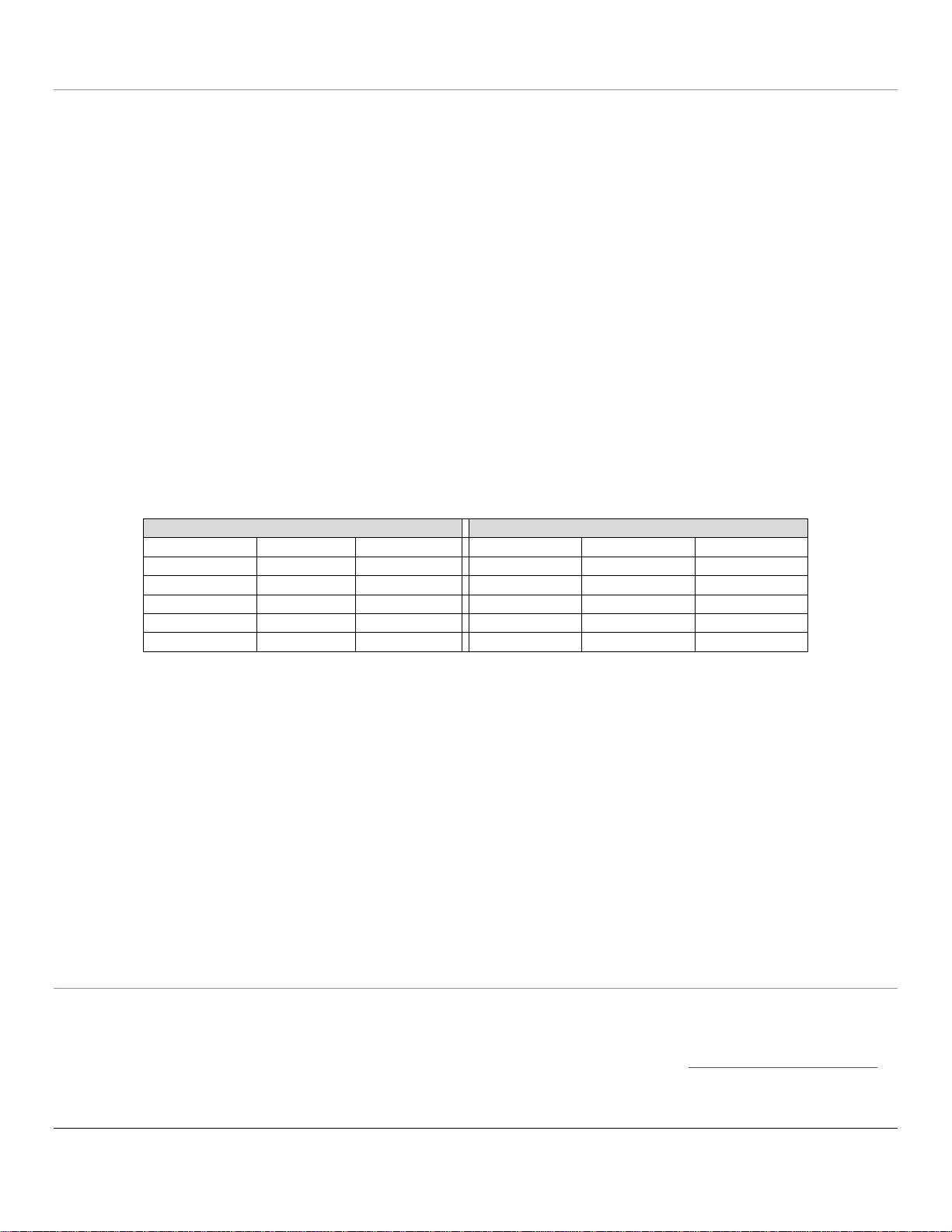
VHF COMM Receiver A:
VHF COMM Receiver B:
118.00 MHz
124.00 MHz
130.00 MHz
118.00 MHz
124.00 MHz
130.00 MHz
119.00 MHz
125.00 MHz
131.00 MHz
119.00 MHz
125.00 MHz
131.00 MHz
120.00 MHz
126.00 MHz
132.00 MHz
120.00 MHz
126.00 MHz
132.00 MHz
121.00 MHz
127.00 MHz
133.00 MHz
121.00 MHz
127.00 MHz
133.00 MHz
122.00 MHz
128.00 MHz
134.00 MHz
122.00 MHz
128.00 MHz
134.00 MHz
123.00 MHz
129.00 MHz
135.00 MHz
123.00 MHz
129.00 MHz
135.00 MHz
3.1. Final Inspection:
a) Visually inspect the following items:
1. Power wire is connected and secure at both ends,
2. Ring terminals are correctly crimped at both ends of the power wire,
3.2. Operational Check:
After installation, start the engine and perform a normal magneto check, verifying that the tachometer shows
engine RPM as normal.
3.3. Radio Interference Test:
a) All Installed VHF COMM and NAV Radios (record frequencies utilized):
Record frequencies where induced audio noise is present (if any).
If interference or abnormal operation is detected, remove power from Tach2.
If interference or abnormal operation goes away, there is likely interference from the Tach2.
If interference or abnormal operation persists with the Tach2 OFF, the cause may be interference from other
devices or faulty aircraft systems.
Continue to next section.
b) GPS (if installed):
Verify that the GPS acquires satellite position with the Tach2 operating.
If satellite acquisition is abnormal, turn the Tach2 OFF.
If abnormal operation goes away, there is likely interference from the Tach2.
If abnormal operation persists with the Tach2 OFF, the cause may be interference from other devices or
faulty aircraft systems.
Continue to next section.
c) Resolution:
If Tach2 caused interference is found, reinstall with shielded wires on P-Lead connections and Retest.
4. Documentation
4.1. ICA:
a) The Instructions for Continued Airworthiness for the Tach2 may be found at www.surefly.aero/airframe
 Loading...