

Page 1
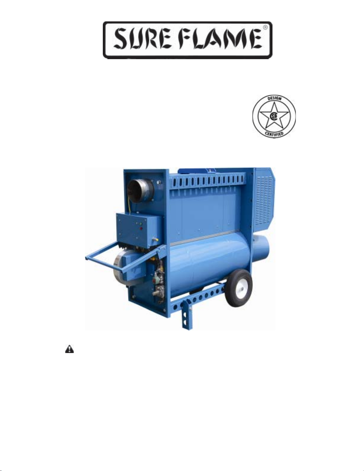
Operation and Maintenance Manual
Model No. IX405
Indirect Construction Heater
400,000 Btu/h
W ARNING
Read and follow all installation, and operating
instructions before first use of this product
Retain these instructions for future reference
Sure Flame Products
A Divison of Haul-All Equipment
4115 - 18 A venue North
Lethbridge, Alberta T1H 5G1
www.sureflame.ca
P/N 974-1184
Rev 1.0 Nov 14, 2011
Page 2
IX405 Operation & Service Manual
GENERAL HAZARD WARNING
Failure to comply with the precautions and
instructions provided with this heater , can result in
death, serious bodily injury and property loss or
damage from hazards of fire, explosion, burn,
asphyxiation, carbon monoxide poisoning, and/or
electrical shock.
Only persons who can understand and follow the
instructions should use or service this heater .
If you need assistance or heater information such
as an instruction manual, labels, etc. Contact the
manufacturer.
WARNING
Fire, burn, inhalation, and explosion hazard. Keep
solid combustibles, such as building materials,
paper or cardboard, a safe distance away from the
heater as recommended by the instructions. Never
use the heater in spaces which do or may contain
volatile or airborne combustibles, or products such
as gasoline, solvents, paint thinner , dust particles or
unknown chemicals.
WARNING
Not for home or recreational vehicle use.
2
P/N 794-1 184 Rev: 1.0
Page 3
IX405 Operation & Service Manual
Read this Warning First
This heater is designed and approved for use as a construction heater under ANSI Z83.7a-
. The primary purpose of construction heaters is to provide temporary heating of buildings
2007
under construction, alteration, or repair and to provide temporary emergency heat. Properly
used, the heater provides safe economical heating. Since the products of combustion are
released, it is imperative that the flue stack is extended outside of the enclosed area when the
heater is positioned indoors.
This heater is not designed as an Unvented Gas Fired Room Heater under ANSI-Z21.1 1.2 and
should not be used in the home. ANSI A1 19.2(NFP A 501C)-1987 Recreational V ehicle
St andard prohibits the installation or storage of LP-Gas containers even temporarily inside any
recreational vehicle. The standard also prohibits the use of Unvented Heaters in such vehicles.
Installation must comply with local codes, or in the absence of local codes, with the
National Fuel Gas Code ANSI Z223.1/NFPA 54 and the Standard for the Storage and
Handling of Liquified Petroleum Gases ANSI/NFPA 58.
We cannot anticipate every use which may be made for our heaters.
CHECK WITH YOUR LOCAL FIRE SAFETY AUTHORITY IF YOU HA VE QUESTIONS ABOUT
LOCAL REGULA TIONS.
Other standards govern the use of fuel gases and heat producing products in specific
applications. Y our local authority can advise you about these
Table of Contents
Specifications.................................................................................... 4
Installation.......................................................................................... 5
Installation Using A Propane Supply Tank..................................................6
Installation For Natural Gas Applications...................................................7
Operating Instructions ........................................................................ 8
Maintenance...................................................................................... 10
Troubleshooting Chart........................................................................ 11
Wiring Diagrams ............................................................................... 14
Parts Diagrams ................................................................................. 15
P/N 794-1 184 Rev: 1.0
3
Page 4
IX405 Operation & Service Manual
SPECIFICATIONS
Model No. IX405
Capacity: 400,000 Btu/h (120 kW)
Gas: Natural or Propane
Inlet Pressure*: max 14” WC (3.5kPa)
min 1 1” WC (2.75 kPa)
Manifold Pressure: Natural Gas 5.6”WC (1.4 kPa)
Propane 2.8”WC (0.7 kPa)
Orifice Size: 9/64” (x7)
Electrical Rating: 120 volts, 12A, 1Ph, 60 Hz
Minimum Temperature: -30°C (-22°F)
Duct Diameter: 16” or 2 x 12”
Maximum Duct Length: 32’ (9.8 m)
Venting: Category I
Fuel Consumption: Natural Gas 5.6”WC (1.4 kPa)
Propane 2.8”WC (0.7 kPa)
Certification: ANSI Z83.7a-2007
* Minimum inlet pressure is for purpose of input adjustment
4
P/N 794-1 184 Rev: 1.0
Page 5
IX405 Operation & Service Manual
Installation
The Sure Flame Model IX405 is an indirect-fired gas heater intended to be used primarily for
the temporary heating of buildings under construction, alteration or repair . Since the products
of combustion are released, it is imperative that the flue stack is extended outside of the
enclosed area when the heater is positioned indoors. The flow of supply air and exhaust
gasses must not be obstructed in any manner.
The equipment shall be installed in accordance with the Natural Gas and Propane Installation
Code CSA B149.1, and applicable local regulations, which should be carefully followed in all
cases. Authorities having jurisdiction should be consulted before inst allations are made.
The heater shall be used in a horizontal position on a firm, non-combustible surface.
The electrical grounding of the appliance shall be in compliance with the CSA C22.1,
Canadian Electrical Code, Part I
Warning: The installation and maintenance of the heater must be accomplished by a qualified
service person. The heater should be inspected before each use and at least annually .
Warning: Do not use this heater in a space where gasoline of other liquids with flammable
vapours are stored or used
Clearances
Clearance required for combustibles:
Outlet: 10 ft (3 m)
Sides: 2 ft (0.6 m)
To p: 3 ft (0.9 m)
Flue: 18” (45 cm)
Floor: Noncombustible
Minimum clearance required to LP Gas containers:
Outlet: 20 ft (6.0 m)
Top & Sides: 10 ft (3.0 m)
Position heater properly on a horizontal surface before use.
The hose assembly shall be protected from traffic, building materials and contact with hot sur-
faces both during use and while in storage. For use with or without ductwork. Only ductwork
supplied by the manufacturer shall be used with this heater. For either indoor or outdoor use.
Adequate ventilation must be provided. This heater is for operation at a temperature rise from
80°C to 140°C (175°F to 285°F).
All gas inspection authorities in Canada require that the installation and maintenance of heaters
and accessories shall be accomplished by qualified gas fitters.
Installation must comply with the Natural Gas and Propane Installation Code, CSA B149.1.
Ducting
The IX405 can be ducted on both the inlet and outlet. The inlet duct can be up to 50' of smooth
16" metal duct The outlet duct shall be of a material able to withstand temperatures of up to
450F. Total outlet duct length may be up to 300' of straight, smooth, 16" metal duct Use of
flexible ducts, smaller ducts, or bends in the ducts will reduce the allowable length and may result
in excessive cycling of the burner.
P/N 794-1 184 Rev: 1.0
5
Page 6
IX405 Operation & Service Manual
Venting
This equipment requires CLASS A venting to the exterior . The vent connector should be
designed for a negative pressure and be constructed of materials having corrosion resistance
and durability to heat at least equivalent to that of No. 24 GSG galvanized steel.
Venting must comply with the Natural Gas and Prop ane Installation Code CSA B149.1, as well
as other local regulations that may apply .
Flue Diameter 8" 6"
Min. vertical height 4' 4'
Max. lateral length* 15' 0'
Max. number of added elbows** 2 0'
*Lateral lengths must have a minimum 10% rise.
** A minimum vertical length of 2' is required before the first elbow and after the last elbow .
Consult the manufacturer for additional venting options.
Rated flue gas temperature 1000°F (540°C)
Rated vent pressure - Negative
Category I
Gas Connections
Ensure the correct regulator is used to supply the heater with maximum inlet pressure of 14”w.c.
Excessive pressure will damage components and void the warranty .
Visually inspect the fuel supply hose assembly . Ensure that it is protected from traffic, building
materials, and contact with hot surfaces. Replace if there is evidence of excessive wear or
abrasion.
After installation, check for gas leaks by applying a soapy solution at each piping and hose
assembly connection.
6
P/N 794-1 184 Rev: 1.0
Page 7
IX405 Operation & Service Manual
INSTALLATION USING A
PROPANE SUPPLY TANK
1 When installing the heater for use with propane gas, set the gas selector valve to “Propane”
and lock in position.
2 Arrange the propane supply system to provide for vapour withdrawal from the operating
container. Supplying liquid propane to the heater is dangerous and will damage the
components. Another regulator must be installed on the heater to reduce the pressure from
this regulator to a maximum inlet pressure of 1/2 psi.
3 Ensure that for the surrounding temperature the size and capacity of the propane supply
container is adequate to provide the rated Btu/h input to the heater.
4 Turn off the propane supply valve at the container when the heater is not in use.
5 The installation must conform with local codes, or in the absence of local codes, with the
Standard for the Storage and Handling of Liquedied Petroleum Gases, ANSI/NFPA 58.
6 When the heater is to be stored indoors the propane container must be disconnected from the
heater and the container moved away and stored in accordance with the above national
standards.
INSTALLATION FOR
NATURAL GAS APPLICATIONS
1 When installing the heater for use with natural gas, set the gas selector valve to the “Natural”
position.
2 A regulator must be installed on the heater to ensure that the pressure to the heater does not
exceed 1/2 psi inlet pressure.
3 The installation of this heater to a natural gas supply must conform with all applicable local
codes, or in the absence of local codes, with the National Fuel Gas Code ANSI Z223.1/
NFPA 54.
P/N 794-1 184 Rev: 1.0
7
Page 8
IX405 Operation & Service Manual
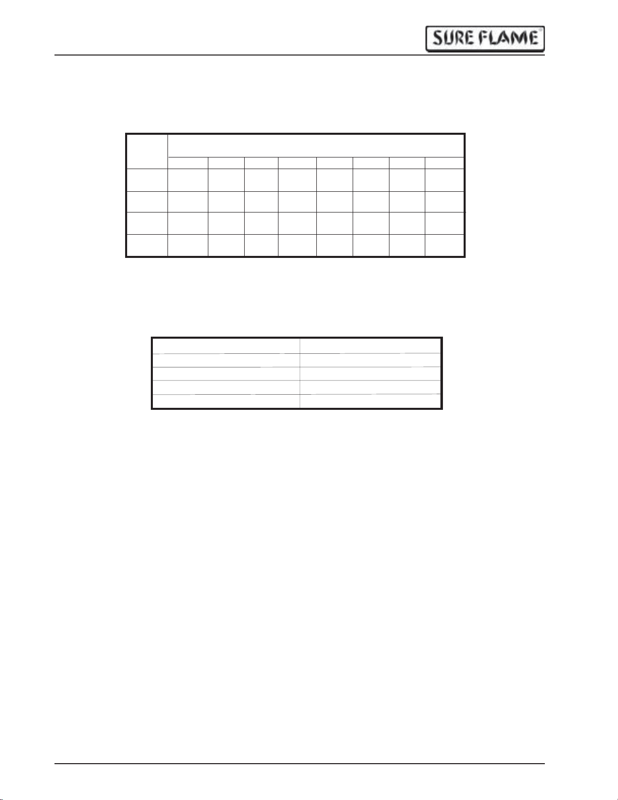
LPG - PROPANE FUEL VAPORIZATION RATE
The following chart shows the amount of BTU's that various sizes of tanks will produce on the average at specific
temperatures and regular atmospheric conditions.
Tank Size
Gallons
(Pounds)
150 214,900 187,900 161,800 148,000134,700132,400108,800107,100
(600)
250 288,100 251,800 216,800 198,400180,600177,400145,800143,500
(1000)
500 478,800 418,600 360,400 329,700300,100294,800242,300238,600
(2000)
1000 852,800745,600641,900587,200534,500 525,400 431,600 425,000
(4000)
Maximum intermittent withdrawal rate (BTU/hr) without tank frosting*
if lowest outdoor temperature (average for 24 hours) reaches.
+40 F. +30 F. +20 F. +10 F. 0 F. -10 F -20 F. -30 F.
* Frosting on the outside of the tank acts as an insulator, reducing the vaporization rate.
MAXIMUM BTU CONTENT (PROPANE)
The following table shows the maximum BTU's that a cylinder contains.
CYLINDER SIZE BTU CONTENT
100 pound 2,159,100
250 gallon USA 22,922,500
500 gallon USA 45,845,000
1000 gallon USA 91,690,000
CAUTION: In extremely cold weather it is impossible to completely empty a propane cylinder.
PRESSURE & FLOW EQUIVALENTS
1 Std. Atmosphere = 14.73 lb./sq. in. = 1.014 bar
1" Water Column (W.C.) = 0.58 oz./sq. in. = 2.49 millibar
11" Water Column = 0.4 lb./sq. in.= 27.39 millibar
1 lb./sq. in. (psig) = 27.71" W.C. = 0.0689 bar
1" Mercury = 0.49 psig = 33.86 millibar
1 Std. Cubic Ft./Hr. = 2,500 BTU/Hr. = 0.02832 cu. m/hr.
1 BTU/Hr. = 0.2931 Watts
8
P/N 794-1 184 Rev: 1.0
Page 9
IX405 Operation & Service Manual
Operating Instructions
1) Set GAS SELECTOR V AL VE to gas being used. The conversion shall only be done by the
owner or lessor of the equipment. NOTE: When using Propane Gas the Selector V alve must
be locked in position.
2) Ensure valve is in the "ON" position.
3) Connect Power - 120 volt supply .
4) Open gas supply .
5) Push "ST ART" button.
6) If equipped with a thermostat, set thermostat to desired temperature.
T o stop, push the "STOP" button and turn gas of f.
Warning: Blower may continue to cycle after heater is turned of f due to built up heat in the
combustion chamber. Do not stop the heater by unplugging. Heat accumulated in the heater
can shorten the life of components.
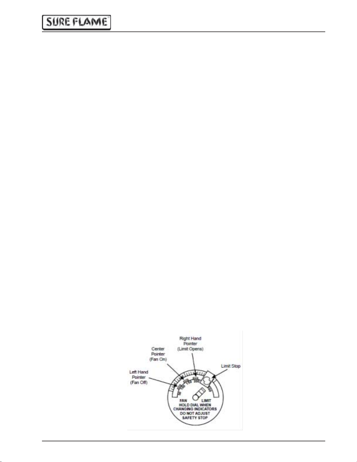
SETTING FAN LIMIT SWITCH
The fan limit switch is factory set and should not normally need to be adjusted. If it is out of
adjustment, follow these procedures:
T o set pointers, hold dial securely with one hand and move the pointers with the other hand. Do
not force the pointers past any stops on the dial even though the dial may be graduated
beyond the stops.
Limit
Move the right hand pointer so that its straight edge indicates 300°F.
Fan
Move the “Fan On” pointer so that its straight edge indicates 1 10°F . This is the temperature at
which the blower will start. Move the “Fan Off” pointer so that its straight edge indicates 90°F.
This is the temperature at which the blower will stop.
P/N 794-1 184 Rev: 1.0
9
Page 10
IX405 Operation & Service Manual
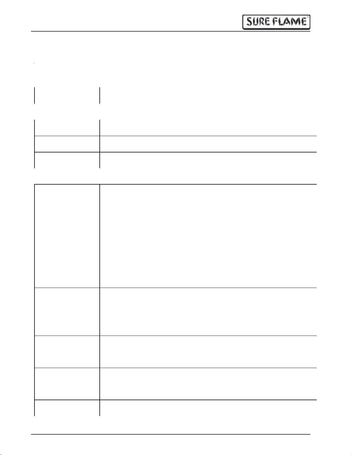
Maintenance
Warning: Disco nnec t ga s and electrical supplies before servic ing .
Weekly:
Gas Hose Check for cracks and damaged connectors
Air flow Remo ve any obs tructi ons to ai r flow
Monthly:
Cords and
Connectors
Physical Integrity Check for damage to body, louvers, and inlet screens that may obstruct air
Belt Replace belt if cracked or worn.
End of Season:
Combustion
Chamber
Burner Remove burn er from burn er assembly
Electrical
components
Valve Train Verify that manifold pressure matches the specification label. Adjust
Impellers Remove any dirt build-up on both burner and blower impellers.
Body Ensure all panels and shi elds are in pl ace and that fasteners are tight.
Check for cracks, exposed wires, and dirt in electr ical connectors
flow and i mpact comb ustion qua lity
Ensure belt tensioner is in place and tensioner roller is running smoothly.
Rem ove bu rn er assembly
Clean inside of combustion chamber with a wire brush. Vacuum all ash and
soot from combust ion chamber.
Inspect combustion chamber for any damage. Do not use a heater that has a
hol e in th e combustion chamber.
Clean flame rod and ignite r with solvent or emery cloth. Inspect for
cracked cerami c. Ensure they are properly centered in the burner openings
Inspect wires for cracks or evidence of overheating
Ensure burner head screws are tight.
Ensure openings in orifice plate (located inside the burner pipe) are not
blocked.
Ensure gasket and door seal are in place and not damaged.
Check al l wiring for loose, cracked, or overheated wires and connectors.
Replace if necessary.
Ensure ground wires are properly connected.
Ensure control box seal is in place and not damaged.
Wipe dirt from motors. Motors have sealed bearings and do not require
lubrication.
regu lato r pressu r e if necessar y.
Inspect strainer and clean if necessary.
Using soapy wat er or gas leak detector, check all gas connections for leaks.
Inspect impellers for loose or damaged fins.
Run heater and check for vibration.
Replace impellers t hat are damaged or causing vibration.
Inspect wheels for wear or excessive play in the bearings.
10
P/N 794-1 184 Rev: 1.0
Page 11
IX405 Operation & Service Manual
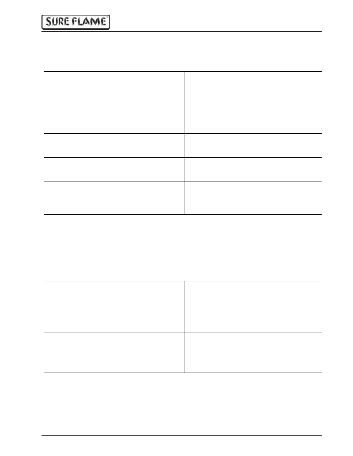
Heater Troubleshooting
Burner blower does not start, no spark, no flame
Symptom Possible Problems
No green light when Start Button is
pressed. No green light when manual
bu tt on on Log ic Relay is p ressed.
No green light when Start Button is
pressed. Green light comes on when
manual button o n Logic Relay is pressed.
Gr een light comes on when Start Button is
pressed, but turns off when button is
released
Green light is on. No err or light on Ignition
Control.
Green light is on. Sing le flas hes on Ignition
Control error light after 30 seconds.
Error light on Ignition Cont rol on steady Ignition Control failure
No electrica l supply
Fuse fa ilur e
Transformer failure
Start swit c h fa ilur e
Logic Relay failure.
Stop Switch failure
The r m os tat or Ju mp er Pl u g not installed.
Thermostat failure.
Fan Limi t Switch failure
Air Switch failure.
Bur n er Mot or f a ilu r e
Ignition Control failure
Burner blower starts, no spark, no flame
Symptom Possible Problems
Single flashe s on Ig nition Contr ol er ro r light
after 30 seco nds.
Three flashes on Ignition Cont rol error light. Igniter failure.
P/N 794-1 184 Rev: 1.0
Air Switch failure.
Air Switch s et t o too high a pressure.
Air tubes plugged or insert in wrong air
switch position.
Burner air inlet obstructed
Igniter shorting to ground.
Ignition transformer failure.
Loose ignition wire.
Ignition Control failure
11
Page 12
IX405 Operation & Service Manual
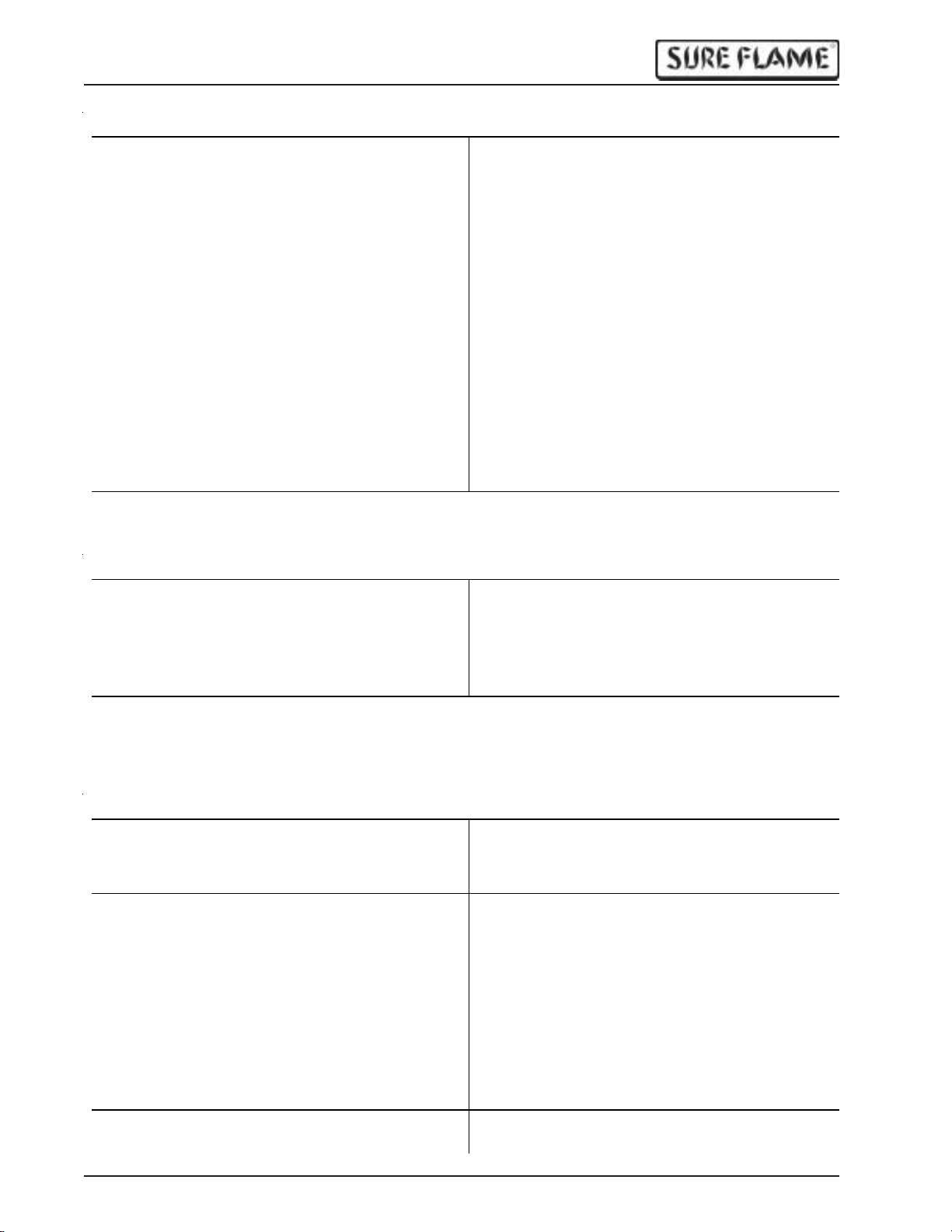
Burner blower starts, spark, no flame
Symptom Possible Problems
No cl ic k on So len oid V alv e a ft er 30 se cond
pre-purge. Three flashes on Ignition Control
error light.
Gas Valve clicks after 30 second prepurge. Three fl ashes on Ignit ion Control
error light.
Output Limit Switch failure
Exhaust Limit Switch failure
Blocked exhaust
Tilt Sw itch failu re
Solenoid Valve failure
Inl et pre ss ure too high
Igniter ceramic cracked
Ignition Control failure
Manual V alve clos ed
Gas Hose too long or too smal l
Burn er orific es plug ge d or d irty.
Strainer plugged or dir ty.
Manifold pressure set too low.
Gas Sele c tor Valve set to w ro ng fu el
Burner air inlet obstructed
Burner starts, but flame goes out after about 4 seconds
Symptom Possible Problems
Three flashes on Ignition Control error l ight. Loose Flame Rod or gr ound wire.
Flame Rod and Spark Plug wires reversed.
Flame Rod wet.
Ignition Control failure.
Burner starts, but main blower does not come on
Symptom Possible Problems
Blower M otor does not start when manua l
button on Bl owe r Relay is pr es sed.
Blower M otor turns on when ma nual butto n
on Blower Relay is pressed.
Blower Motor cannot accelerate to full
RPM. (excessive amperage draw). Circuit
Brea k er tri ps O FF dur ing B low er M otor
acce ler ation. H eater shuts off when Blower
Motor starts. Voltag e during Blower Mo tor
start up dropping under 100VAC.
Bl ow er Mo to r starts, but little or no air flo w . Bel t b r ok en
12
Blower M otor fa ilure
Blower Relay failure
Fan Limi t Switch failure
Fan Lim it Switc h se ttin gs inc orre ct
Low Volt age (long e xtensi on cord, too small
gauge of cord or too many items on circuit).
Poor quality power (such as fr om a
generator).
I mprop er voltage.
Wro ng Hert z.
Belt too tight
Motor connected in reverse
P/N 794-1 184 Rev: 1.0
Page 13
IX405 Operation & Service Manual
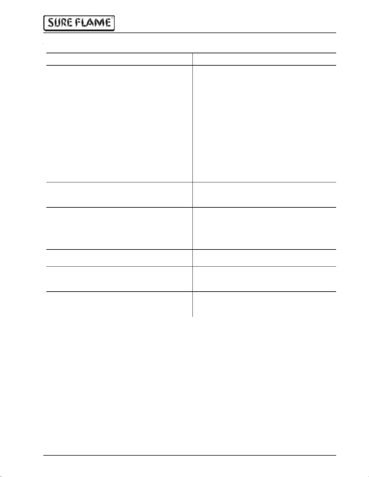
Other problems during operation
Symptom Possible Problems
Small or poor quali ty flame. Mani fold
pressure drops below rated value in
function. Heater ignites but may shut off
with three flashes on Ignition Control error
light.
Heater shuts off unexpectedly with three
flashes on Ignition Control error light.
Bu rne r cycle s on and o ff freq ue nt ly Fan Lim it Switc h se ttin gs in c orre ct
Excessive yellow flame. Rumbling noise
during flame ignition.
Heat er does not s top when Stop Button is
pressed
Excessive noise or vibration Damaged or unbalanced Burner Impeller
Blower Motor runs constantly. Blower Relay failure
Heater does not turn off when the rmostat
turned to minimum. No lights on Ignition
Control
Heater does not turn off when the rmostat
turned to minimum. Two flashes on Ignition
Control error light
Propane tank too small to vaporize fast
enough, tank freezes.
Gas Hose too small, too long, or blocked.
Inl et pre ss ure too low
Gas Sele c tor Val ve set to w ro ng fu el
Burner air inlet obstructed
Blocked exhaust
Flame rod failure
Out of fuel
Solenoid Valve failure
Output limit switch failure
Ignition Control failure
Duct s too long, too smal l, or obstruct ed
Gas Sele c tor Val ve set to w ro ng fu el
Heat er c onnected to liquid p rop ane supp ly
Manifold pressure set too high
Stop Switch failur e
Start Switch failure
Logic Relay failure
Damaged o r unbalanced Bl owe r Impe ller
Fan Limit Switch set in manual position
Thermostat failure
Solenoi d valve stuck o pen.
Solenoi d valve lea king
P/N 794-1 184 Rev: 1.0
13
Page 14
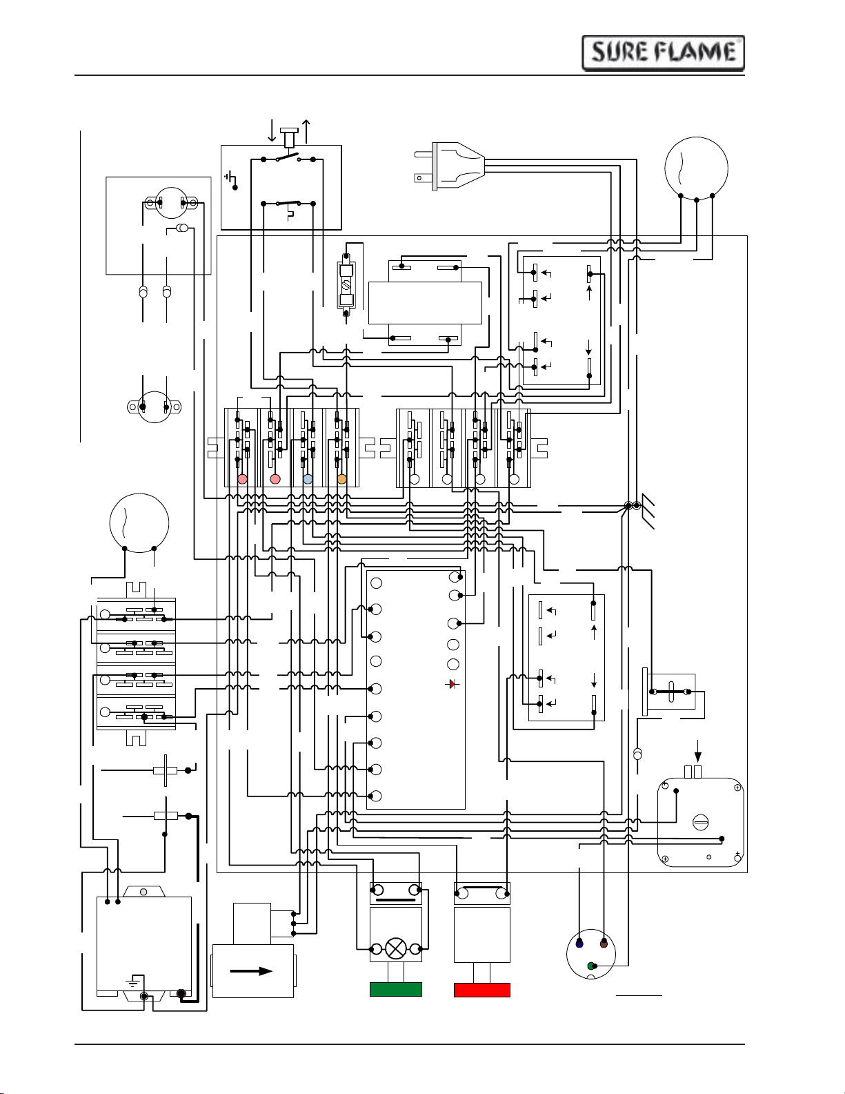
IX405 Operation & Service Manual
N
o
t
e
:
A
l
l
w
i
r
e
s
1
8
G
a
S
T
R
R
T
E
W
6
0
0
V
u
n
l
e
s
s
o
t
h
e
r
w
i
s
e
s
p
e
c
i
f
i
e
d
.
B
L
K
T
A
N
B
L
U
G
R
N
L
i
m
E
x
i
t
h
S
a
w
u
s
i
t
t
c
h
L
i
m
O
i
t
u
S
t
p
w
u
i
t
t
c
h
B
u
r
n
e
r
M
o
t
o
r
N
M
IT
FR
Flame
Rod
Igniter
Ignition
Transformer
B
L
K
R
E
D
H
i
T
e
m
p
M
M
a
n
u
a
l
L
F
I
A
N
N
E
G
N
H
i
L
i
W
H
T
R
E
D
H
i
T
e
m
W
p
H
T
H
i
L
i
D
L
L
I
I
M
N
I
E
T
B
L
U
B
B
L
K
R
N
PNK
A
u
t
o
F
a
n
L
F
O
L
A
A
N
i
D
m
i
t
S
w
L
L
i
O
I
t
M
c
A
I
D
T
h
F
u
B
s
L
e
K
2
A
G
R
N
B
/
Y
R
E
N
L
B
R
N
PNK
PNK
COM
Transformer
24VAC
WHT
120VAC
B
L
K
1
B
4
L
G
K
a
14/3 SJTW
BLK 14Ga
WHT 14Ga
2
4
W
H
T
1
4
G
6
a
8
B
0
N
L
O
O
W
C
E
R
O
R
I
B
E
L
L
L
A
N
Y
O
K
1
B
l
o
w
M
e
r
M
o
t
o
r
WHT 14Ga
I
W
H
T
G
R
N
G
R
N
X
4
1
0
W
I
R
I
N
G
S
G
W
H
T
H
i
T
e
m
p
G
I
N
N
G
D
P
N
R
K
E
D
G
R
N
1
4
G
a
H
V
Gas Solenoid
G
R
E
D
W
B
L
H
U
T
BLK
ORG
RED
P
N
K
COM
M
G
2
4
P
W
H
T
B
R
N
R
E
D
1
2
3
4
5
B
R
N
6
Y
E
L
7
8
9
C
START
BLK
S1-(240)
S1-(120)
L1(120V)
L2
S2/FS(FR)
PSW
W(TH)
MV1(gas)
B.GND
N O
H
L
R(24V)
NO
F
L
F
1
+
F
2
1
0
F
C
+
&
F
C
-
E
R
L
E
R
D
O
R
F
E
N
W
A
L
3
5
-
6
6
PRL
C
N C
STOP
N
L
GRN
GRN
B
B
B
L
R
U
N
B
R
N
R
E
D
NC
L
U
PNK
2
4
6
8
(OUTPUT)
BLK
N
O
N
O
3 - BLUE
0
L
O
G
C
I
C
O
R
E
I
L
L
A
Y
1
B
L
U
Thermostat
Plug
1 - GREEN
(GROUND)
G
R
N
2 - BROWN
(24VAC SUPLY)
FRONT VIEW
G
r
o
u
n
d
S
c
r
e
w
D
I
A
G
R
A
M
G
R
N
T
i
l
t
S
w
i
t
c
BLK
R
E
D
h
+
_
C
S
O
P
W
M
N
C
A
I
I
T
R
C
H
N
2
O
1
14
P/N 794-1 184 Rev: 1.0
Page 15
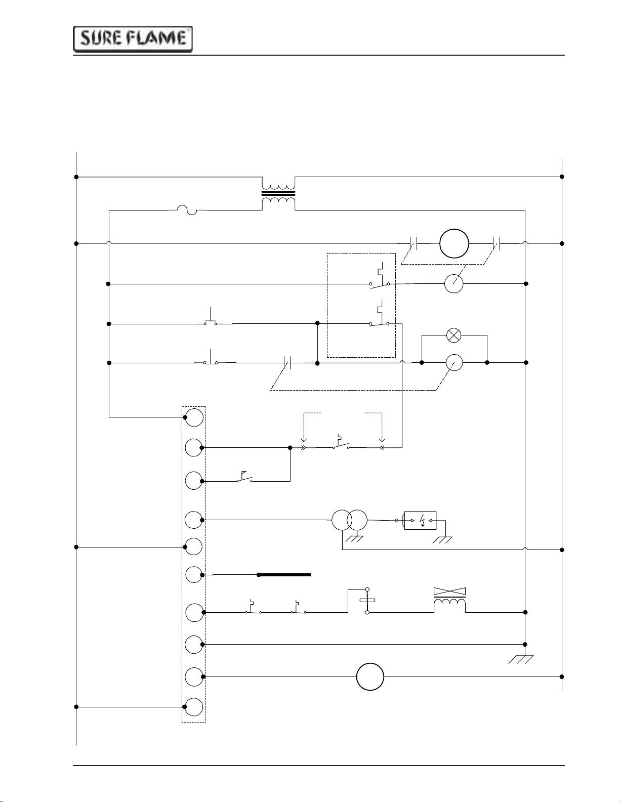
Ladder Diagram
IX405 Operation & Service Manual
L1
C
A
V
4
2
Thermostat Signal
Input (24VAC)
Air Pressure
Switch IN
Power OUT
Igniter
Fuse
Start Switch
C
Stop Switch
R
W
P.Sw
S1
L1
NO
NO
NCC
NC
Gas Controler Supply
Power (24VAC)
Air Pressure Sw.
COM 2
NO
Igniter
Power IN
COM120V
24VAC
Logic Relay
(contacts)
68
120/24VAC
Transformer
Jumper Plug
Thermostat
Blower Relay
Blower Control
Switch
NO
Burner Limit
Switch
NC
Fan/Limit Switch
Ignition
Transformer
contact
23
Blower Motor
86
NO
Igniter
M
Blower
Relay Coil
X1 X2
Logic
RelayCoil
N
Blower Relay
contact
42
NO
01
Power ON Lamp
(Start Button)
01
Flame Rod
Signal
Valve Power
OUT (24VAC)
Burner
Ground
Burner Motor
Power OUT
P/N 794-1 184 Rev: 1.0
F S
MV1
GND
F2
F1
Output Limit
Burner Motor
Power IN
NC
Switch
Flame Rod
NC
Exhaust Limit
Switch
NC
Tilt Switch
M
Burner Motor
M
Gas Valve Solenoid
(24VAC)
COM
15
Page 16
IX405 Operation & Service Manual
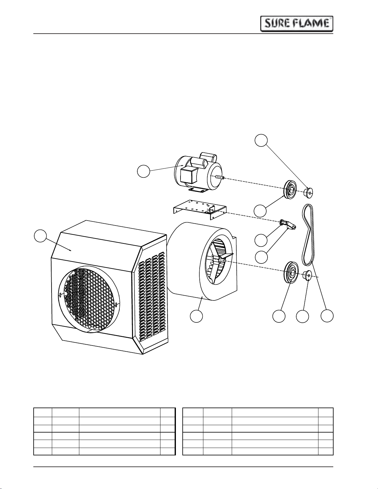
Parts Breakdown
Main Blower
3
2
1
7
4
5
6
8
9
10
Ref # P a rt # De s cri p tio n Q ty Ref # P a rt # D esc ri p ti on Q ty
1 IX-5 526
2 1460
3 6133
4 7747
5 1271
16
Blower Shroud Weldment
Motor 1 HP
Motor B ush ing Sp lit Tape r
Motor She a v e
B elt Tens ioner
1 6 1270
1 7 1272
1 8 1183
1 9 7750
1 10 1166
Tensioner Roller
Blower Assembly
Blower Sheave
Bushing S plit Taper H-3/4"
Belt
P/N 794-1 184 Rev: 1.0
1
1
1
1
1
Page 17
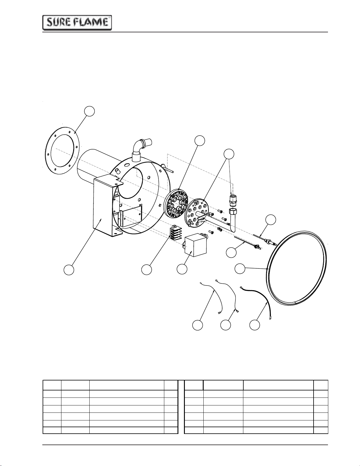
IX405 Operation & Service Manual
5
6
Burner
9
8
7
6
5
11
4
12
Bur ner Pip e Assembly 1
Burner Head
Burner Gas ket
Flame Rod Wire
B u rne r Gro u n d wire
Ig nition W ire
1
1
1
1
1
1
2
3
10
Ref # Part # D es c rip tion Qty Ref # Part # De s cripti on Qty
1 IX-3533
29823
3
8676 Ignition Transformer
4 7724 Flexible Seal 3.3' 10 W R9RDE-26
5130
6130
Burner Housing
Terminal Block
Flame Rod
Ig niter
17
18IX-3157
19IX-3198
1 11 WR9GER-30
1 12 WRIBEX-22
IX -3732
P/N 794-1 184 Rev: 1.0
17
Page 18
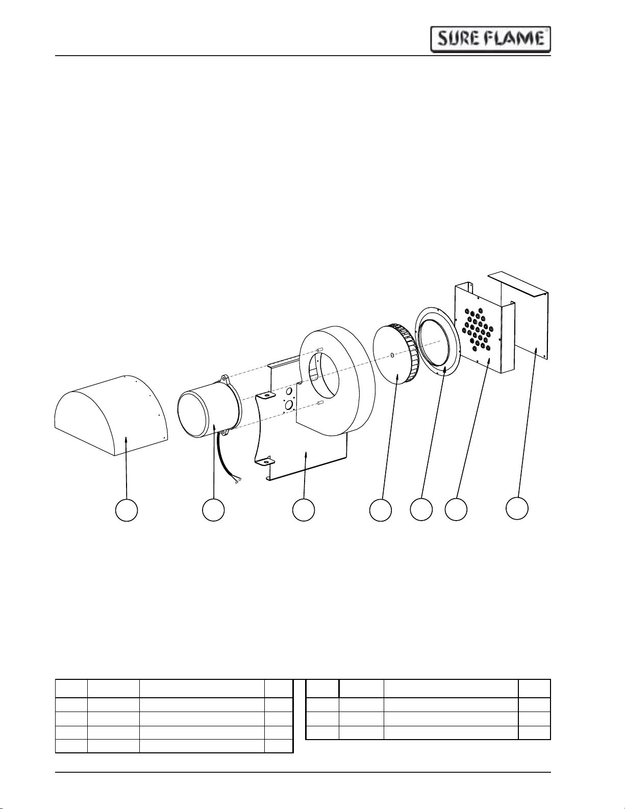
IX405 Operation & Service Manual
Burner Blower
1
Ref # Pa rt # Des cription Qty Re f # Pa rt # De s cripti on Qty
1
IX -3539 Burner Motor Cover
21276
3 IX-3534
41274 Impeller 1
18
Burner Motor
Blower Housing
2
3
1 5 1273 Inlet Cone 1
16IX-3187
17IX-3188
4
B u rner I nlet A ir Restrictor
Shroud S ide P anel
5
6
P/N 794-1 184 Rev: 1.0
7
1
1
Page 19
1
IX405 Operation & Service Manual
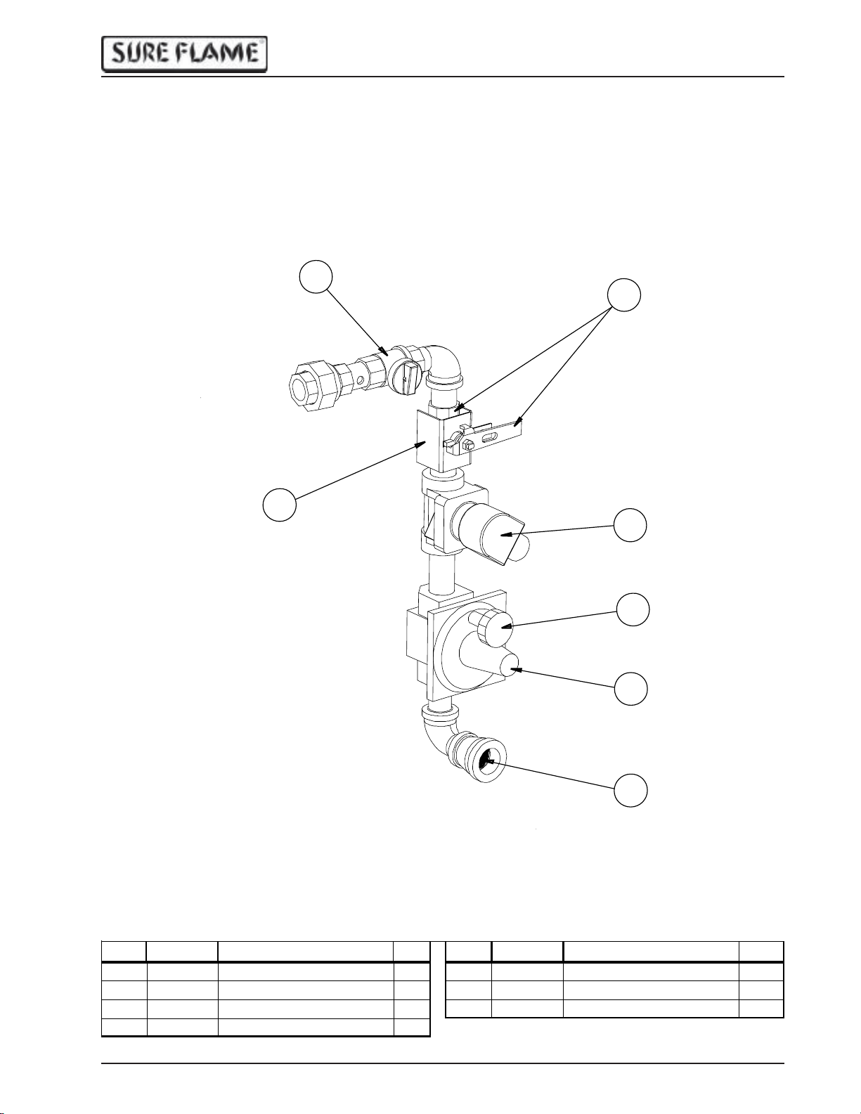
V alve Train
2
3
4
5
6
7
Ref # Part # Desc ription Qty R ef # Pa rt # Desc ription Qty
15869
2
IX -37 31 Ga s Selecto r Va lv e
3 IX-3193
44514
P/N 794-1 184 Rev: 1.0
3/4" Ma nual Valve
Locking Bracket
3 /4 " S o le no id Valve 2 4 V
159301
162524
17IX-3730
1
Vent Protector
3/4 " Regulator
Strainer
1
1
1
19
Page 20
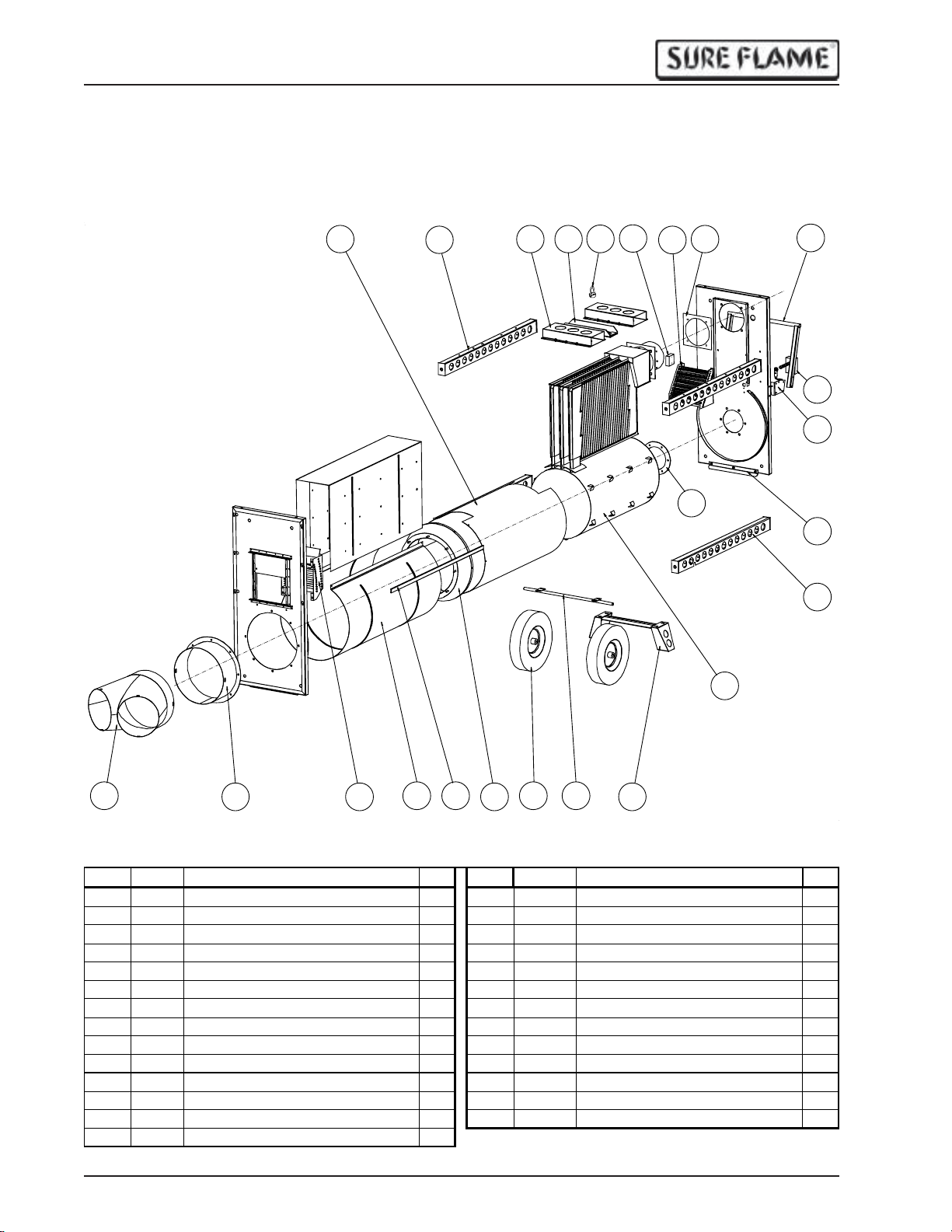
IX405 Operation & Service Manual
R
Main Body
25
24
23
22
21
20
19
11
18
17
16
15
13
12
10
1
R ef # P art # Des c ription Q ty Ref # Part # Description Qty
1 IX-5527
2 IX-5540
3 IX-5532
4 IX-5102
51261
6 IX-4524
71269
8 IX-5539
9 IX-5538
10 IX-4523
11 IX-3198
12 IX-5521
13 IX-5183
14 IX-5187
2 3
Dual Duct Adapter
16" Duct Adapter
B lower Air S traightener
Outer S hell
S Lock
Outlet C one
16" W heel
Axle
Leg Assembly
Combustion Chamber/Exchanger
B urner G as ket
Wheel S upport
Stacking Support
R H Handle Hinge (not shown)
5
1 15 IX-5187L
1 16 1278
1 17 IX-5528
1 18 IX-3201
2 19 IX-5531
1 20 IX-5535
2 21 9836
1 22 IX-5530
1 23 IX-5735
1 24 IX-5523
1 25 IX-4533
2 1199
2 1199
1
20
64
7 8
9
LH Handl e Hinge
Fan L imit Switch
Handle
E xhaust Ga ske t
A ir Deflector
Limit S witch Box
L i fting R ing
L i fting R ing B ase
Forklift Pocket
Top Support
H e a t S hie ld
O utput L imit S witc h (not s hown)
E xa ust L imit S witch (not s hown)
P/N 794-1 184 Rev: 1.0
1
1
1
1
1
1
1
1
2
2
1
1
1
Page 21
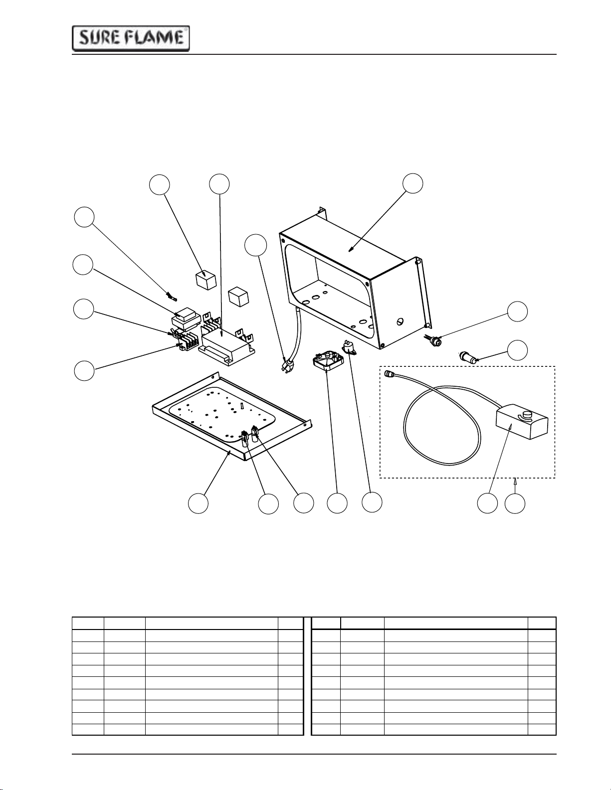
Electrical
y
IX405 Operation & Service Manual
12
13
14
15
11
10
8
9
7
6
1
R ef # P art # Des c ription Qty R ef # Part # Desc ription Qty
1 IX-5152
2 IX-5731
3 IX-5732
4 IX-5734
5 1260
6 SE-4716
7 WRS-172
8 9217
9 WRS-165
P/N 794-1 184 Rev: 1.0
Control Box Lid
S ta r t P u s h butt o n
Stop Pus hbutton
IX 410 Adjus ted Air S witch
Tipover S witch
Thermost at Jumper Plu g
Thermostat Receptacl e
Electrical Box
Power Cord
2
3
1 10 1308
1 11 9872
1 12 9884
1 13 4510
1 14 9883
1 15 9823
1 16 7723
1 17 2453
1 18 SE -4715
4
5
Ignition Con troller
R elay, 24 VAC
Fuse, 2A
Transformer
Fuse Holder
Terminal Block
Door S ea l (not s hown)
Thermostat
T hermostat Asse mbl
17
18
1
2
1
1
1
2
3.5'
1
1
21
Page 22
IX405 Operation & Service Manual
22
P/N 794-1 184 Rev: 1.0
 Loading...