

Page 1
MIC-7
Multi-Interface Controller
by SureFire Radio
© SureFire Radio, 2019
Page 2
Introduction
Internal band decoder
RS-232, CI-V, USB and Band Data interfaces
Internal RS-232 and CI-V to USB interface
Bi-directional band data port
Dual port LAN interface
Direct USB connection to Flex radios
Two units may be interconnected for SO2R operation
Automatic antenna lockout for antennas in use by
other radio
Completely configurable from front panel
Anodized aluminum case with laser engraved panels
Size: 1.4H x 6.7W x 7.6D (inches)
Weight: 1.4 pounds
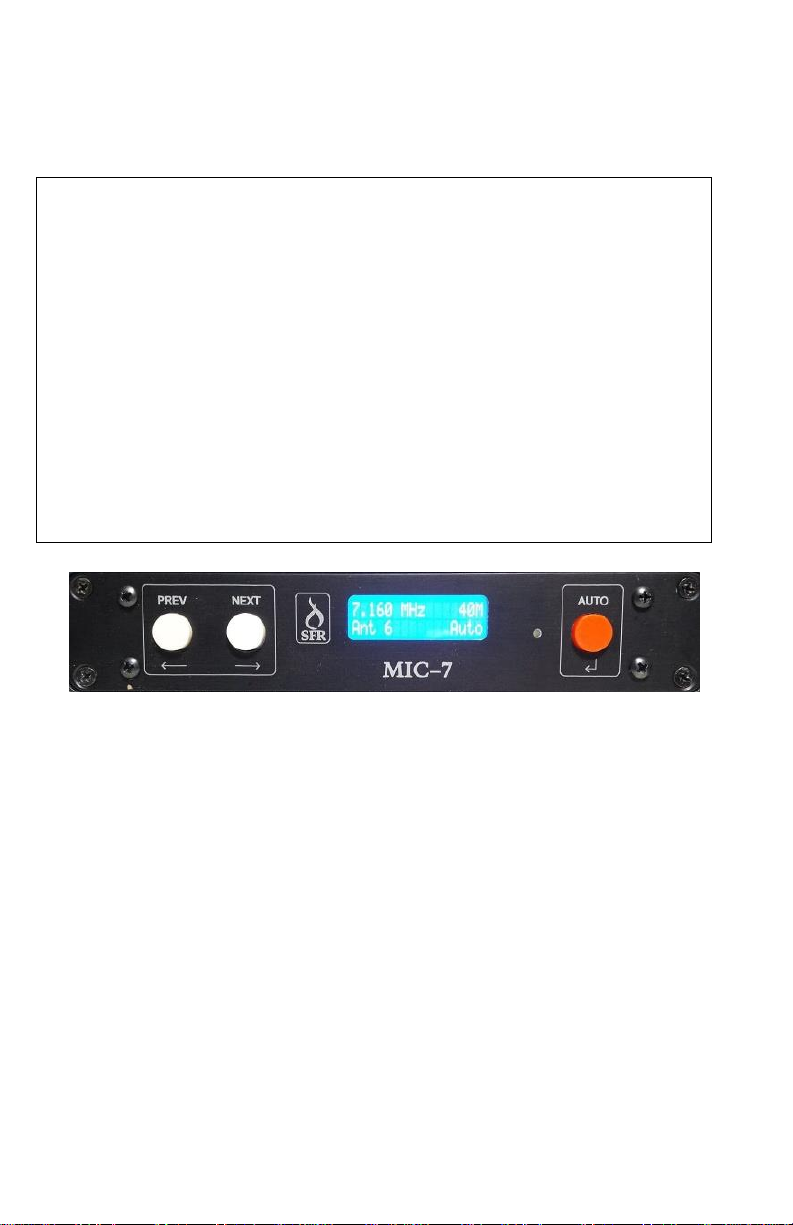
The SureFire Radio MIC-7 Multi-Interface Controller is a complete
band decoder, antenna switch controller and remote control gateway
contained in a single package. The internal band decoder supports
Icom, Kenwood, Yaesu, Elecraft and Flex radios. Most configuration is
done from the front panel (excluding the LAN interface). At the heart
of the MIC-7 is the Atmel atXMega64A3 microcontroller which
features a high performance RISC architecture while consuming very
little power and also allows the MIC-7 firmware to be upgraded in the
field by the user. There MIC-7 provides eight outputs for antenna
selection. Each output is a separate relay contact. The default
configuration provides +12VDC to select antennas. Jumper selections
allows the outputs to use any externally applied voltage. The MIC-7
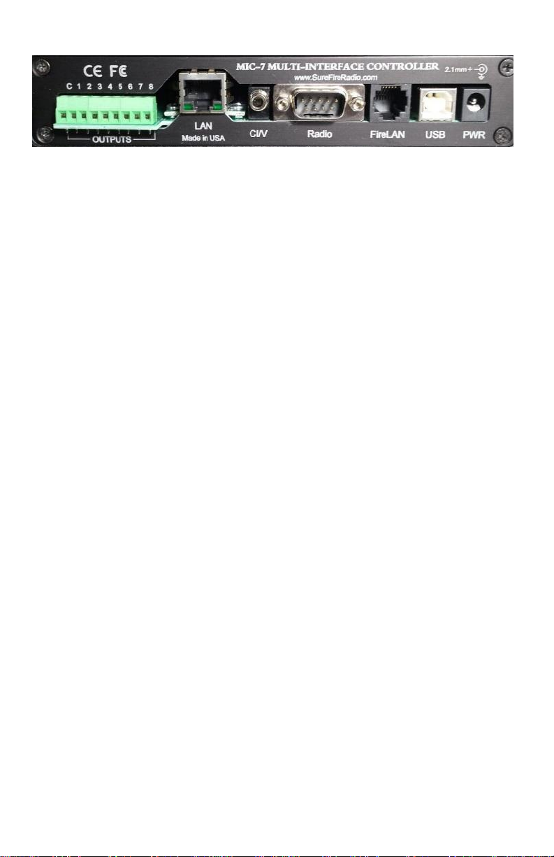
provides seven separate interface connections as described below.
Page 3
Power connection
Power may be applied to the MIC-7 with either the included power
cable or via the FireLAN connection if another device on the bus, such as
another MIC-7 or BF-100, already has a power connection. Power
requirements are 12-15vdc at 200mA plus the current required by the
relays in the antenna switch. If using the included power cable, attach
the free ends to your station power supply. The wire with the white strip
is positive. The MIC-7 is protected against reverse polarity. The power
jack is a common 2.1mm with center pin positive.
USB Port
The USB port in the MIC-7 utilizes the popular and reliable FT-232 chip
from FTDI. The USB interface is powered by the USB connection
separately from the main power to allow the COM port on your PC to
remain active even when the MIC-7 is powered off. Firmware updating is
also done using the USB port.
The MIC-7 USB port is normally connected to your PC for radio control
from your logging software. Conversion to and from RS-232 or CI-V to
USB is accomplished internally thus eliminating the need for an external
interface. The USB port may also be connected directly to Flex SDR
radios.
Band Data Port
The MIC-7 contains a bi-directional band data interface. When
operating in band data mode the band data from the radio is applied to
this port. Input levels may be between 3.3vdc and 12 vdc. Input
impedance is 100K ohms so loading on the band data lines should not
be an issue. When using the RS-232, CI-V or USB ports for radio control
the MIC-7 will automatically output band data information on this port.
Output levels are 0 and 5vdc.
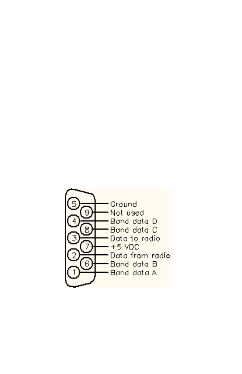
Pinout connections for Band Date are shown below in Figure 1.
Page 4
Radio RS-232 Port
The RS-232 port on the MIC-7 is the same gender as a standard PC
serial port and in most cases the same cable used to connect a radio
to a PC may be used between the radio and the MIC-7. All popular
baud rates are supported.
One unique feature of the MIC-7 is the ability to send frequency data
out the RS-232 port when using Icom radios (CI-V), Flex radio via
USB or band data. This allows simple operation of accessories such as
SteppIR controllers, automatic antenna tuners, auto tune amplifiers,
etc.. In the case of band data the frequency data being sent will
indicate the center of the band. The format of the data is in Kenwood
format and is set to 9600 baud.
Pinouts for the RS-232 connections are shown below in Figure 1.
Note that Kenwood radios may require the connection to pin 7 to
enable data transmission.
FIGURE 1
View looking into connector on MIC-7
Page 5

CI-V Port
The CI-V port is used to connect to the Remote jack on Icom radios.
This port will also output frequency data in Icom format when one of the
other interfaces are used for radio control. Input impedance is 100K
ohms so loading on the CI-V bus is negligible. The MIC-7 will
automatically acquire the proper CI-V address from the radio
data and the baud rate for the CI-V port is configurable from the front
panel.
Dual LAN Port
The MIC-7 contains a dual port LAN (Ethernet) interface. These are
network ports and not two physical ports. Connect the LAN port to your
router or switch using a standard straight-thru network cable. The IP
address and port numbers are configurable by the user. After the IP
address is initially set the rest of the LAN interface is configured using
any web browser.
Port A of the LAN interface provides remote control of the MIC-7 from
anywhere via network or internet using the MIC-7 control utility.
Port B of the LAN interface is connected directly to the radio data
stream and allows for full control of your radio from any location. If your
radio control software does not offer networking, such as setting an IP
address and port number, there is a virtual COM port utility available
which allows setting the IP address and port number and assigning them
to a standard COM port.
FireLAN Port
The FireLAN port is used to connect to other SureFire Radio devices.
Connecting the MIC-7 via FireLAN to the BF-100 BandPass Filter unit
provides automatic filter selection for the current band on the radio. The
FireLAN bus may also be connected to another MIC-7 for SO2R
operation to provide automatic antenna lockout when an antenna is in
use by the other radio. This port also provides power in addition to data
so only a single connection to a power source is required, eliminating the
need for multiple power cables and making for a cleaner installation. A
30" cable is supplied to connect to other devices.
Page 6

Relay Outputs
The MIC-7 has eight relay outputs for selecting antennas. The default
settings provide +12 vdc on each active output with the "C" connection
being ground. These outputs are made to the screw terminals at the
rear of the unit.
Configuring the MIC-7
All configuration except for the LAN is done from the front panel.
Enter Configuration Mode by simultaneously pressing NEXT and PREV.
After entering Configuration mode use NEXT and PREV to step through
the menu options. The descriptions of the menu options are below.
Radio Configuration
Access the Setup Radio menu by entering Configuration Mode and
then pressing NEXT once and then press AUTO at the Setup Radio
screen.
The first option is the Radio Number. Select the desired radio number
by pressing NEXT or PREV and then pressing AUTO to accept the
current setting.
Next selection is the Radio Type. Use NEXT and PREV to select the
desired radio type and then press AUTO.
Now use NEXT and PREV to select the proper baud rate for the radio.
The USB port will be also be set to this baud rate. Press AUTO to
accept the displayed baud rate.
The next option is Radio Polling. When disabled the MIC-7 will not ask
the radio for data and your logging or control software must
periodically ask the radio for data. Normal operation is to have polling
enable. Only disable polling if you are getting erroneous data when
using the MIC-7 with radio control software. Enable or disable polling
using NEXT and PREV and then press AUTO.
If you are using an Icom radio the MIC-7 will now ask you to turn the
VFO knob to acquire the CI-V address. Note that you much have CI-V
Transceive enabled on the radio.
Page 7

You are now finished setting up the radio interface.
Auto Band Change
This option allows the MIC-7 to return to automatic antenna selection
mode when changing bands. For most users the option should be
enabled. If you wish to change this option, press AUTO at the Auto
Band Change screen and use NEXT and PREV to enable or disable this
option. Press AUTO to accept your choice.
Control via USB
Normally the MIC-7 USB port is used for radio control and the LAN
port is used to control the MIC-7. If you wish to control the MIC-7 via
USB set this option to Enabled. When enabled there will not be and
radio data present on the USB port. Disable this option to allow radio
control via the USB port.
Restore Defaults
This option will restore the MIC-7 to factory default settings. To reset
the MIC-7 to factory defaults press AUTO at the Restore Defaults
screen. Use NEXT to select YES to restore default settings or NO to
cancel. Press AUTO after you have made your selection.
Reset IP Address
This option is used to reset the IP address of the LAN interface to
0.0.0.0. Use this option if you accidentally set the IP address to one
outside of your local network and are unable to connect to it. Press
AUTO at the Reset IP Address screen and then use NEXT or PREV to
select YES to reset the IP address or NO to cancel. Press AUTO when
done It will take several seconds to reset the address.
Default Antenna Selection
The last thing to compete the setup of the MIC-7 is to set the default
antenna for each band. This is a simple process and is done at the
main operating screen. First place the radio on the desired band and
then use NEXT and PREV to select the desired antenna. After the
Page 8

antenna is selected press AUTO for longer than 3 seconds. Do this for
each band to complete the configuration.
LAN Configuration
Configuring the MIC-7 LAN interface is a two step process. The first
step is to connect the MIC-7 to your local network and then run the
IPSetup utility. The MIC-7 should be shown in the utility as SBL2E. If it
isn't showing click on the Search Again button. After it appears in the
list you now enter the desired IP address. Be sure the address you
enter is compatible with your local network. Next set the Network
Mask. For almost all users this should be set to 255.255.255.0. Lastly
set the Baudrate to 9600. No entries are required for Gateway and
DNS. Now click the Set button. After a few seconds click on the Search
Again button and the MIC-7 should show up showing the new IP
address. Now click on the Launch Webpage button. When the web
page comes up you can set the two port numbers for the LAN
interface. These are in the second section of the page under Incoming
TCP settings. The defaults are 23 and 24 but it is highly recommended
you change these to numbers between 5000 and 60000. No other
settings on the page should be changed. Click on the Submit New
Settings button at the bottom of the page. Next click on the Serial link
at the top of the page. Be sure the baud rate for both ports is set to
9600. No other changes should be made on the Serial page. Click on
Submit New Settings to save the baud rate. The LAN configuration is
now complete.
Operating the MIC-7
The MIC-7 is a very simple device to operate. For most users it will be
a set and forget device. If you wish to use an antenna other than the
default one use NEXT and PREV to select the desired antenna. Press
AUTO to return to the default antenna. The default antenna will
automatically be selected when changing bands if the Auto Band Change
option is enabled.
 Loading...