

Page 1

Proudly Made in
the USA
INSTALLATION & OPERATIONS
PROUDLY MADE IN THE USA
MANUAL
Page 2

INTRODUCTION
The BMS-100 system is designed to operate in Combustor and Flare applications in the Oil and Gas Industry.
The BMS-100 system utilizes the SureFire FTL series, FT-1-S, FT-1-ST, and FTL-FFG units to provide ignition.
The controller’s display is designed to operate in ambient temperatures from – 40⁰F to 131⁰F, and is coated for
corrosion resistance. The unit is mounted in a NEMA 4X enclosure supplied with a UV resistant keypad. Each
unit includes function indicator LED’s, and contains a status code chart that is printed on the overlay to provide assistance in troubleshooting. The unit requires 12 VDC or 24 VDC power, and is solar ready with a specific solar power termination port.
This apparatus is suitable for use in Class1, Division 2, Groups C and D, or unclassified locations.
The BMS-100 detects a flame utilizing the igniter or thermocouple as the flame sensing device. Once the ignition flame makes contact with the igniter or thermocouple, a signal is sent to the BMS-100 and the unit registers a flame. The BMS-100 also provides 2nd stage solenoid and actuator valve timing control after flame is
proven.
The BMS-100 also comes with an adder daughter board that allows 4-20mA input and high temperature safety
shutdown. Plus a USB data logging port to log pilot flame with real time and date stamp.
The BMS-100 contains relighting capability, providing the combustors and flare application with more opportunity to re-ignite the fuel gas.
Every SureFire system will pass complete factory QA/QC testing.
Also available is a control solenoid valve, Actuator valve, Standby Pressure Switches and FT ignition unit.
We are dedicated to providing quality American made safety control systems for Combustor and Flare Applications. The system has been developed through thousands of hours of critical design, engineering, and field
testing.
2
Page 3

TABLE OF CONTENT
Certifications and Warnings 4
Warranty Statement 5
BMS-100 Description
Enclosure 6
Circuit Board 7
Graphic Overlay 8
LED Indicators / Keypad Functions 9
Component Description
SureFire Ignition Units 10
Additional Components 11
Installation Guide 12-15
Installation Wiring Diagram 16
Fuel Train Diagram 17-19
Operation Guide 20-21
Operation Guide: Sequence of Operation / Flow Chart 22-27
Specifications 28
Troubleshooting Guide 29-32
Daughter Board Information and Installation______________________________________________33-35
Daughter Board Setup________________________________________________________________36-37
Installation Notes 38
BMS - 100 Software Versions 39
Contact and Version Info 40
3
Page 4

Certified to:
UL 61010 - 1
CERTIFACTIONS AND WARNINGS
UL 61010 –2 030
Rated Input Voltage: 12VDC
ISA 12.12.01
Wattage: 60.0 MAX/ 7.2 AVG
Amperage: 5.0 amps MAX/0.6 amps AVG
Class 1, Division 2, Groups C and D, or Unclassified Applications, T4
Ambient Temperature Range: -40°F ≤Tamb ≤131°F (-40°C ≤Tamb ≤55°C)
WARNING
EXPLOSION HAZARD - SUBSTITUTION OF COMPONENTS MAY IMPAIR
SUITABILITY FOR CLASS I, DIVISION 2, GROUPS C AND D, OR UNCLASSIFED APPLICATIONS;
WARNING
EXPLOSION HAZARD - DO NOT DISCONNECT EQUIPMENT UNLESS POWER HAS BEEN
SWITCHED OFF OR THE AREA IS KNOWN TO BE NON-HAZARDOUS;
WARNING
EXPOSURE TO SOME CHEMICALS MAY DEGRADE THE SEALING
PROPERTIES OF MATERIALS USED IN THE FOLLOWING DEVICES: HAMLIN ELECTRONICS
RELAY, MODEL HE721A0500, ALLIED ELECRONICS RELAY, MODEL JW2SN-DC12V, AND
PANASONIC RELAY, MODEL DS2E-SL2-DC5V
WARNING
SUBSTITUTION OF THE FOLLOWING COMPONENTS MAY IMPAIR SUITABILITY FOR
DIVISION 2
Reference Designation Description Type of Protection
K1, K2, or K3 Relay Sealed Contacts
4
Page 5

WARRANTY
Warranty Statement
SureFire warrants all equipment of its own manufacture to be free of defects in material and
workmanship for a period of twenty-four (24) months from the date of manufacture.
SureFire’s sole obligation hereunder shall be expressly limited to repair or exchange free of
charge, F.O.B. Aztec, NM, USA of such defective equipment. SureFire’s obligation under
this warranty is limited to the above and does not apply to claims which are a result of
improper installation, misuse, maladjustment, abnormal operating conditions, or lack of
routine maintenance as determined by SureFire. Nor does the warranty include the
furnishing of service for maintenance or problems arising from the foregoing causes. No
claims for labor, installation, removal, transportation, or other expenses will be recognized.
Notwithstanding any stipulation of the purchaser to the contrary, all other obligations,
representations, warranties and conditions, express or implied, statutory or otherwise,
including any implied warranties or conditions of merchantability, quality or fitness are
hereby excluded and, SureFire shall not be liable for any loss, cost or damages, of any kind
whatsoever, whether consequential, indirect, special or otherwise, arising out of or in
connection with the equipment or any defect therein, even if caused by the negligence of
SureFire, its employees or agents. The provisions hereof relating to the warranty and
limitations hereon and limitation of liability shall continue to be enforceable between the
parties notwithstanding termination of the within agreement for any reason including
fundamental breach. Equipment not of SureFire manufacture shall pass through to the end
user the vendor’s or manufacturer’s standard warranty.
5
Page 6
BMS-100 DESCRIPTION
Enclosure
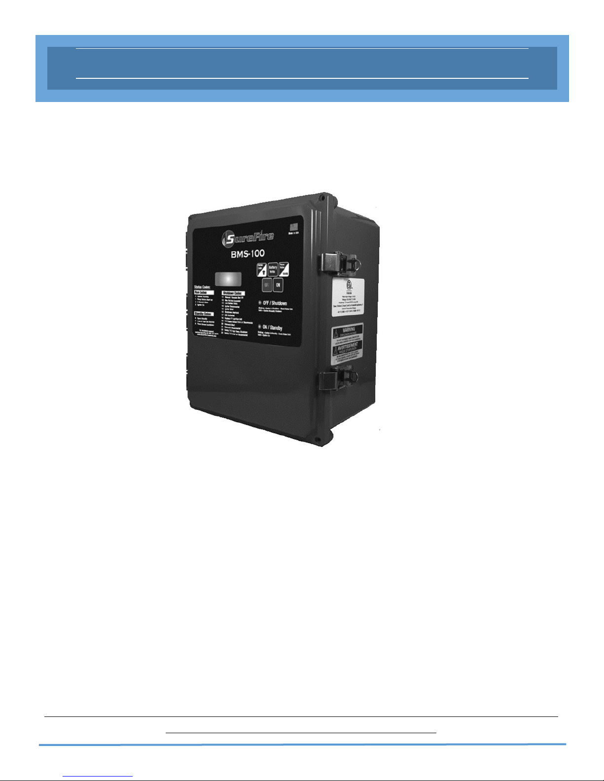
The SureFire BMS-100 system uses a polycarbonate NEMA 4X Enclosure to house the circuit board. The
Graphic overlay, with a membrane keypad, is mounted on the exterior of the enclosure.
The NEMA 4X enclosure provides a high level of protection from harsh outdoor elements:
Windblown Dust Protection
Water Damage Protection - Rain, Sleet, Snow, Splashing and Direct Water Contact
Corrosion Protection
External Formation of Ice Protection
The Enclosure is IP66 certified, meaning it has been tested to the following:
Dust tight, no ingress of dust; complete protection against contact
Water projected in powerful water jets (12.5mm nozzle) against the enclosure from any direction
shall have no harmful effects.
When drilling holes in the enclosure, ensure IP66 fittings are used to maintain the IP66 standard. Failure to
use IP66 standard fittings nullifies the IP66 certification.
WARNING:
6
Page 7

BMS-100 DESCRIPTION
BMS-100 Circuit Board
The SureFire BMS-100 system is controlled by state of the art, non-arcing electronics that monitor and control all combustor and flare applications. It comes with 2 LED indicators and a status code LED display.
7
Page 8

BMS-100 DESCRIPTION
Graphic Overlay
The overlay provides the list of status codes on the face. The overlay is used for interfacing with the system
and acquiring troubleshooting information.
8
Page 9
BMS-100 DESCRIPTION
LED Indicators
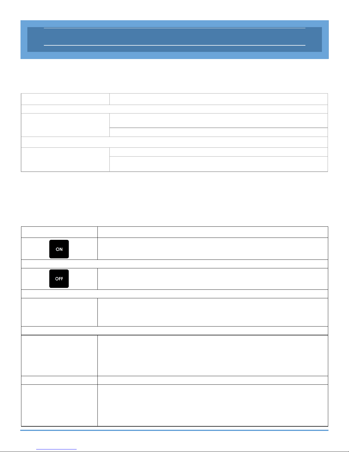
The circuit board LEDs illuminate through the lid of the enclosure. The LEDs indicate the following:
LED Indicator Status
GREEN
RED
LED ON - Indicates that the system is on and operating properly
Blinking - Indicates a standby interlock is activated
LED ON - Indicates that the system is off
Blinking - Indicates a shutdown failure or interlock has been activated
5 Button Keypad:
The SureFire BMS-100 has a 5 button keypad to assist in controlling and monitoring the system.
Note: Secondary functions can only be adjusted, when system is unlocked. Pre-purge time and timing
between ignition attempts is now the same.
Button
Turns the unit ON.
Turns the unit OFF.
Functions
Primary: Displays the code that corresponds with the current unit status.
Secondary: Press button for 5 seconds to unlock the system.
Tertiary: Up arrow - Increments settable value for pre-purge & safety T/C limit.
Primary: Displays the current battery voltage.
Secondary: Press button for 5 seconds to display current pre-purge timing.
To set pre-purge timing: Unlock system, press & hold Battery Volts button & use
the up arrow button to set timing. Range: 01 - 10 minutes pre-purge time.
Primary: Displays the current flame strength value for the igniter or T/C.
Secondary: Press for 5 seconds to display current safety T/C limit.
To set safety T/C limit: Unlock system, press & hold T/C HTS button & use the
up arrow button to set limit. Range: 100°F - 2400°F.
9
Page 10

COMPONENT DESCRIPTION
SureFire FTL-U and FT-Series Ignition Unit.
The SureFire BMS-100 is compatible with any of the Flare Pilots ignition
units designed for combustor and flare applications and certain FT-Series
ignition units designed for firetube applications.
FTL-U Flare Pilot
The FTL-U are stainless steel, straight style pilots for open flare applications. It utilizes the igniter element to sense the pilot flame.
FTL-U flare pilot is custom to each application, max length on 1”
nipple is 6’-0”.
Pilot nozzle and igniter assembly are easily field replaceable.
FTL-F Flare Pilot
The FTL-F are stainless steel, straight pilots for open flare application.
It utilizes a thermocouple to sense the pilot flame.
FTL-F flare pilot are reliable ignition system for flare applications.
Thermocouple and igniter element are easily field replaceable.
FT-1 Series Ignition Unit
The FT-1 series ignition unit is a aluminum block with a stainless steel
nozzle for firetube application. It utilizes the igniter or thermocouple to
sense the pilot flame.
Optional Flame Sensors
Igniter
Utilizes ohms resistance reading to verify flame
Armored wiring harness to: 500°F duty / 800°F flash
Direct termination to BMS-100 controller
Thermocouple
Utilizes temperature reading to verify flame
The unit above is utilizing the Igniter Element
FTL-F
FT-1-S (above)
as a flame sensing mechanism.
FTL-U
Armored wiring harness rated to:
1000°F duty / 1500°F flash
Direct termination to the BMS-100 controller
FT-1-ST (above)
The unit above is utilizing a Thermocouple as
a flame sensing mechanism.
10
Page 11
COMPONENT DESCRIPTION
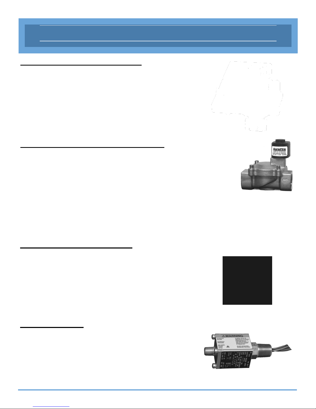
12 Volt, 1in. SureFire Actuator
Part #: 51901065
Controls the main fuel gas to the main burner.
Factory programmed and pre-wired so no adjustment is necessary.
3 wire termination.
Applications include - Combustor and Flare systems.
1in. & 2 in. SureFire Solenoid Valve
1” Part #: 51900605
2” Part #: 51900605-2
Fail closed device.
No adjustment necessary.
Simple termination and installation.
Applications include - Combustors and Flare
systems.
1/4 in. ASCO Solenoid Valve
Part #: 51900601
Fail closed device.
No adjustment necessary.
Simple termination and installation
Application include - Combustor and Flare systems.
Pressure Switch
Part #: 51901001
Used on a variety of standbys and shutdowns.
Can be used as normally open or normally closed.
Adjustable from 2psi — 12psi.
11
Page 12
INSTALLATION GUIDE
Enclosure Installation
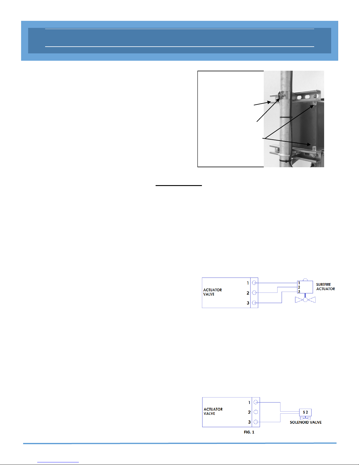
1. The enclosure is to be mounted on a pole or a building
that is capable of supporting 10 lbs.
2. Position the enclosure so that the LED display is clearly
visible for the operator.
Unistrut
Unistrut Clamp
3. Install conduit seal-off fittings for ALL electrical
connections at the enclosure.
4. Installation must comply with the local electric code.
Mounng Hardware
WARNING
Before any welding is attempted, disconnect all wires going to the circuit board. Any damage caused
by welding to the SureFire BMS is NOT covered under warranty.
Before terminating any wires, be sure no power is supplied to the controller.
Any damage caused by standing on or using the enclosure as a step is NOT covered under warranty.
2nd Stage Valve Control
SureFire Actuator / Solenoid Valve
1. Install the SureFire Actuator or Solenoid Valve in the
fuel train for the vent or main line.
2. When an Actuator is being utilized. Terminate wires on
terminal block labeled Actuator Valve (1, 2, and 3) from
the SureFire Actuator Valve terminals (1, 2 and 3), See
note below.
NOTE: SureFire Actuator 1 @ Terminal block 1
SureFire Actuator 2 @ Terminal block 2
SureFire Actuator 3 @ Terminal block 3
NOTE: Must use SureFire Actuator valve or an actuator
approved by SureFire.
3. When a solenoid is being utilized. Terminate solenoid
wires on ports 1 & 3 on Actuator Valve terminal block.
Port 2 is not used. See Fig. 1.
12
Page 13
INSTALLATION GUIDE
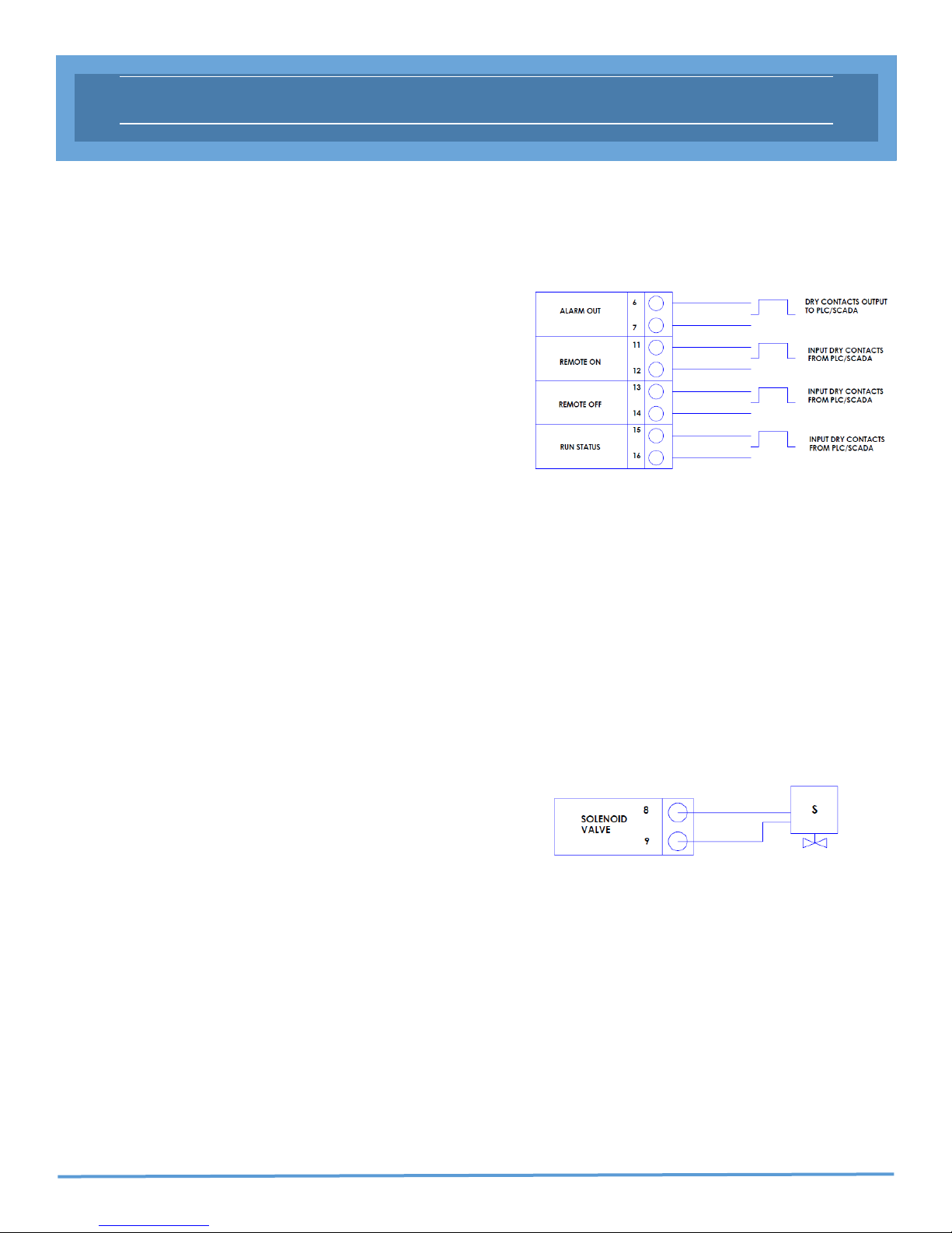
PLC/Scada Connection
The proper connection method for the Alarm Out, Remote On,
Remote Off and Run Status is as follow:
1. Terminate wires from the RTU/PLC to the Alarm out
terminal (Ports 6-7)
2. Terminate wires from the RTU/PLC to the Remote ON
terminals (Ports 11-12) and Remote OFF terminals (Ports
13-14)
NOTE: The remote ON / OFF receives a signal from a
momentary switch (closed or open loop) from the
PLC/SCADA to turn unit ON / OFF remotely.
NOTE: During a Shutdown error, unit cannot be reset remotely.
3. Terminate wires from the RTU/PLC to the Run Status
terminals (Ports 15-16)
NOTE: These terminations are left un-touched if not used.
NOTE: The above ports are dry contacts and no voltage or
current should be applied to them.
1st Stage Valve Control
Solenoid Valve
1. Ensure main supply gas is shut off.
2. Locate the pilot gas supply line.
3. Install a 1/4” ASCO or 1” SureFire solenoid valve in the
appropriate location in the pilot fuel train.
4. Cut and bend custom 3/8” tubing and connect to tubing
fittings on solenoid.
5. Use proper connectors and conduit for wiring.
6. Terminate solenoid wires at the Solenoid Valve
terminals (port 8-9)
NOTE: See pages 17, 18 and 19 for solenoid location on fuel
trains for combustors and flares.
NOTE: Solenoid proper flow direction.
Reference ASCO: 2 = Inlet and 1 = Outlet
13
Page 14
INSTALLATION GUIDE
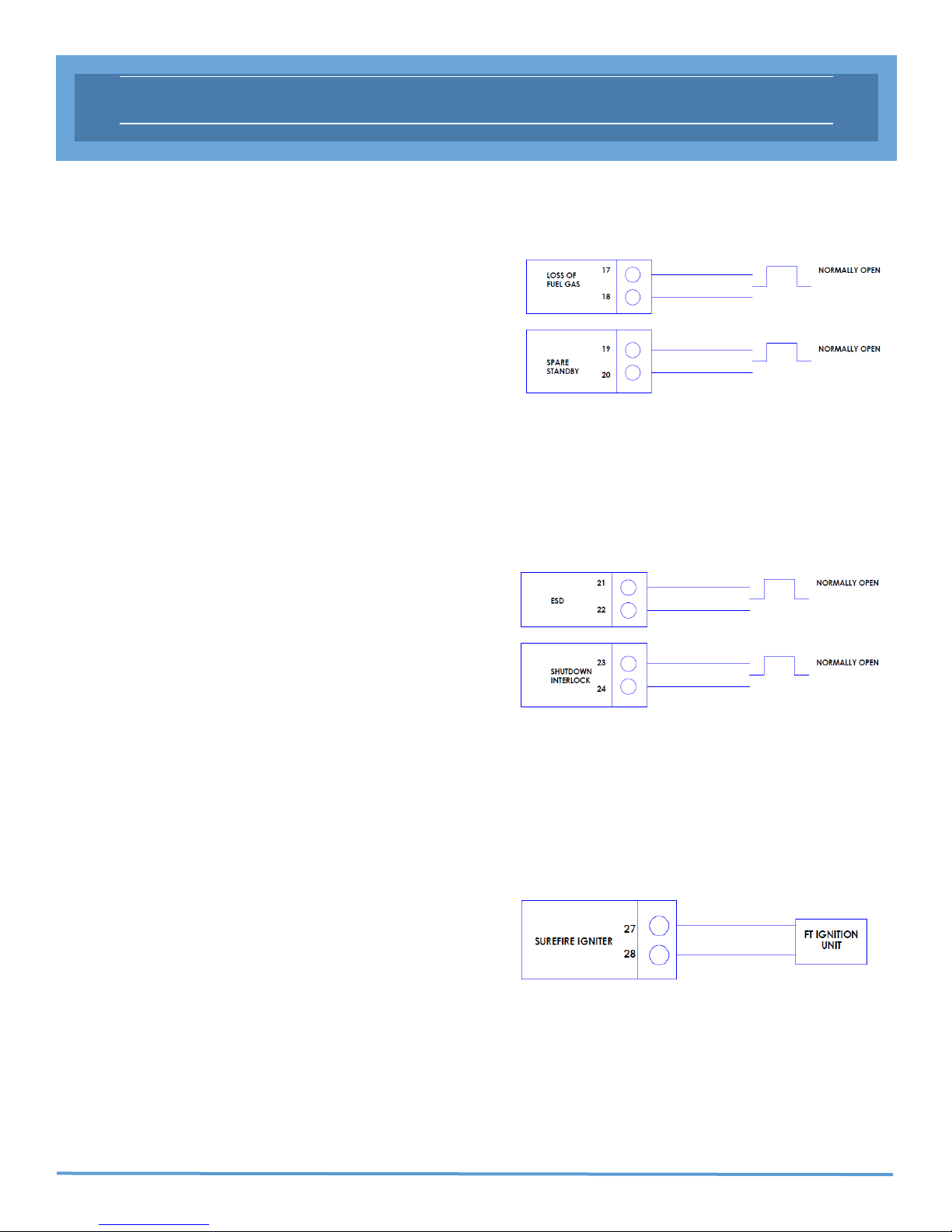
Standby
1. Install a normally open or normally close dry contact
device in one of the assigned terminals (Ports 17-18 &
19-20)
2. If no device is used, a jumper needs to be in place at the
assigned terminal.
NOTE: Closed Contact = Normal Operation
Open Contact = Failed Operation
NOTE: Standby does not require a local reset to re-start
system.
Shutdown
1. Install a normally open or normally close dry contact
device in one of the assigned terminals (Ports 21-22 &
23-24)
2. If no device is used, a jumper needs to be in place at
the assigned terminal.
NOTE: Closed Contact = Normal Operation
Open Contact = Failed Operation
NOTE: Shutdown requires a local reset to re-start system.
SureFire FTL or FT-1 Series Ignition Unit
1. Ensure all supply gas is turned off and locked out /
tagged out
2. Install the FT unit in the flare or combustor.
3. The igniter has two white wires that are not polarity
sensitive and terminate wires to terminals (ports 27 & 28).
4. Flame Sensor wires need to be terminated as described on page 15.
14
Page 15

INSTALLATION GUIDE
Flame Sensing Switch (Igniter or
Thermocouple)
Flame sensing mechanism will be dependent on the ignition
unit being utilized. Ensure proper flame sensing mode has been
selected. See Fig.1
For Igniter flame sensing, the igniter wires terminate at
ports 27 & 28 and position switch on igniter.
For thermocouple flame sensing terminate the red (-) wire
at port 5 and the yellow (+) wire at port 4 and position
switch on thermocouple.
NOTE: Switch must be placed in proper position before power
is applied to circuit board. Do not switch while circuit
board is powered up.
Fig. 1
Solar Panel / 12 or 24 VDC Power Source
1. Install 12 VDC Solar Panel or a 12V / 24V DC power source
2. Connect negative (-) terminal to port 29
3. Connect positive (+) terminal to port 30
NOTES:
Maximum rating for solar panel is 75 watts
When using 24 VDC, amps are limited, max current is 75 watts
or 3 amps (Current limiting device is recommended)
Circuit board has internal charge controller to charge 12 VDC
battery, if a battery is connected to port 31 & 32
When using a 12VDC power source, output voltage needs to be
set at
14VDC.
Battery
1. Install a 12VDC SLA battery within an enclosure
separate of the SureFire enclosure.
2. Connect negative (-) terminal to port 31
3. Connect positive (+) terminal to port 32
NOTES:
If battery is more than 10 feet away from SureFire
controller, use larger wire as needed. See page 28.
If utilizing 12 VDC power supply, set voltage @ 13.4
VDC. Power supply should be rated for 90 + watts.
15
Page 16

INSTALLATION WIRING DIAGRAM
16
Page 17
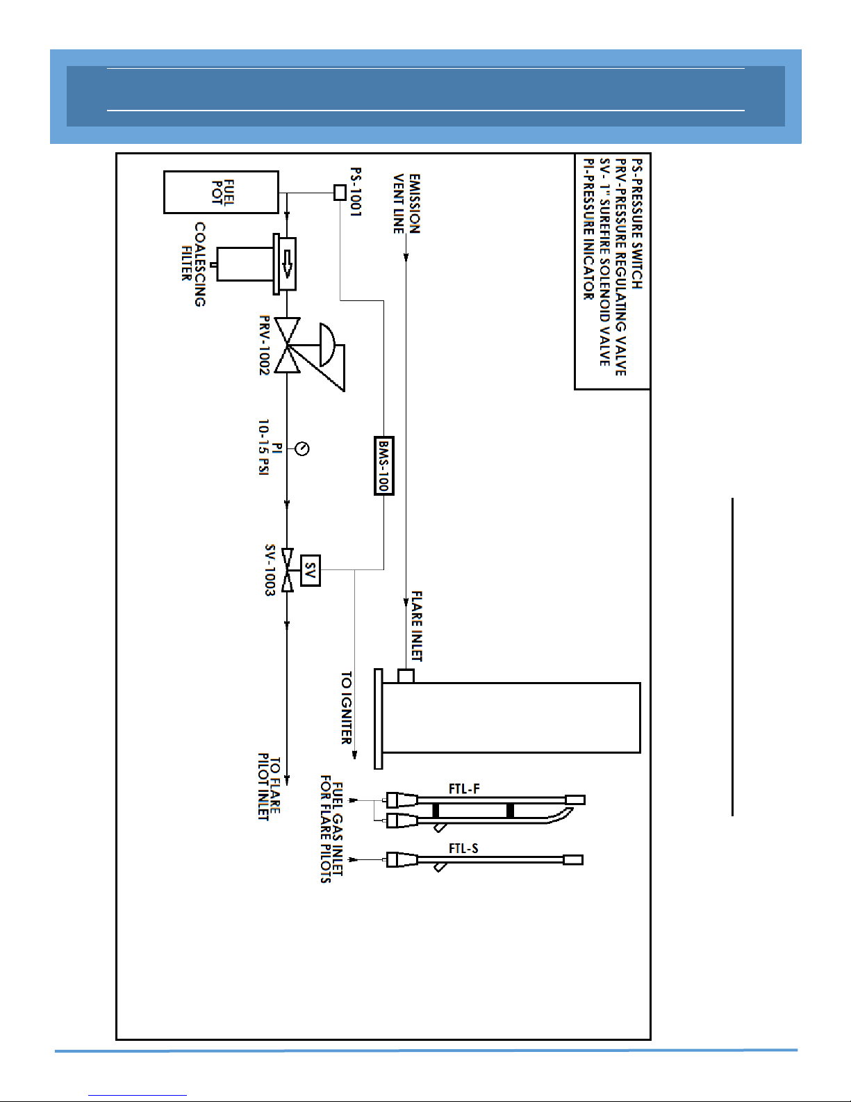
1” SOLENOID FUEL TRAIN
1” SureFire Solenoid Fuel Train
17
Page 18

1” SOLENOID / ACTUATOR FUEL TRAIN
1” SureFire Solenoid / Actuator Fuel Train
18
Page 19
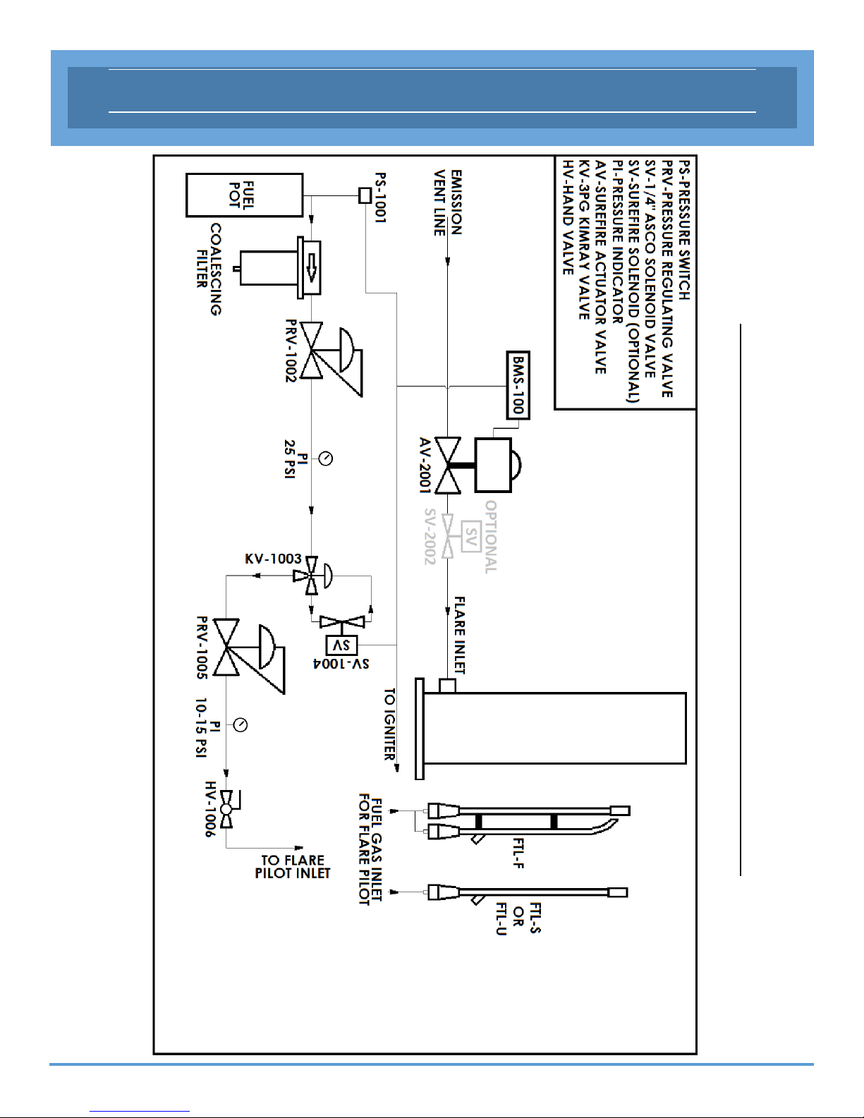
1/4” SOLENOID / 3PG / ACTUATOR FUEL TRAIN
1/4” ASCO Solenoid / 3PG Valve / Actuator Fuel Train
19
Page 20
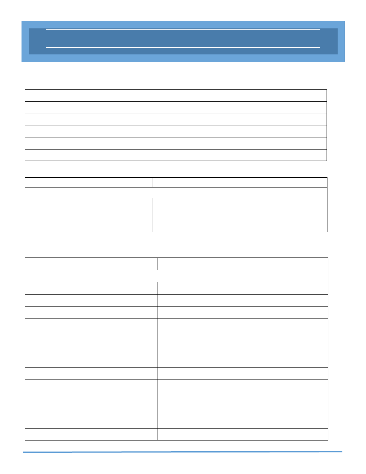
Status Code
Run Codes Description
OPERATIONS GUIDE
00
01
04
05
Standby Codes Description
06
07
08
Shutdown Codes Description
11
System Running
Purge Before Start-up
5 Second Alarm
Igniter On
Spare Standby
Loss of Fuel Gas Standby
Flame Sense Countdown
Manual / Remote Shut Off
12
13
14
15
16
17
18
19
20
21
22
23
Max Retries Exceeded
Low Battery Voltage
Igniter Disconnected
Igniter Short
Shutdown Interlock
ESD Activated
Replace FT-Ignition Unit
T/C Flame Sensor Error or Disconnected
Solenoid Short
Solenoid Disconnected
Safety T/C High Temp. Shutdown
Safety T/C Error or Disconnected
20
Page 21

OPERATIONS GUIDE
Run Status
The Run Status (Ports 15-16) is a open/closed contact switch. The Run Status can be terminated at the RTU/
PLC device and provide remote monitoring of the unit.
Unit Status Run Status GREEN-LED RED-LED
Manual OFF Open OFF ON
Shutdown Open OFF Blinking
Standby Open Blinking OFF
Unit ON
Closed ON OFF
(Status Code 00)
Alarm Out
The Alarm Out (Ports 6-7) is an open/close contact switch. The Alarm Out can be terminated at the RTU/PLC
device and provide remote monitoring of the unit.
Note: Table content below is when system is running.
Unit Status Alarm Out GREEN-LED RED-LED
Manual OFF Open OFF ON
Shutdown Open OFF Blinking
Standby Closed OFF OFF
Unit ON
(Status code 00)
Closed ON OFF
21
Page 22

OPERATIONS GUIDE - SEQUENCE OF OPERATION
Ignion Process with out Daughter Board
1) Press the ON Button
2) Pre-purge - Pre-purge countdown displayed. Green LED ON.
3) Audible Alarm - 5 second countdown displayed. Green LED ON.
4) Igniter - 8 second countdown displayed. Green LED ON
5) Solenoid valve opens - Igniter remains on for another 5 seconds. Green LED ON.
6) Ignition is achieved and a 30 second flame proof timing begins. Pilot ignites. Green LED ON.
7) Flame is sensed, flame proof timing countdown expires, the display reads “On” (Status code 00). Green
LED ON.
8) 30 second timer begins before actuator valve opens (count down not visible).
9) After 30 seconds the actuator valve opens.
Re-Ignion Process - Flame Out
1) Once the system recognizes that no flame is sensed, the system will automatically begin the re-ignition
process.
2. Reference step 2 - 7 in the “Ignition Process Section”
Re-Ignion Process - Standby
1) System in standby. Blinking Green LED.
2) Once the System resolves the Standby issue, the system will automatically begin the re-ignition process
3) Reference step 2- 7 in the “Ignition Process Section”
Re-Ignion Process - Shutdown
1) The System requires manual reset in the event of a shutdown
2) System in shutdown. Blinking Red LED.
3) Once the Shutdown issue has ben resolved, press the OFF button then ON button to reset.
4) Reference step 2 - 7 in the “Ignition Process Section”
22
Page 23

OPERATIONS GUIDE - FLOW CHART
Flowchart without Daughter Board
23
Page 24

OPERATIONS GUIDE - SEQUENCE OF OPERATION
Ignion Process with Safety T/C (Daughter board installed)
1) Press the ON Button
2) Pre-purge - Pre-purge countdown displayed. Green LED ON.
3) Audible Alarm - 5 second countdown displayed. Green LED ON.
4) Igniter - 8 second countdown displayed. Green LED ON
5) Solenoid valve opens - Igniter remains on for another 5 seconds. Green LED ON.
6) Ignition is achieved and a 30 second flame proof timing begins. Pilot ignites. Green LED ON.
7) Flame is sensed, flame proof timing countdown expires the display reads “T/C temperature value” (Status code 00). Green LED ON.
8) Thermocouple temperature is observed.
Re-Ignion Process - Flame Out
1) Once the system recognizes that no flame is sensed, the system will automatically begin the re-ignition
process.
2. Reference step 2 - 7 in the “Ignition Process Section”
Re-Ignion Process - Standby
1) System in standby. Blinking Green LED.
2) Once the System resolves the Standby issue, the system will automatically begin the re-ignition process
3) Reference step 2- 7 in the “Ignition Process Section”
Re-Ignion Process - Shutdown
1) The System requires manual reset in the event of a shutdown
2) System in shutdown. Blinking Red LED.
3) Once the Shutdown issue has ben resolved, press the OFF button then ON button to reset.
4) Reference step 2 - 7 in the “Ignition Process Section”
24
Page 25

OPERATIONS GUIDE - FLOW CHART
Flowchart with Safety T/C (Daughter Board installed)
25
Page 26

OPERATIONS GUIDE - SEQUENCE OF OPERATION
Ignion Process with Daughter Board, Safety T/C, and 4-20mA Input
1) Press the ON Button
2) Pre-purge - Pre-purge countdown displayed. Green LED ON.
3) Audible Alarm - 5 second countdown displayed. Green LED ON.
4) Igniter - 8 second countdown displayed. Green LED ON
5) Solenoid valve opens - Igniter remains on for another 5 seconds. Green LED ON.
6) Ignition is achieved and a 30 second flame proof timing begins. Pilot ignites. Green LED ON.
7) Flame is sensed, flame proof timing countdown expires, the display reads “T/C temperature” (Status
code 00). Green LED ON.
8) Thermocouple temperature is observed. Green LED ON.
9) 4-20mA pressure input is monitored. Green LED ON.
10) Actuator valve opens and closes according to 4-20mA pressure input. Green LED ON.
Re-Ignion Process - Flame Out
1) Once the system recognizes that no flame is sensed, the system will automatically begin the re-ignition
process.
2. Reference step 2 - 7 in the “Ignition Process Section”
Re-Ignion Process - Standby
1) System in standby. Blinking Green LED.
2) Once the System resolves the Standby issue, the system will automatically begin the re-ignition process
3) Reference step 2- 7 in the “Ignition Process Section”
Re-Ignion Process - Shutdown
1) The System requires manual reset in the event of a shutdown
2) System in shutdown. Blinking Red LED.
3) Once the Shutdown issue has ben resolved, press the OFF button then ON button to reset.
4) Reference step 2 - 7 in the “Ignition Process Section”
26
Page 27

OPERATIONS GUIDE - FLOW CHART
Flowchart with Daughter Board, Safety T/C, and 4-20mA Input
27
Page 28

SPECIFICATIONS
Power Supply Specifications
Device Specification
Battery 12VDC —13.4VDC
12 VDC Power Supply SET @ 13.4 VDC
Solar Panel / 24 Volt Input 12 VDC Solar Panel / 24 Volt DC Power Supply
Note: Current limitations: 7 amps @ 12 VDC and 3 amps @ 24 VDC
Solar Panel 75 WATT Maximum (Solar panel not tested by Intertek)
Ignition Unit Specifications
Device Specification
Ignition Unit @ In Rush 6.5 Amps
Ignition Unit @ Steady state 2.0 Amps nominal (During ignition only)
Max System Amperage 7.8 Amps / 0.6 Amps Avg.
Sensor Specifications
Device Specification
Standby Switches Dry Contact Switch (Open / Close loop)
Shutdown Switches Dry Contact Switch (Open / Close loop)
Remote On/Off Dry Contact Switch (Open / Close loop)
Note: No voltage or current should be applied to the ports above.
Battery / SureFire Igniter Wiring Requirements
16 AWG @ 10 ft, Copper Stranded
14 AWG @ 20 ft, Copper Stranded
12 AWG @ 30 ft, Copper Stranded
28
Page 29

TROUBLESHOOTING GUIDE
RUN CODES
Status Codes Symptom Action
00
System Running
01
Purge Before Start-up
04
5 Second Alarm
05
Pilot flame is present
No errors present
Pilot flame not present Normal Operation
Pilot flame not present System is warning operators on ignition
Pilot flame not present Igniter element is receiving voltage
Normal Operation
Display reads On or Thermocouple temper-
ature value
60 second pre-purge countdown is displayed
attempt
Ignition warning buzzer can be heard
(120dB)
Igniter element temperature is increasing
Igniter On
STANDBY CODES
Status Codes Symptom Action
06
Spare Standby
Pilot flame not present
No activity when
attempting start-up
Ports 19 & 20 are
activated
System detecting an open circuit
Customer supplied switch is activated
Check switching device for faulty operation
Verify wiring from switching device
Verify jumper is installed
Jumper is required if function is not being
utilized
Visual
Green LED ON
Green LED ON
Green LED ON
Green LED ON
Visual
Blinking Green
LED
07
Loss of Fuel Gas
Standby
Pilot flame not present
No activity when
attempting start-up
Ports 17 & 18 are
activated
Pilot flame igniting Normal Operation
08
Flame Sense Count-
down
If the present issue is not resolved by the above steps, please call
SureFire Technical Support @ 505-333-2876
System detecting an open circuit
Customer supplied switch is activated
Check switching device for faulty operation
Verify wiring from switching device
Verify jumper is installed
Jumper is required if function is not being
utilized
30 second countdown is displayed
Attempting to see if pilot flame is present
NOTE:
Blinking Green
LED
Green LED ON
29
Page 30

TROUBLESHOOTING GUIDE
SHUTDOWN CODES
Status Codes Symptom Action
11
Pilot flame not present System has been turned OFF Manually
System has been turned OFF remotely by
Manual/Remote Shut
Off
12
Max Retries Exceeded
13
Low Battery Voltage
Pilot flame not present
Pilot flame not present
a momentary switch signal to the Remote
Off terminals, ports 15&16
Display reads OFF
System has exceeded set number of at-
tempts without success.
Verify proper fuel pressure, air/fuel mix-
er setting and amperage to igniter.
Verify proper valve operation: Solenoids,
diaphragm valve, actuator valve, etc.
Plugged orifice on pilot fuel gas
Battery or power supply below minimum
voltage required to operate system
Verify battery volts is 12.0 volts
Check or replace battery if required
Check solar panel for faulty operation
Visual
Red LED ON
Blinking Red
LED
Blinking Red
LED
14
Igniter Disconnected
15
Igniter Short
Pilot flame not present
Pilot flame not present
Check wiring installation and installation
specifications
Igniter element could have wore out or is
broken.
Check power supply.
Ensure igniter wires are not touching
each other or grounding to conduit.
Ensure there is no moisture in the con-
duit.
NOTE:
If the present issue is not resolved by the above steps, please call
SureFire Technical Support @ 505-333-2876
Blinking Amber
and Red LED
Blinking Amber
and Red LED
30
Page 31

TROUBLESHOOTING GUIDE
SHUTDOWN CODES
Status Codes Symptom Action
16
Shutdown Interlock
17
ESD Activated
18
Replace FT-Ignition
Unit
Pilot flame not present
Ports 23 & 24 are activated
Pilot flame not present
Ports 23 & 24 are activated
Pilot flame not present
System detecting an open circuit
Customer supplied switch is activated
Check switching device for faulty opera-
tion
Verify wiring from switching device
Verify jumper is installed
Jumper is required if function is not be-
ing utilized
System detecting an open circuit
Customer supplied switch is activated
Check switching device for faulty opera-
tion
Verify wiring from switching device
Verify jumper is installed
Jumper is required if function is not be-
ing utilized
Igniter Ohms exceeded 4 Ohms
Check ohms after igniter has cooled
Igniter has deteriorated causing high
ohms.
Ensure proper flame sensing mode has
been selected
Visual
Blinking Red
LED
Blinking Red
LED
Blinking Red
LED
19
Pilot flame not present
T/C Flame Sensor
Error or Disconnected
If the present issue is not resolved by the above steps, please call
SureFire Technical Support @ 505-333-2876
Check device for failure
Verify wiring from device
System detecting a disconnect upon ini-
tial start-up
Ensure proper flame sensing mode has
been selected
NOTE:
Blinking Red
LED
31
Page 32

TROUBLESHOOTING GUIDE
SHUTDOWN CODES
Status Codes Symptom Action
20
Solenoid Disconnected
21
Solenoid Short
22
Safety T/C High
Temp. Shutdown
23
Safety T/C Error or
Disconnected
Pilot flame not present
Pilot flame not present
Pilot flame not present
Pilot flame not present
System detecting a disconnect
Check device for faulty coil
Verify wiring from device
System detecting a short
Check device for wire short
Verify wiring from device
High temperature set point reached
System detecting a disconnect upon ini-
tial start-up
Check device for failure
Verify wiring from device
If not using, check for jumper on input
System detecting a disconnect upon ini-
tial start-up
Check device for failure
Verify wiring from device
System detecting a disconnect
If not using, check for jumper on input
Visual
Blinking Red
LED
Blinking Red
LED
Blinking Red
LED
Blinking Red
LED
If the present issue is not resolved by the above steps, please call
SureFire Technical Support @ 505-333-2876
NOTE:
32
Page 33

DAUGHTER BOARD PCB
Daughter Board Printed Circuit Board
The SureFire Daughter Board PCB has a USB port, USB ejection switch, 4-position dip switch, Safety T/C
port, 4-20 Input port, Battery, programming port, and 2 LED lights.
Blinking orange LED shows that USB is communicating with the Daughter Board and recording flame
strength data.
Green LED illuminates when the “USB eject switch” is pressed to show that USB can be removed.
WARNING: Do not remove USB jump drive until green LED is on.
Dip Switch
USB Eject
Switch
USB Port
Orange LED
Safety T/C Port
Jumper if not used
Battery (CR2032)
4-20mA Input Port
Green LED
Programming Port
33
Page 34

DAUGHTER BOARD INSTALLATION
How to attach Daughter Board on to the BMS-100:
1. There are 4 standoffs on the Daughter Board that helps the Daughter Board mount to the BMS-100. As
shown in the picture below, Fig. 1.
2. Make sure when attaching Daughter Board to BMS-100, the “J4” connection faces towards and aligns
with the connector on the BMS-100.
3. Place the Daughter Board on to the BMS-100 and make sure all 4 standoffs align with the holes on the
BMS-100 board. Press Daughter Board down until it clicks into place. As shown in the picture below,
Fig. 2.
Standoff
Fig. 1
Standoff
Connector ‘J4’
Standoff
Fig. 2
Standoffs
34
Page 35

DAUGHTER BOARD INSTALLATION
BMS-100 Circuit Board with Daughter Board
The SureFire BMS-100 system with the Daughter Board in place.
Daughter Board mounted on BMS-100
35
Page 36

DAUGHTER BOARD SETUP
Set High-Temperature shutdown value from T/C:
1. Unlock the system by holding down the “status code” button for 5 seconds.
2. Hold down the “Flame Strength” button for 5 seconds to see set-point value and press the “Status Code”
button to set high-temperature shut down value. (Default value is set to 1900°).
NOTE: The temperature will scroll quickly when button is held down. If you go past the temperature set
point continue to hold the up arrow button and the display will scroll past 2400°F and re-start at
100°F again.
Shutdown Codes
Status Codes Symptom Action
22
Safety T/C High
Flame reached the safety T/C
high-temperature shut down
value
Wait for T/C to cool down
Temperature
Safety T/C is damaged
Replace the Safety T/C
23
Safety T/C
Error or Disconnect
Safety T/C is not installed.
Jumper is not installed
Make sure that safety T/C is installed
Verify jumper is installed (When T/C is
not is use)
Visual
Blinking Red
LED
Blinking Red
LED
36
Page 37

DAUGHTER BOARD SETUP
4-20mA Input Dip Switch Settings
Warning: Remove power from the system when selecting dip switch setting.
NOTE: The 4-20mA input will control the actuator valve only after flame is proven.
There are 4 pre-defined settings of 4-20mA input, which controls the actuator. The table below shows the
4 different settings that can be selected.
To set up Switch 1 setting, slide the switch 1 to ON position and make sure all other switches stay in OFF
position. At this setting, when the transducer sees pressure of 1.5oz, the system will turn ON the actuator
valve to the open position and keeps the valve open until the pressure drops down to 0.5oz then it will
close the actuator valve. See the table below.
The other 3 settings work in the same way but at different pressure levels. See the table below.
Dip Switch Settings
Dip Switch No ON OFF Dip Switch setting
Switch 1 (ON) 1.5 oz. 0.5 oz.
Switch 2 (ON) 2.0 oz. 0.5 oz.
Switch 3 (ON) 2.5 oz. 0.5 oz.
Switch 4 (ON) 3.0 oz. 1.0 oz.
37
Page 38

INSTALLATION NOTES
Commissioning Date:
_________________________________________________
Igniter Ohms:
_________________________________________________
Pilot Pressure:
_________________________________________________
Main Burner Pressure:
__________________________________________________
Battery Volts:
_________________________________________________
Software Version:
__________________________________________________
Controller Serial Number:
_________________________________________________
Ignition Unit Serial Number
_________________________________________________
Notes:
_________________________________________________
__________________________________________________
__________________________________________________
__________________________________________________
__________________________________________________
38
Page 39

SOFTWARE VERSIONS
BMS-100
Software Version Release Date Description
V1.0 9/6/2017 Standard software with 3 relight attempts.
V1.2 10/4/2017
T/C flame sensor is more sensitive on flame
sensing and flame out.
BMS-100 Daughter Board
Software Version Release Date Description
V1.0 9/7/2017 Base software
39
Page 40
BMS-100 Installation and Operations Manual
08/21/2017
Last Update: 10/4/2017
Version 1.0
SureFire Farmington, NM Office:
2405 W. Aztec Blvd. Aztec, NM 87410
P: 505-333-2878
F: 505-333-2879
SureFire Houston, TX Office:
12510 Cutten Rd. Houston, TX 77066
P: 281-377-9756
F: 281-379-1081
Tech Support:
505- 333-2876
For SureFire Product Updates Please Visit:
www.surefire-controls.com
40
 Loading...