

Page 1

2*25W@4Ω TPA3123
Class-D Audio Amplifier Board
User’s Guide
© 2004-2009 Sure Electronics Inc. AA-AB018_Ver1.0
Page 2

2*25W @4Ω TPA3123
A
CLASS-D AUDIO AMPLIFIER BOARD
USER’S GUIDE
Table of Contents
Chapter 1. Overview ..........................................................................................................1
1.1 Overview .............................................................................................................. 1
1.2 Features ............................................................................................................... 2
1.3 Applications......................................................................................................... 2
1.4 Benefits ................................................................................................................ 3
1.5 Quick Start ........................................................................................................... 3
Chapter 2. Hardware Detail ...............................................................................................5
2.1 Power Connection............................................................................................... 5
2.2 Input Connections............................................................................................... 5
2.3 Output Connections............................................................................................ 6
2.4 Connection with Next Board .............................................................................. 7
2.5 Mute Settings....................................................................................................... 8
2.6 Sleep Settings ..................................................................................................... 8
2.7 Gain Settings ....................................................................................................... 9
2.8 DC Offset............................................................................................................ 10
2.9 LED Indicators................................................................................................... 10
2.10 Volume Control...................................................................................................11
2.11 Notes ...................................................................................................................11
Chapter 3. Electrical Characteristics .............................................................................12
Chapter 4. Mechanical Drawing......................................................................................14
Chapter 5. Appendix........................................................................................................15
Chapter 6. Contact Us .....................................................................................................16
© 2004-2009 Sure Electronics Inc.
A-AB018_Ver1.0_Page i
Page 3

2*25W @4Ω TPA3123 Class-D Audio Amplifier Board
A
NOTES:
Product Version : Ver 1.0
Document Version : Ver 1.0
A-AB018_Ver1.0_Page ii
© 2004-2009 Sure Electronics Inc
Page 4
A
1.1 Overview
2*25W @4Ω TPA3123
CLASS-D AUDIO AMPLIFIER BOARD
USER’S GUIDE
Chapter 1. Overview
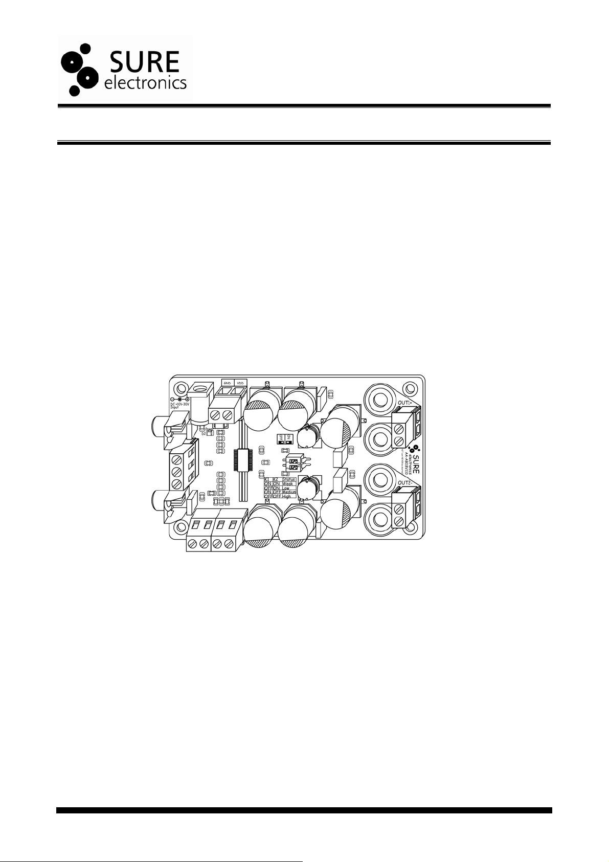
Welcome to use this 2*25W amplifier board from Sure Electronics. Sure has developed
many Class-D amplifiers such as 0.5W, 2W, 8W, 15W, 50W, 100W and one-channel,
dual-channel, four-channel amplifiers to meet different requirements of customers. As a
new member of class-D amplifier series, this 2*25W amplifier board employs TPA3123D2
chip from TI. It supports dual channel amplification and each such channel is rated at 25W
which helps producing state-of-the-art sound quality. The efficiency of the TPA3123D2
eliminates the need for an external heat sink when playing music. Besides, integrating
high-quality SMD and MKP plug-in capacitors ensures Hi-Fi amplification output.
This amplifier can readily be powered by any DC power supply ranging from +10 to 30V.
You can use it to drive any 4Ω or 8Ω passive speakers. It’s an ideal choice for electronic
hobbyists and audio enthusiasts.
FIGURE 1-1 PRODUCT DIAGRAM
© 2004-2009 Sure Electronics Inc.
A-AB018_Ver1.0_Page 1
Page 5
2*25W @4Ω TPA3123 Class-D Audio Amplifier Board
A
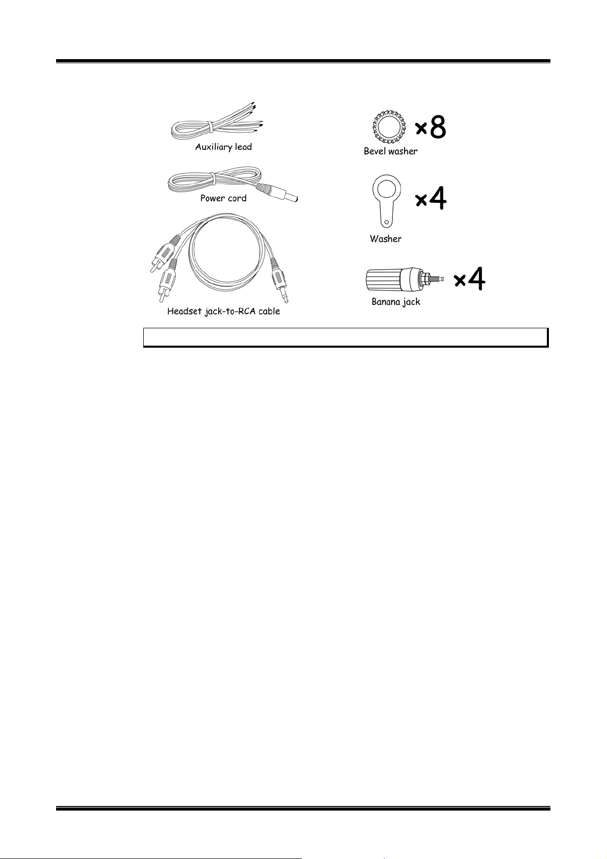
FIGURE 1-2 ACCESSORIES
Note: The diagrams above are used for reference only.
1.2 Features
y A perfect "Class D" architecture
y Fully-bridged stereo output
y Wide power supply range: +10V-30V
y Two kinds of input: line level input and analog audio input
y Frequency response: 20Hz-20KHz(±3dB)
y Signal/Noise Ratio: 100dB(A-Weighted)
y High Output Power
10W @ 8Ω, < 10.0% THD+N
25W @ 4Ω, < 10.0% THD+N
y High Efficiency
85% @ 16W 4Ω
y Audiophile Quality Sound
y Sensitivity and gain adjustable
y Over/under voltage turn off
y Over current protection
y Over temperature protection
1.3 Applications
y Active Subwoofers
y Home Theater Receiver
y Multi-channel Distribution
y Active DVD System
y Mini/Micro Systems
92% @ 8W 8Ω
0.08% THD+N @ 5W 8Ω
0.08% THD+N @ 10W 4Ω
A-AB018_Ver1.0_Page 2
© 2004-2009 Sure Electronics Inc
Page 6

1.4 Benefits
A
y Mounting holes facilitate installation and fixing
y Several wiring methods facilitate connection
y Excellent design of the power ports which allows you to cascade multiple amplifier
y Excellent heat dissipation eliminates the requirement of an extra heat sink
1.5 Quick Start
Suggested connection is shown in figure 1-3.
FIGURE 1-3 CONNECTION SCHEMATIC
Overview
boards (max 4 recommended)
Note: Output signal cannot be bridged again.
Note: Please observe the following steps to complete verification so as to ensure the
products are intact during transit.
1. Open the amplifier package and make sure the product is intact (No missing
or damaged components and no deformation)
2. Please observe the connection schematics when connecting the amplifier
board. Use a nearby sound source, such as MP3 or CD player to have a
trial. This amplifier board can be deemed as qualified if you can hear the
sound corresponding to that sound source.
© 2004-2009 Sure Electronics Inc.
A-AB018_Ver1.0_Page 3
Page 7

2*25W @4Ω TPA3123 Class-D Audio Amplifier Board
A
FIGURE 1-4 CASCADING SCHEMATIC
A-AB018_Ver1.0_Page 4
Note: GND should be grounded or connected to the housing of the device.
© 2004-2009 Sure Electronics Inc
Page 8

A
2.1 Power Connection
To power the amplifier board, use either jack or terminal blocks. On-board diodes can
prevent the consequence of wrong connection of power supply.
FIGURE 2-1 POWER CONNECTION
2*25W @4Ω TPA3123
CLASS-D AUDIO AMPLIFIER BOARD
USER’S GUIDE
Chapter 2. Hardware Detail
TABLE 2-1 POWER CONNECTION
Connector Mark Description
Jack J11 DC 10-30V power supply
Terminal
Blocks
Note:
1. You are allowed to use only one way to power the amplifier board at a time.
2. The maximum supply voltage shall not exceed 30V.
2.2 Input Connections
You may use RCA connectors to input audio signal.
VCC The positive of DC 10-30V power supply
J10
GND The negative of DC 10-30V power supply
© 2004-2009 Sure Electronics Inc.
A-AB018_Ver1.0_Page 5
Page 9

2*25W @4Ω TPA3123 Class-D Audio Amplifier Board
A
FIGURE 2-2 INPUT CONNECTION
TABLE 2-2 INPUT CONNECTION
Connector Mark Channel Description
RCA connector
Terminal Blocks
Note: You are allowed to feed only one group (dual channel) of audio signal to the
amplifier board at a time. Please refer to 2.6 “Gain Setting” for details.
2.3 Output Connections
You can use either terminal blocks or banana connectors to output audio signal. Two
pairs of banana jacks are provided for free.
FIGURE 2-3 OUTPUT CONNECTION 1
J2 Channel 1 Input
J7 Channel 2 Input
J3 (PIN 1) Channel 1 Input
J3 (PIN 2) GND
J3 (PIN 3) Channel 2 Input
A-AB018_Ver1.0_Page 6
© 2004-2009 Sure Electronics Inc
Page 10

Hardware Detail
A
FIGURE 2-4 OUTPUT CONNECTION 2
Note:
1*: not provided here. It can be used together with banana jack (“2” above) facilitating
wiring. You can click
3*: included in the accessories but selectable to be installed.
TABLE 2-3 OUTPUT CONNECTION
Connector Mark Description
Banana Connectors
Terminal blocks
Refer to on-board
descriptions for
connection details
Note: Never connect more than one group of speaker to the audio output.
http://www.sureelectronics.net/goods.php?id=1036 for details.
J1
J5
J6
J9
J4
J8
Positive Output of Channel 1
Negative Output of Channel 1
Negative Output of Channel 2
Positive Output of Channel 2
Output of Channel 1
Output of Channel 2
2.4 Connection with Next Board
J10 and J12 on terminal blocks are used to connect more amplifier boards.
FIGURE 2-5 CONNECTION SCHEMATIC
© 2004-2009 Sure Electronics Inc.
A-AB018_Ver1.0_Page 7
Page 11

2*25W @4Ω TPA3123 Class-D Audio Amplifier Board
A
TABLE 2-4 CONNECTION WITH NEXT BOARD
Connector Mark Description
Connect to Positive (+) of DC 10 to 36V Power Supply (J10) of
the next board
Connect to Negative (GND) of DC 10 to 36V Power Supply (J10)
of the next board
J12
J13
Note:
1. Maximum 4 amplifiers are recommended to be connected in series.
2. Remember to use AWG12-compliant cable or equivalent for series connection.
2.5 Mute Settings
To mute the output audio signal, connect “VDD” and “MUTE” of the terminal block with a
piece of lead. Usually, “MUTE” shall be left unconnected.
FIGURE 2-6 MUTE SETTINGS
VDD
GND
SD Sleep Control
MUTE Mute Control
TABLE 2-5 MUTE SETTINGS
Connector Mark Description
J13 MUTE
Note: Please power the amplifier board with DC 10-30V.
2.6 Sleep Settings
To enable sleep setting, connect “VDD” and “SD” of the terminal block with a piece of
lead. Usually, “SD” shall be left unconnected.
A-AB018_Ver1.0_Page 8
When “MUTE” is connected with “VDD”, both channels will be
muted and enter into idle mode. When connected to ground or
left unconnected, both channels will resume regular operation.
© 2004-2009 Sure Electronics Inc
Page 12

FIGURE 2-7 SLEEP SETTINGS
A
TABLE 2-6 SLEEP SETTINGS
Connector Mark Description
J13
Note: “SD” means that the chip works with low power consumption. “MUTE” means
that the chip normally works with no output.
2.7 Gain Settings
The on-board 2-slide DIP switch, which is marked as “SW1”, is used to set the gain of
amplifier board. The two slides are marked as K1, K2 respectively. The following table
lists the gain values on different settings:
SD
Hardware Detail
When “SD” is connected with “VDD”, both channels will be set to
SLEEP and enter low-power-consumption working mode. When
connected to ground or left unconnected, both channels will
resume regular operation.
© 2004-2009 Sure Electronics Inc.
A-AB018_Ver1.0_Page 9
Page 13

2*25W @4Ω TPA3123 Class-D Audio Amplifier Board
A
FIGURE 2-8 GAIN SETTINGS
TABLE 2-7 GAIN SETTINGS
K1 K2 Gain Level Power Gain (dB) Typical
ON ON Weak 20
OFF ON Low 26
ON OFF Medium 32
OFF OFF High 36
Note:
1. High: Portable MP3/CD player with built-in volume control
2. Different gain levels correspond to different input sensitivities. Improper selection
3. No preamplifier or other devices are needed for gain settings. We won’t assume
2.8 DC Offset
Capacitive coupling output is applied to ensure no DC offset output.
2.9 LED Indicators
This amplifier has one power LED indicator which is marked as “Power (D2)”. The power
indicator will be illuminated in green when power-up. Please refer to the connection
schematics of the board for the LED location.
Settings Amplification Gain
Medium and low: General-purpose use
Weak: Preamplifier with fairly high output signal
will cause the audio distortion or even damage the amplifier board.
any responsibility for the damage caused by connecting extra devices.
A-AB018_Ver1.0_Page 10
© 2004-2009 Sure Electronics Inc
Page 14

FIGURE 2-9 LED INDICATOR
A
2.10 Volume Control
No potentiometer is provided for manually adjusting the volume. The volume control of
sound source like MP3 player or PC can be used to adjust the loudness of the audio
output or a 50KΩ potentiometer can be installed by users themselves, but it may cause
signal attenuation. To compensate that attenuation, adjusting the gain value is required.
You may refer to 2.7 Gain setting for details.
Please be aware that audio clippings may occur to some portable players because of
the audio source not the amplifier itself. Please increase the input gain of amplifier
board.
2.11 Notes
In order to protect amplifier board and extend its service lifetime, please read the
following warnings carefully since warranties will be voided if you do not observe the
following warnings:
Warning 1:
Quality-related issues caused by potentiometers installed by buyers.
Warning 2:
In order to achieve a better sound quality, please use stable power supply since a bad or
unstable power supply may worsen the sound quality or even cripple the amplifier board.
Warning 3:
Never equip a pre-amplifier to the audio input since the amplifier itself has powerful
amplification ability and a high signal input will burn out the amplifier chip.
Warning 4:
In order to protect amplifier and speaker, please turn the volume output to the minimum
when hooking up the amplifier and you may readjust the volume when you are sure that
the amplifier is functioning properly.
Hardware Detail
© 2004-2009 Sure Electronics Inc.
A-AB018_Ver1.0_Page 11
Page 15
2*25W @4Ω TPA3123
A
CLASS-D AUDIO AMPLIFIER BOARD
USER’S GUIDE
Chapter 3. Electrical Characteristics
Following table lists all typical data. For full specification, please refer to the TI data sheet
of TPA3123 chip.
=20℃, DC24V, f=1000Hz, Sine wave input, RL=4Ω, Gain=20dB (unless otherwise
T
A
stated)
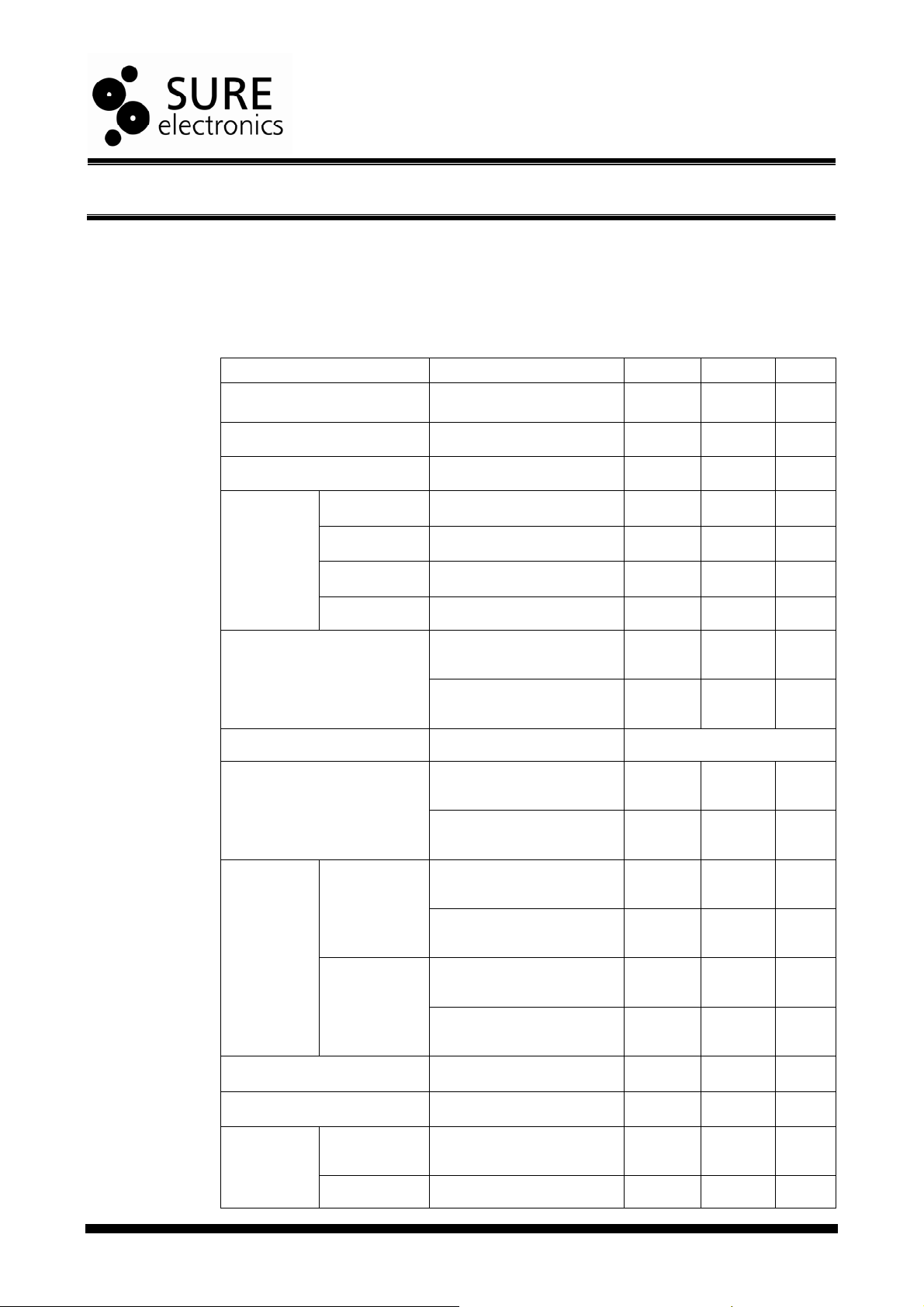
TABLE 3-1 ELECTRICAL CHARACTERISTICS
Parameter Condition Min. Typ. Max.
Supply Voltage - 10V - 30V
Supply Current - - - 2A
Signal/Noise Ratio - 90dB 100dB -
Gain=36dB
Input
Sensitivity
THD+N*
Frequency Range -
Efficiency
Output
Power
Gain=32dB
Gain=28dB
Gain=20dB
THD+N<1%
THD+N<10%
VDD=24V, RL=4Ω,
Pout=10W
V
=24V, RL=8Ω,
DD
Pout=5W
VDD=24V, RL=4Ω,
=16W
P
out
V
=24V, RL=8Ω,
DD
P
out
VDD=24V, RL=4Ω,
f=1000Hz
V
=24V, RL=8Ω,
DD
f=1000Hz
VDD=24V, RL=4Ω,
f=1000Hz
V
=24V, RL=8Ω,
DD
f=1000Hz
- 0.100V 0.117V -
- 0.180V 0.196V -
- 0.380V 0.396V -
- 0.780V 0.803V -
- 0.08% -
- 0.08% -
20Hz-20KHz(±3dB)
- 85% -
=8W
- 92% -
- 16W -
- 8W -
- 20W -
- 10W -
Input Impedance - - 60K -
Minimum Load - 3.2Ω - -
High-level
SD, MUTE*
A-AB018_Ver1.0_Page 12
input voltage
Low-level - - - 0.8V
- 2V - -
© 2004-2009 Sure Electronics Inc.
Page 16

2*25W@4Ω TPA3123 Class-D Audio Amplifier Board
A
Input voltage
Channel Separation* - -50dB -60dB -
SW1 - K1 K2 - - -
Weak - ON ON 18 dB 20 dB 22 dB
Power
Gain*
Operating Temperature - 0℃ 20℃ 50℃
Storage Temperature - -20℃ 20℃ 105℃
Thermal Shutdown* - - 150℃ -
Note: *The chip specifications from TI’s TPA3123 Data Sheet.
Low - OFF ON 24 dB 26 dB 28 dB
Medium - ON OFF 30 dB 32 dB 34 dB
High - OFF OFF 34 dB 36 dB 38 dB
© 2004-2009 Sure Electronics Inc.
A-AB018_Ver1.0_Page 13
Page 17

2*25W @4Ω TPA3123
A
CLASS-D AUDIO AMPLIFIER BOARD
USER’S GUIDE
Chapter 4. Mechanical Drawing
FIGURE 4-1 MECHANICAL DRAWING
A-AB018_Ver1.0_Page 14
© 2004-2009 Sure Electronics Inc.
Page 18

2*25W @4Ω TPA3123
A
CLASS-D AUDIO AMPLIFIER BOARD
USER’S GUIDE
Chapter 5. Appendix
FIGURE 5-1 SCHEMATIC
VCC
U1 TPA3123/HTSSOP
1
J2
CH1
1 2
J7
CH2
1 2
J10 CON2
1
2
J11 DJ005B
J12 CON2
2
1
J13 CON2
1
2
C4 1uF/50V
C7 1uF/50V
C10 0.22uF/MKP
VCC
R3
4.7K
D2
LED/G
R7
100K
SD
C30
1uF/50V
SD
MUTE
C9 1uF/50V
VCC
C15 1uF/50V
J3
1
2
3
CON4
D1 SS34
1 2
1
2
3
VCC
SD
MUTE
R8
10K
PVCCL1
2
SD
3
PVCCL2
4
MUTE
5
LIN
6
RIN
7
BYPASS
8
AGND1
9
AGND2
10
PVCCR1
11
VCLAMP
12 13
PVCCR2 PGNDR1
VCC
PIN1
PIN3
C18
C17
C16
0.1uF
1uF/50V
1uF/50V
VCC VCC
12
12
C23
C22
+
+
470uF/35V
470uF/35V
Note: The above schematic is used for reference only. There might be a tiny difference
in production batch.
靠近芯片
PGNDL2
PGNDL1
AVCC2
AVCC1
PGNDR2
VCC
1
+
2
LOUT
BSL
GAIN0
GAIN1
BSR
ROUT
C24
470uF/35V
24
23
22
C3 0.22uF
21
20
19
18
17
C13 0.22uF
16
15
14
VCC
VCC
12
GAINA0
GAINA1
C25
+
470uF/35V
PIN10
PIN12
C19
0.1uF
靠近芯片
VCC
C20
1uF/50V
C21
1uF/50V
C26
0.22uF//MKP
C8
0.1uF
VCC
L1 33uHC1 0.22uF/MKP
VCC
L2 33uH
GAINA0
GAINA1
VCC
C27
0.22uF//MKP
C28
0.1uF
J1 OUT1+
C2 470uF/35V
+
1 2
C5
R1
4.7K
R2
4.7K
VCC
VCC
C29
0.1uF
0.47uF/MKP
C11
0.47uF/MKP
R5 10K
R4 10K
C6
1uF/50V
C12
1uF/50V
1 2
最大瞬间电流
SW1
124
SW DIP-2/SM
+
C14 470uF/35V
5A
3
1
1
J5
OUT1OUT1-
J6
1
1
J9 OUT1+
R6 0R
J4
CON2
J8
CON2
2
1
2
1
© 2004-2009 Sure Electronics Inc.
A-AB018_Ver1.0_Page 15
Page 19

2*25W @4Ω TPA3123
A
CLASS-D AUDIO AMPLIFIER BOARD
USER’S GUIDE
Chapter 6. Contact Us
Sure Electronics Co., Ltd.
5F, Zone A,
Qinhuai Technology Innovation Center
105-2 DaMing Rd (ZIP:210022)
Nanjing
P.R.China
Tel: +86-13601408832 (For technical questions only)
+86-25-66606340 (English service, from GMT1-10AM)
Fax: +86-25- 66606341-866
Website: www.sure-electronics.com
www.sure-electronics.net
A-AB018_Ver1.0_Page 16
© 2004-2009 Sure Electronics Inc.
 Loading...