

Page 1

2*2W @4Ω PAM8803 Class-D
Audio Amplifier Board
User’s Guide
© 2004-2010 Sure Electronics Inc. AA-AB32131&AA-AB32133_Ver1.0
Page 2

2*2W @4Ω PAM8803 CLASS-D
A
AUDIO AMPLIFIER BOARD
USER’S GUIDE
Table of Contents
Chapter 1. Overview ..........................................................................................................1
1.1 Overview .............................................................................................................. 1
1.2 Features ............................................................................................................... 2
1.3 Applications......................................................................................................... 3
1.4 Benefits ................................................................................................................ 3
1.5 Quick Start ........................................................................................................... 3
Chapter 2. Hardware Detail ...............................................................................................5
2.1 Power Connection............................................................................................... 5
2.2 Input Connection................................................................................................. 6
2.3 Output Connections............................................................................................ 6
2.4 Mute Settings....................................................................................................... 7
2.5 Sleep Settings ..................................................................................................... 9
2.6 Volume Control Settings .................................................................................. 12
2.7 Volume Control ................................................................................................. 12
2.8 LED Indicator..................................................................................................... 14
2.9 Notes .................................................................................................................. 14
Chapter 3. Electrical Characteristics .............................................................................15
Chapter 4. Mechanical Drawing......................................................................................17
Chapter 5. Appendix........................................................................................................18
Chapter 6. Contact Us .....................................................................................................19
© 2004-2010 Sure Electronics Inc.
A-AB32131&AA-AB32133_Ver1.0_Page i
Page 3

2*2W @4Ω PAM8803 Class-D Audio Amplifier Board
A
NOTES:
Product Version : Ver 1.0
Document Version : Ver 1.0
A-AB32131&AA-AB32133_Ver1.0_Page ii
© 2004-2010 Sure Electronics Inc
Page 4
A
1.1 Overview
2*2W @4Ω PAM8803 CLASS-D
AUDIO AMPLIFIER BOARD
USER’S GUIDE
Chapter 1. Overview
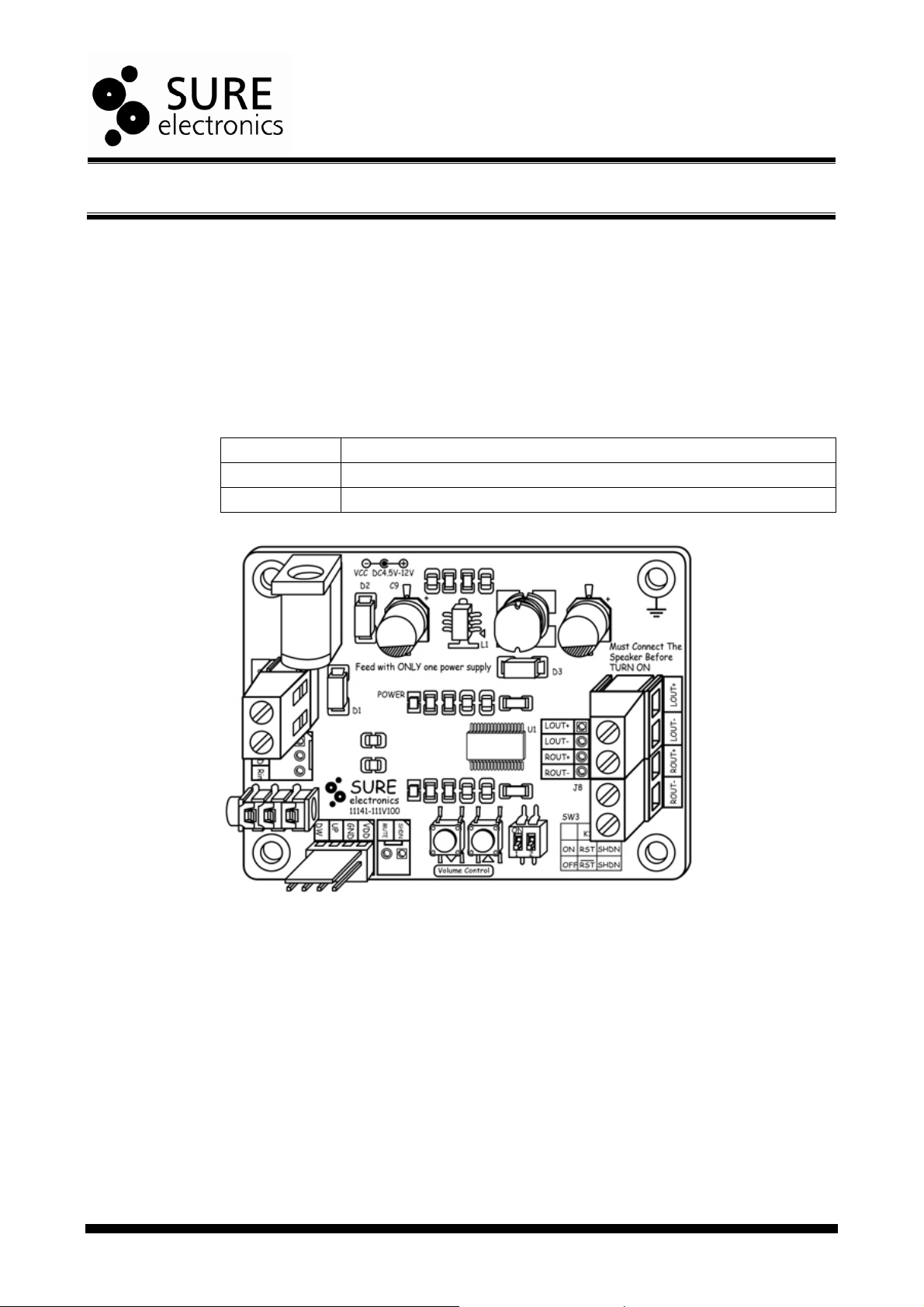
Thanks for using 2*2W audio amplifier board series. Each member is a high-quality
dual-channel class-D audio amplifier board capable of delivering 2W per channel of
output power into a 4 load. It employs
volume control and low THD+N, allowing it to produce high-quality sound reproduction.
It’s especially suitable for small speakers. This amplifier board can also be used to drive
passive 4 or 8 speakers.
TABLE 1-1 2*2W AUDIO AMPLIFIER BOARD SERIES
Product No. Product Name
AA-AB32131 2*2W @4 PAM8803 Class-D Audio Amplifier Full-featured Board
AA-AB32133 2*2W @4 PAM8803 Class-D Audio Amplifier Simple Board
FIGURE 1-1 OVERVIEW OF AA-AB32131
PAM’s PAM8803 IC which offers 64-step digital
© 2004-2010 Sure Electronics Inc.
A-AB32131&AA-AB32133_Ver1.0_Page 1
Page 5
2*2W @4Ω PAM8803 Class-D Audio Amplifier Board
A
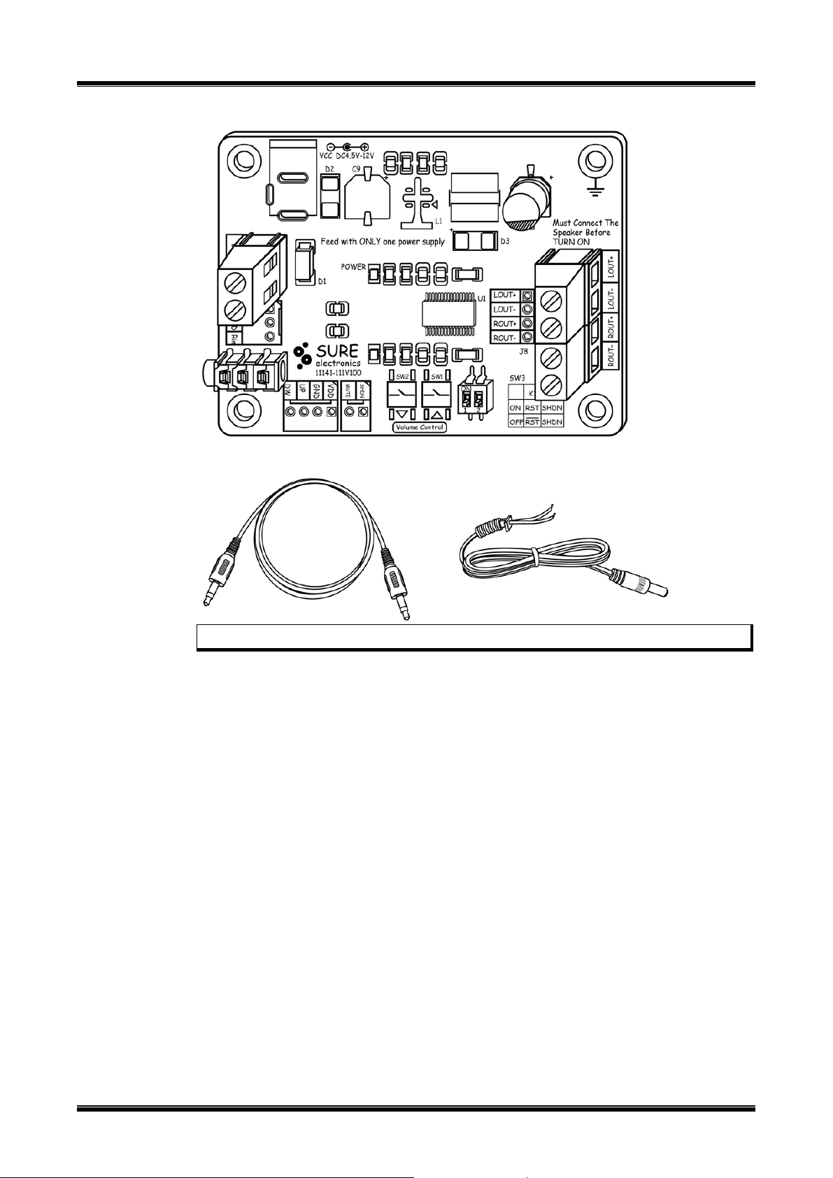
FIGURE 1-2 OVERVIEW OF AA-AB32133
FIGURE 1-1 ACCESSORY
1.2 Features
Note: All the diagrams in this manual are for reference only.
y A perfect “Class D” architecture
y Fully-bridged stereo output
y power supply:
AA-AB32131:
Wide power supply range: DC4.5V to12V via a power port
Two to three AA batteries
AA-AB32133:
Two to three AA batteries or DC2.5V to 4.0V via a terminal block
y Two kinds of input:
Line level input via 2510 connector
Audio input via 3.5 headphone jack
y Frequency response: 20Hz to 20KHz(±3dB)
y Signal/Noise Ratio: 85dB (f=22 to 22KHz, THD=1%)
y High Output Power
1.2W @ 8, < 10.0% THD+N
2.0W @ 4, < 10.0% THD+N
y High Efficiency
85% @ 1.2W 8
or DC2.5V to 4.0V via a terminal block
A-AB32131&AA-AB32133_Ver1.0_Page 2
© 2004-2010 Sure Electronics Inc
Page 6
y Audiophile Quality Sound
A
y Volume control:
y Over/under voltage turn off
y Over current protection
y Over temperature protection
1.3 Applications
y Home Active Speaker
y Home Theater Receiver
y Multi-channel Distribution
y Active DVD System
y Mini/micro Systems
1.4 Benefits
y Mounting holes facilitate installation and fixing
y Several wiring methods facilitate connection
y Excellent heat dissipation eliminate the requirement of an extra heat sink
y Tactile switches for volume control are adjustable
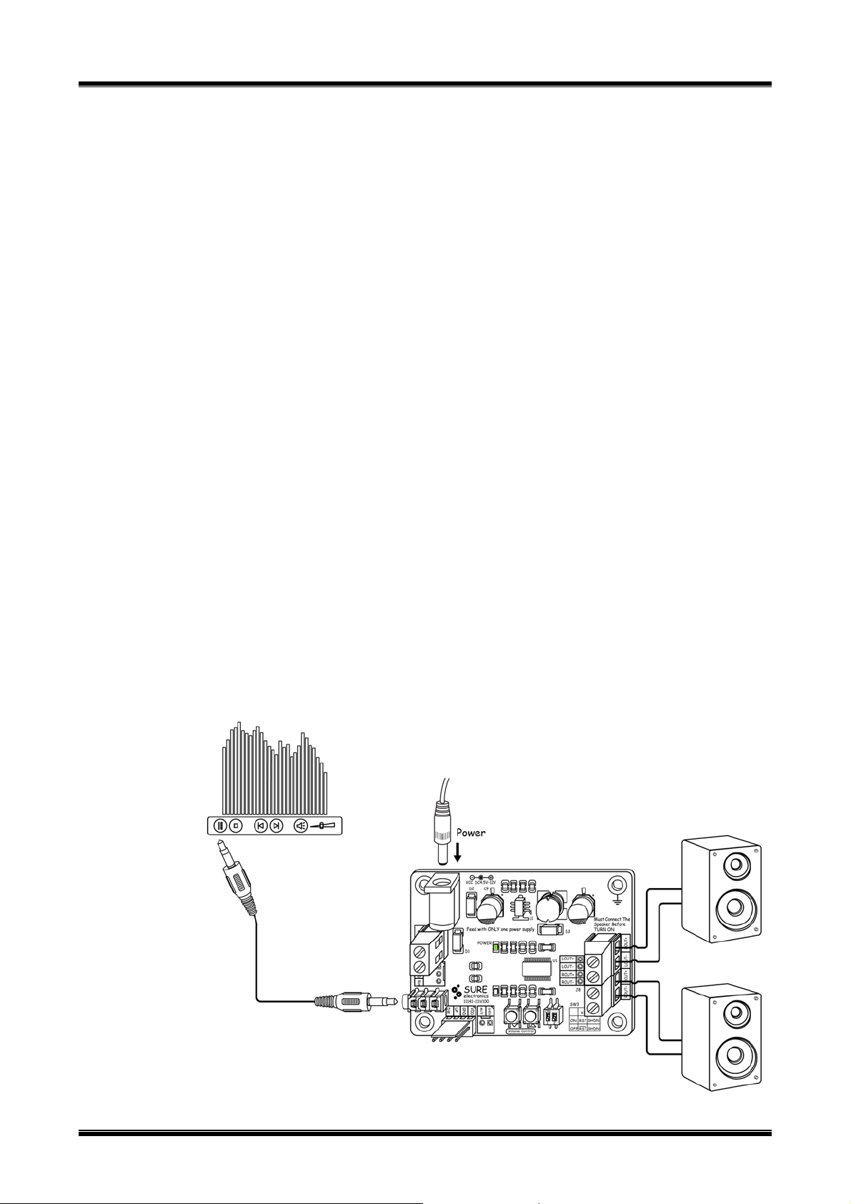
1.5 Quick Start
Suggested connection is shown in figure 1-4 and figure 1-5.
FIGURE 1-4 CONNECTION (AA-AB32131)
Overview
88% @ 2.0W 4
0.19% THD+N @ 0.5W 8
0.17% THD+N @ 1.0W 4
Volume control buttons
External rotary encoder daughter board
© 2004-2010 Sure Electronics Inc.
A-AB32131&AA-AB32133_Ver1.0_Page 3
Page 7
2*2W @4Ω PAM8803 Class-D Audio Amplifier Board
A
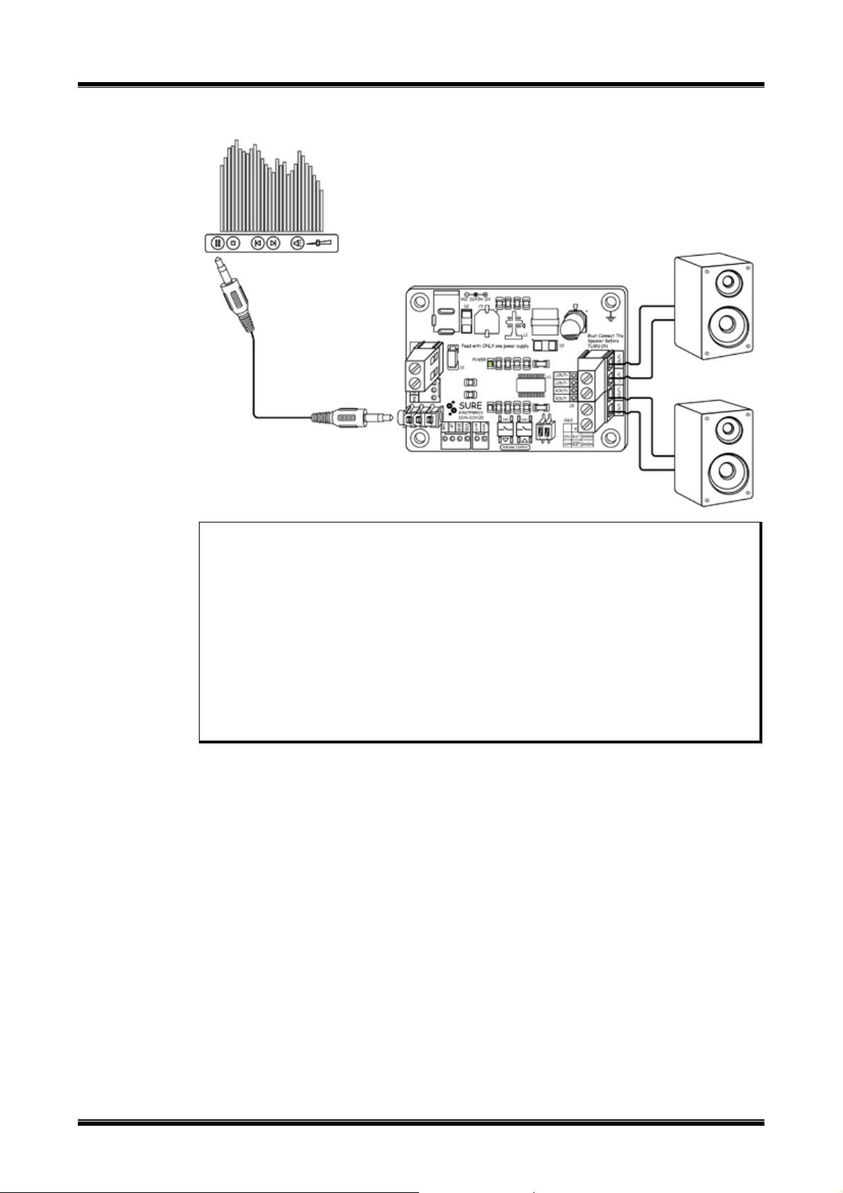
FIGURE 1-5 CONNECTION (AA-AB32133)
Note: Please observe the following steps to complete verification so as to ensure the
products are intact during transit.
1. Open the amplifier package and make sure the product is intact (No
missing or damaged components and no deformation)
2. Please observe the connection schematics when connecting the amplifier
board. Use a nearby sound source, such as MP3 or CD player to have a
trial. This amplifier board can be deemed as qualified if you can hear the
sound corresponding to that sound source.
3. Ensuring the long life time, load connection is recommended before the
power is turned on.
4. GND should be grounded or connected to the housing of the device.
5. The mounting holes of this product should be grounded.
A-AB32131&AA-AB32133_Ver1.0_Page 4
© 2004-2010 Sure Electronics Inc
Page 8

A
2.1 Power Connection
To power the amplifier board, use either jack or terminal blocks. On-board diodes can
prevent the consequence of wrong connection of power supply.
FIGURE 2-1 POWER CONNECTION (AA-AB32131)
2*2W @4Ω PAM8803 CLASS-D
AUDIO AMPLIFIER BOARD
USER’S GUIDE
Chapter 2. Hardware Detail
FIGURE 2-2 POWER CONNECTION (AA-AB32133)
TABLE 2-1 POWER PORT
Connector Mark Description
Jack (AA-AB32131) J9 DC 4 to 12 power supply
Terminal Blocks
(AA-AB32131,
AA-AB32133)
Vbatt The positive of 2 to 3 AA batteries
J1
GND The negative of 2 to 3 AA batteries
© 2004-2010 Sure Electronics Inc.
A-AB32131&AA-AB32133_Ver1.0_Page 5
Page 9

2*2W @4Ω PAM8803 Class-D Audio Amplifier Board
A
Note:
1. You are allowed to use only one way to power the amplifier board at a time.
2. The maximum supply voltage shall not exceed 14V.
One less than 6V battery or more connected in series can be used to power the
3.
board. The minimum limited number is 2 AA batteries.
2.2 Input Connection
You may use 3.5mm headphone jack for audio signal input or use 2510 socket’s
mounting holes for line level audio input.
FIGURE 2-3 INPUT CONNECTION (AA-AB32131)
FIGURE 2-4 INPUT CONNECTION (AA-AB32133)
TABLE 2-2 INPUT PORT
Connector Mark Description
Mounting Holes (J4)
3.5mm Headphone Jack J7 Left and Right Channel Input
Note: You are allowed to feed only one group (dual channel) of audio signal to the
amplifier board at a time.
2.3 Output Connections
You may use either terminal blocks for audio signal output or use mounting holes when
this board is used as a daughter board.
Lin Left Channel Input
GND GND
Rin Right Channel Input
A-AB32131&AA-AB32133_Ver1.0_Page 6
© 2004-2010 Sure Electronics Inc
Page 10

FIGURE 2-5 OUTPUT CONNECTION (AA-AB32131)
A
FIGURE 2-6 OUTPUT CONNECTION (AA-AB32133)
Hardware Detail
TABLE 2-3 OUTPUT PORT
Connector Mark Description
Mounting holes (J8)
Terminal Blocks*
Note:
2.4 Mute Settings
The hole for MUTE is reserved on the board. To mute the output audio signal, connect
“GND” and “MUTE” of the terminal block with a piece of lead. Usually, “MUTE” shall be
left unconnected.
LOUT+ Positive Output of Left Channel
LOUT- Negative Output of Left Channel
ROUT+ Negative Output of Right Channel
ROUT- Positive Output of Right Channel
J2 Output of Left Channel
J3 Output of Right Channel
1. Never connect more than one group of speaker to the audio output.
2. * Refer to on-board descriptions for connection details.
© 2004-2010 Sure Electronics Inc.
A-AB32131&AA-AB32133_Ver1.0_Page 7
Page 11

2*2W @4Ω PAM8803 Class-D Audio Amplifier Board
A
FIGURE 2-7 MUTE SETTINGS (AA-AB32131)
FIGURE 2-8 MUTE SETTINGS (AA-AB32133)
A-AB32131&AA-AB32133_Ver1.0_Page 8
© 2004-2010 Sure Electronics Inc
Page 12

TABLE 2-4 MUTE SETTINGS
A
Connector Mark Description
Note: Never connect MUTE to any power supply or voltage higher than +5V.
2.5 Sleep Settings
Two kinds of connection and installation are available: mounting holes and DIP switches.
To enable sleep settings, connect “GND” and “SHDN” of the terminal block with a piece
of lead. Usually, “SHDN” shall be left unconnected.
FIGURE 2-9 SLEEP SETTINGS (AA-AB32131)
J6
MUTE
Hardware Detail
When “MUTE” is connected with “GND”, both channels will be
muted and enter into idle mode. When connected with high level
or left unconnected, both channels will resume regular operation.
© 2004-2010 Sure Electronics Inc.
A-AB32131&AA-AB32133_Ver1.0_Page 9
Page 13

2*2W @4Ω PAM8803 Class-D Audio Amplifier Board
A
FIGURE 2-10 SLEEP SETTINGS (AA-AB32133)
TABLE 2-5 SLEEP SETTINGS
Connector Mark Description
When “SHDN” is connected with “GND”, the chip will be set to
J6
Settings of DIP switches are shown as follows.
SHDN
SLEEP and enter low-power-consumption working mode. When
“SHDN” is connected with high level or left unconnected, the chip
will resume regular operation.
A-AB32131&AA-AB32133_Ver1.0_Page 10
© 2004-2010 Sure Electronics Inc
Page 14

Hardware Detail
A
FIGURE 2-11 SETTINGS OF DIP SWITCHES (AA-AB32131)
FIGURE 2-12 SETTINGS OF DIP SWITCHES (AA-AB32133)
TABLE 2-6 SETTINGS OF DIP SWITCHES
SHDN Settings
K2 Function
ON Sleep mode
OFF Working mode
© 2004-2010 Sure Electronics Inc.
A-AB32131&AA-AB32133_Ver1.0_Page 11
Page 15

2*2W @4Ω PAM8803 Class-D Audio Amplifier Board
A
Note: SLEEP means that the chip works with low power consumption. MUTE means
that the chip normally works with no output.
2.6 Volume Control Settings
On-board 2-slide DIP switches marked as “SW3” is used for volume control. K1 is used
to set volume and K2 used to set the SHDN of the chip.
FIGURE 2-13 VOLUME CONTROL SETTINGS (AA-AB32131)
TABLE 2-7 VOLUME CONTROL SETTINGS (AA-AB32131)
K1 Function
ON Disable the tactile switches
OFF Enable the tactile switches for volume control
Note: When K1 is ON, the chip will amplify the audio signal with 4dB gain and the tactile
switches are disabled.
2.7 Volume Control
Two kinds of control input are provided to control volume: on-board tactile switches and
external rotary encoder control daughter board interface.
A-AB32131&AA-AB32133_Ver1.0_Page 12
Volume Control Settings
© 2004-2010 Sure Electronics Inc
Page 16

FIGURE 2-14 VOLUME CONTROL (AA-AB32131)
A
Hardware Detail
TABLE 2-8 VOLUME CONTROL (AA-AB32131)
Connector Mark Description
SW1 UP Tactile Switch for Volume Increase
SW2 DOWN Tactile Switch for Volume Decrease
VDD 4.2V Voltage Output
J5
TABLE 2-9 CORRESPONDING GAIN OF EACH STEP OF VOLUME CONTROL
Step Gain(dB) Step Gain(dB) Step Gain(dB) Step Gain(dB)
1 -75.0 17 4.8 33 11.2 49 17.6
2 -39.7 18 5.1 34 11.6 50 18.0
3 -34.0 19 5.5 35 12.0 51 18.4
4 -28.2 20 5.9 36 12.3 52 18.8
5 -22.4 21 6.3 37 12.7 53 19.2
6 -16.5 22 6.7 38 13.2 54 19.6
7 -10.5 23 7.1 39 13.6 55 20.0
8 -8.0 24 7.5 40 14.0 56 20.4
9 -5.5 25 7.9 41 14.4 57 20.9
10 -2.9 26 8.3 42 14.8 58 21.3
11 -0.4 27 8.7 43 15.2 59 21.7
12 1.1 28 9.1 44 15.6 60 22.1
13 2.6 29 9.6 45 16.0 61 22.5
14 3.6 30 10.0 46 16.4 62 22.9
15 4.0 31 10.4 47 16.8 63 23.4
16 4.4 32 10.7 48 17.2 64 23.8
GND GND
UP Volume Increase Input (Low Level Valid)
DOWN Volume Decrease Input (Low Level Valid)
© 2004-2010 Sure Electronics Inc.
A-AB32131&AA-AB32133_Ver1.0_Page 13
Page 17

2*2W @4Ω PAM8803 Class-D Audio Amplifier Board
A
2.8 LED Indicator
This amplifier has one power LED indicator which is marked “Power (D4)”. The power
indicator will be illuminated in green when power-up. Please refer to the connection
schematic of the board for the LED location.
2.9 Notes
In order to protect amplifier board and extend its service lifetime, please read the
following warnings carefully since warranties will be voided if you do not observe the
following warnings:
Warning 1:
Quality-related issues caused by potentiometers installed by buyers.
Warning 2:
In order to achieve a better sound quality, please use stable power supply since a bad or
unstable power supply may worsen the sound quality or even cripple the amplifier board.
Warning 3:
Never equip a pre-amplifier to the audio input since the amplifier itself has powerful
amplification ability and a high signal input will burn out the amplifier chip.
Warning 4:
In order to protect amplifier and speaker, please turn the volume output to the minimum
when hooking up the amplifier and you may readjust the volume when you are sure that
the amplifier is functioning properly.
A-AB32131&AA-AB32133_Ver1.0_Page 14
© 2004-2010 Sure Electronics Inc
Page 18

2*2W @4Ω PAM8803 CLASS-D
A
AUDIO AMPLIFIER BOARD
USER’S GUIDE
Chapter 3. Electrical Characteristics
Following table lists all typical data. For full specification, please refer to the
sheet of PAM8803 chip.
T
=20 , f=1000Hz RL=4, f=1000Hz, Sine wave input, R℃
A
stated)
FIGURE 3-1 ELECTRICAL CHARACTERISTICS
Parameter Condition Min. Typ. Max.
AA-AB32131 - 4V - 12V
Supply Voltage
Quiescent
Current
AA-AB32131
AA-AB32133
AA-AB32131
AA-AB32133
- 2.5V - 4.5
DC12V, NO load - 100mA -
MUTE=0 - 10mA 40mA
2AA batt, NO load - 20mA -
MUTE=0 - 10mA 20mA
=4 (unless otherwise
L
PAM’s data
Signal/Noise Ratio - - 85dB -
Input Sensitivity A=0dB - 0.720V -
RL=4, Pout=1W - 0.17 % -
THD+N*
RL=8, Pout=0.5W - 0.19 % -
Frequency Range - 20HZ to 20KHz (±3dB)
RL=4, Pout=2.6W - 88% -
Efficiency
RL=8, Pout=1.5W - 85% -
RL=4, f=1000Hz - 1.5W -
THD+N<1%
Output
Power
THD+N<10%
Input Impedance - - 60K -
Minimum Load - 3.2ohm - -
SHUD, UP,
DOWM,
MUTE*
High-level input
voltage
Low-level input
voltage
RL=8, f=1000Hz - 1.0W -
RL=4, f=1000Hz - 2.0W -
RL=8, f=1000Hz - 1.2W -
- 1.2V - -
- - - 0.5V
Channel Separation* Po=1W, RL=4ohm 60dB 80dB -
© 2004-2010 Sure Electronics Inc.
A-AB32131&AA-AB32133_Ver1.0_Page 15
Page 19

2*2W @4Ω PAM8803 Class-D Audio Amplifier Board
A
Volume
Power Gain*
Operating Temperature - 0℃ 20℃ 70℃
Storage Temperature - -20℃ 20℃ 105℃
Thermal Shutdown* - - 150℃ -
Note: *The chip specifications from PAM’s PAM8803 Data Sheet.
Adjustable
Volume not
adjustable
K1=OFF -75dB - 23.8dB
K1=ON - 2.6dB -
A-AB32131&AA-AB32133_Ver1.0_Page 16
© 2004-2010 Sure Electronics Inc
Page 20

2*2W @4Ω PAM8803 CLASS-D
A
AUDIO AMPLIFIER BOARD
USER’S GUIDE
Chapter 4. Mechanical Drawing
FIGURE 4-1 MECHANICAL DRAWING
© 2004-2010 Sure Electronics Inc.
A-AB32131&AA-AB32133_Ver1.0_Page 17
Page 21

2*2W @4Ω PAM8803 CLASS-D
A
AUDIO AMPLIFIER BOARD
USER’S GUIDE
Chapter 5. Appendix
FIGURE 5-1 SCHEMATIC
OUT_L-
OUT_L+
J2
1
2
CON2
J7
1
2
3
PHONEJACK STEREO
C3 1uF/50V
INL
C5 1uF/50V
MUTE
SHDN
VCC
VCC
12
C1
C2
+
10uF/25V/TAN
1uF/50V
OUT_R+
U1
1
8
19
+OUT_L
-OUT_L
INL
VREF
MUTE
SHDN
91011
INL
INR
2
34567
18
VDD
GND
PVDD
PGND
PGND
+OUT_R
24
-OUT_R
C4 1uF/50V
17
INR
PAM8803
14
UP
13
DN
15
NC
NC
RST
NC
NC
VDD
PGND
PGND
12
16
202122
23
VCC
RST
VCC
12
C6
C7
+
1uF/50V
10uF/25V/TAN
OUT_R-
1
2
J3 CON2
INR
4
SW1
123
4
123
SW2
DN
UP
VCC
R1
SW3
6.8K
RST
SHDN
124
SW DIP-2/SM
3
VCC
VCC
R7
6.8K
DN
UP
VCC
MUTE
D1
J1
1
2
SS14
CON2
J5 con4
4
3
2
1
J4
1
2
3
CON3
J6
1
2
CON2
INL
INR
VCC
R8
6.8K
VCC
R2
6.8K
SHDN
VCC
J9 DJ005B
12
+
C9
100uF/16V
12
C11
104
AX3022/SOT89-5L
R3 104
U2
5
VCC
SS14
1
2
3
D2
L1 33uH
R5
4
EN
FBSWVSS
312
FB
6.8K
D3
FB
R6
SS14
1.5K
Note: The schematic is for reference only.
12
+
C8
220uF/10V
C10
1uF/50V
VCC
R4
470R
D4
LED/G
OUT_L+
OUT_LOUT_ROUT_R+
J8 con4
4
3
2
1
A-AB32131&AA-AB32133_Ver1.0_Page 18
© 2004-2010 Sure Electronics Inc.
Page 22

2*2W @4Ω PAM8803 CLASS-D
A
AUDIO AMPLIFIER BOARD
USER’S GUIDE
Chapter 6. Contact Us
Sure Electronics Co., Ltd.
East zone, 3F, Building 6
Jingang Technology Innovation Center
No.108 Ganjiabian Rd (ZIP: 210000)
Qixia District
Nanjing
P.R.China
Tel: +86-25-68154800-860
Fax: +86-25-68154891-832
Website: www.sure-electronics.com
Email: customerservice@sure-electronics.com
© 2004-2010 Sure Electronics Inc.
A-AB32131&AA-AB32133_Ver1.0_Page 19
 Loading...