

Page 1
5V-16V Linear Power Supply Kit User’s Guide
Note:
Overview
This kit is designed to fill the need for a power supply which can be connected to the mains
electrical supply of your house and which can provide the range of DC voltages that are
required for basic electronic projects. The circuit is basic but it will satisfy the requirements
of most electronic kit users especially when starting out. Two DC voltage outputs are
available. One is a fixed regulated 5V for TTL use. The other output is variable from 5V
upwards. The maximum output voltage depends on the input voltage. The specified
maximum input DC voltage to the regulator is 16V. The minimum input voltage must be 2V
higher than the regulated output voltage.
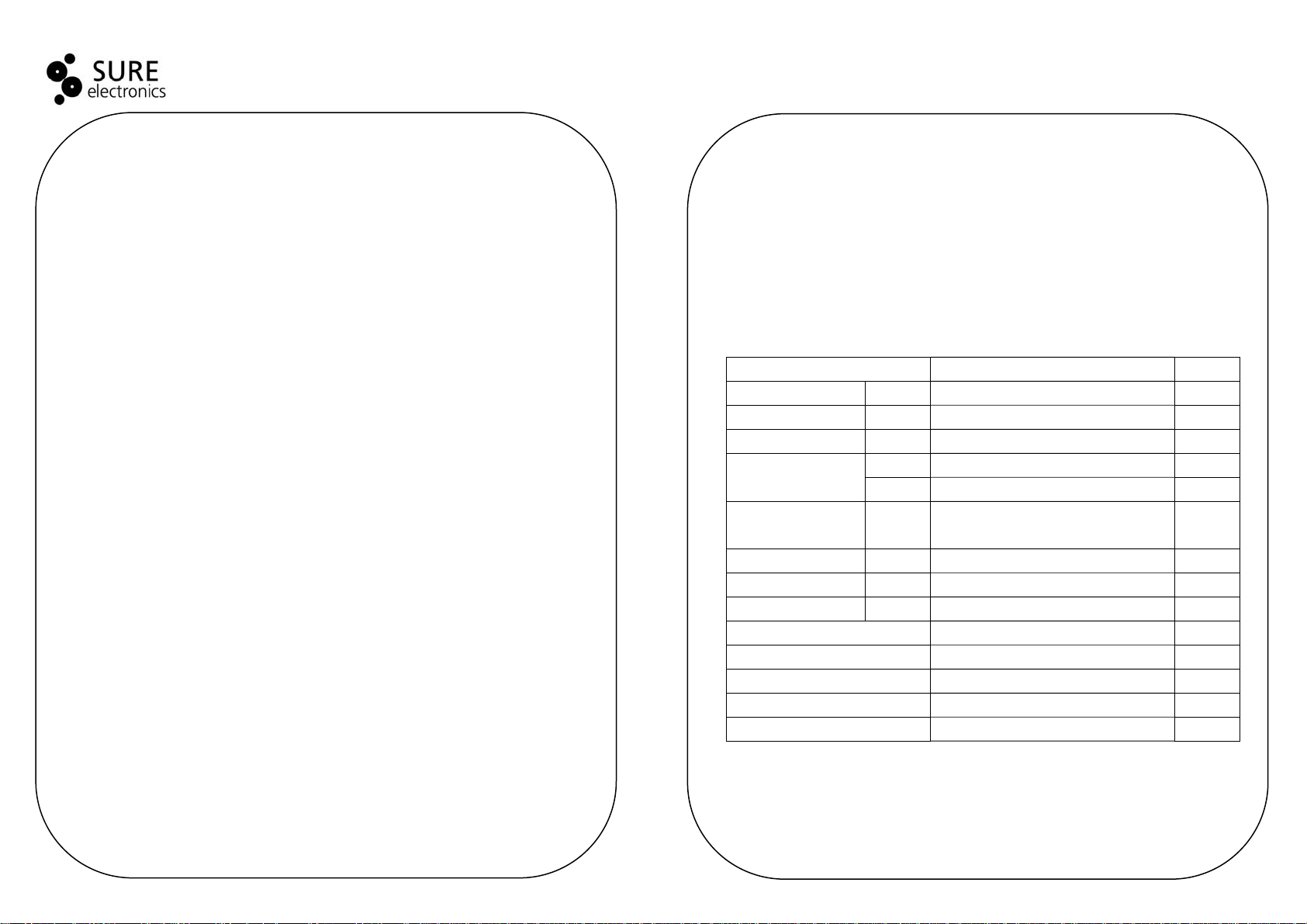
Item Description Quantity
Electrolytic Capacitor C1 1000uF/35V 1
Voltage Regulator IC U1,U2 LM7805 2
LED D1 5mm 1
Resistor
Monoblock
Input Jack J2 - 1
Bridge Rectifier W02 W02 1
Terminal Block J3, J4 2 pole 2
Printed Circuit Board 79.40(L) × 50.20(W) × 1.60(H) ±0.2mm 1
Potentiometer 500R, linear 1
Heat Sink HS-103 2
Screw M3mm×6mm 2
Nut M3mm 2
R1 390R, carbon 5% (orange, white, brown) 1
R2 250R 1
C2, C3,
C4, C5
100nF(104) 4
Application
Provide DC voltages for basic electronic projects
4
1
Page 2
5V-16V Linear Power Supply Kit User’s Guide
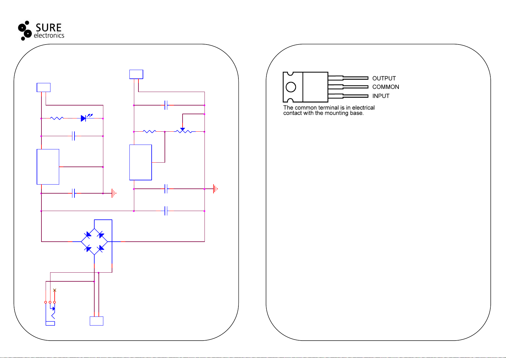
Circuit Diagram
J3
1
2
CON2
R1
390R
12
GND
2
7805AE/TO-220
Vin +5V
1 3
J2
U1
12
4
321
DJ005B
C3
C2
100nf
100nf
D1
J4
-+
W02
1
3
7805AE/TO-220
2
Pin Definition of 7805
1
2
CON2
12
R2
C5
250R
100nf
2
13
R3
500R
What to Do If It Does Not Work
An LED has been put into the output of the fixed 5V regulator to indicate that the circuit is
working. (It may be left out of the circuit if you do not want it.) Poor soldering is the most
likely reason that the circuit does not work. Check all solder joints carefully under a good
GND
2
Vin +5V
1 3
U2
12
C4
100nf
+
12
light. Next, check that all components are in their correct position on the PCB. Thirdly, follow
the track with a voltmeter to check the potential differences at various parts of the circuit.
Contact Us
Sure Electronics Co., Ltd.
East zone, 3F, Building 6
Jingang Technology Innovation Center
No.108 Ganjiabian Rd (ZIP: 210000)
C1
1000uf
Qixia District
Nanjing
P.R.China
Tel: +86-25-68154800-860
Fax: +86-25-68154891-832
Website: www.sure-electronics.com
Email: customerservice@sure-electronics.com
1
2
J1
CON2
2 3
 Loading...