

Page 1

3216 Bicolor LED 3mm (5mm)
Dot Matrix Display
Information Board
User’s Guide
2004-2009 Sure Electronics Inc. DE-DP14112&DE-DP14211 _Ver1.1
Page 2

3216 BICOLOR LED 3MM
(5MM) DOT MATRIX DISPLAY
INFOMATION BOARD
USER’S GUIDE
2004-2009 Sure Electronics Inc.
DE-DP14112&DE-DP14211_Ver1.1_Page i
Table of Contents
Chapter 1. Overview ..........................................................................................................1
1.1 Overview .............................................................................................................. 1
1.2 Quick Start ........................................................................................................... 3
1.2.1 Connection of One Info Board and The Driver Board .................................... 3
1.2.2 Connection of Many Info Boards ......................................................................... 4
Chapter 2. Hardware Detail ...............................................................................................6
2.1 Hardware.............................................................................................................. 6
2.2 Port Definition ..................................................................................................... 6
2.3 Display Memory................................................................................................... 7
2.4 Command Format ............................................................................................... 8
2.5 Command Summary ........................................................................................... 9
Chapter 3. Electrical Characteristics .............................................................................11
Chapter 4. Mechanical Drawing......................................................................................12
Chapter 5. Appendix ........................................................................................................14
5.1 Schematic .......................................................................................................... 14
5.2 Sample Code ..................................................................................................... 15
5.3 Heat Dissipation ................................................................................................ 22
5.3.1 3216 Bicolor LED 3mm Dot Matrix Display Info Board................................. 22
5.3.2 3216 Bicolor LED 5mm Dot Matrix Display Info Board................................. 23
Chapter 6. Contact Us .....................................................................................................25
Page 3

3216 Bicolor LED 3mm (5mm) Dot Matrix Display Information Board
2004-2009 Sure Electronics Inc
DE-DP14112&DE-DP14211_Ver1.1_Page ii
NOTES:
Product Version Ver 1.0
Document Version Ver 1.1
Page 4
3216 BICOLOR LED 3MM
(5MM) DOT MATRIX DISPLAY
INFORMATION BOARD
USER’S GUIDE
2004-2009 Sure Electronics Inc.
Chapter 1. Overview
1.1 Overview
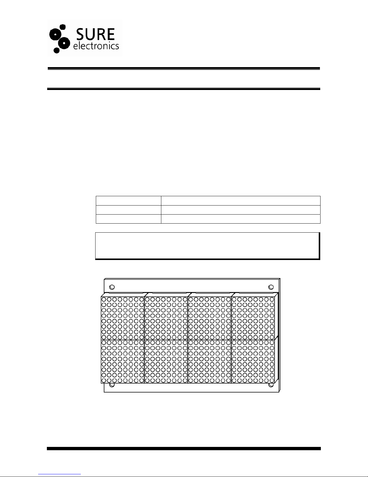
Thanks for using 3216 bicolor LED dot matrix info board series by Sure Electronics.
Integrating four HT1632Cs as driver chips on each info board, these info boards support
16-level PWM brightness control and all LED dot matrixes displayed are mapped to the
RAM of HT1632Cs. Peripheral circuits are required to light up LEDs via the ports on the
boards, providing red, green and even yellow display when red and green LEDs are
illuminated simultaneously. These info boards can be used to display digits, letters and
even graphs. It is recommended to connect up to 2 boards of the same kind in series for
wider applications such as info display in banks, stores, households and so on. You may
refer to the following table for members of this series.
TABLE 1-1 3216 BICOLOR LED DOT MATRIX DISPLAY INFO BOARD SERIES
Product Number Product Name
DE-DP14112 3216 Bicolor LED 3mm Dot Matrix Display Information Board
DE-DP14211 3216 Bicolor LED 5mm Dot Matrix Display Information Board
Note: 4 info boards connected in series are available when the boards are powered by
5V, 2A supply. If the power supply you used can output more power and the info boards
are only used to display common ASCII, more boards can be connected in series.
However, we assume no liability for any damage or risk caused by this.
FIGURE 1-1 FRONT VIEW OF 3216 LED 3MM DOT MATRIX DISPLAY INFO BOARD
DE-DP14112&DE-DP14211_Ver1.1_Page 1
Page 5
3216 Bicolor LED 3mm (5mm) Dot Matrix Display Information Board
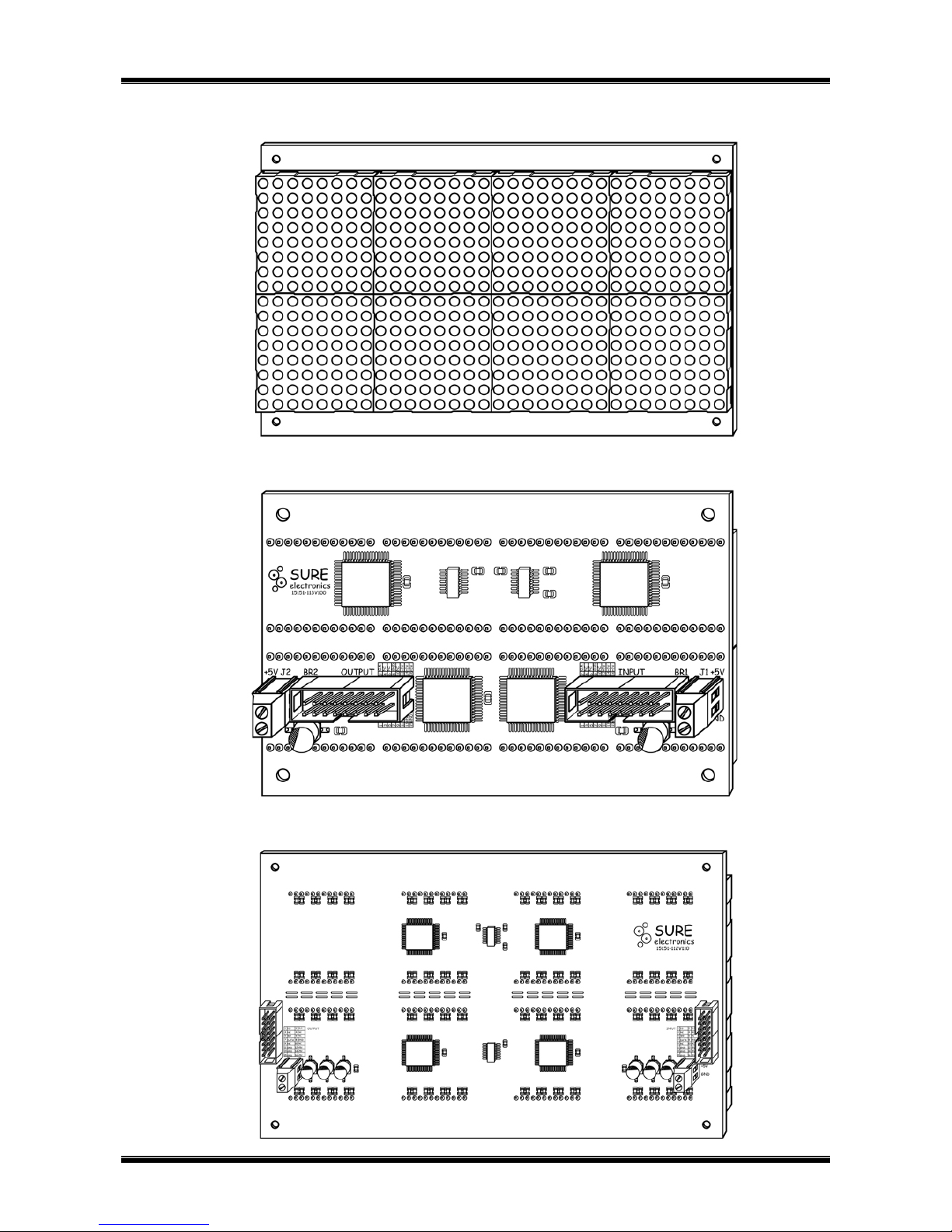
FIGURE 1-2 FRONT VIEW OF 3216 LED 5MM DOT MATRIX DISPLAY INFO BOARD
FIGURE 1-3 BACK VIEW OF 3216 LED 3MM DOT MATRIX DISPLAY INFO BOARD
FIGURE 1-4 BACK VIEW OF 3216 LED 5MM DOT MATRIX DISPLAY INFO BOARD
2004-2009 Sure Electronics Inc
DE-DP14112&DE-DP14211_Ver1.1_Page 2
Page 6
Overview
1.2 Quick Start
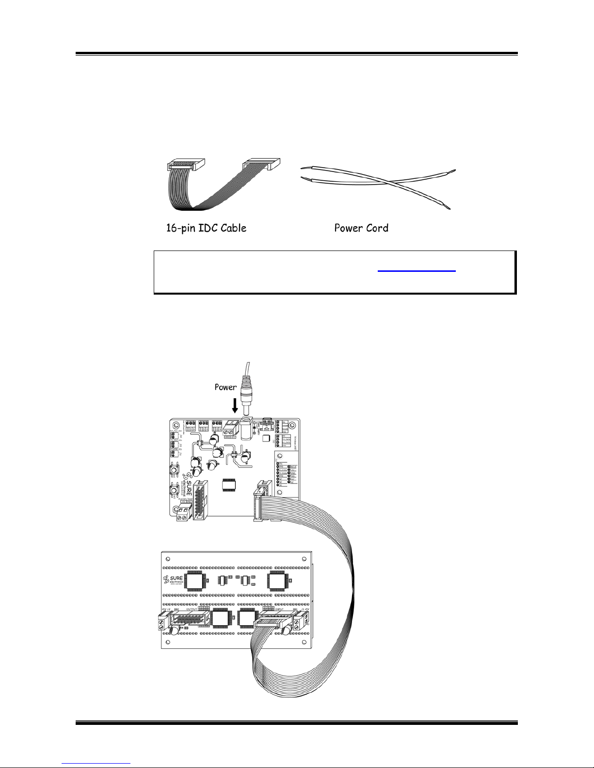
A 16-p in IDC cable and two pow er cords are provided for free. DE-DD210 by Sure
Electronics is used in this manual as a driver board. Program this driver board to control
the display on the info board.
FIGURE 1-5 ACCESSARIES
Note:
1. Other driver board can be used. You may refer to
2.2 Port Definition to do relative
adjustments.
2. Sample codes are provided in this manual for reference.
1.2.1 Connection of One Info Board and The Driver Board
Connect BR1 of the info board and BR1 of the driver board with a 16-pin IDC cable.
FIGURE 1-6 CONNECTION OF THE DRIVER BOARD AND ONE INFO BOARD
2004-2009 Sure Electronics Inc.
DE-DP14112&DE-DP14211_Ver1.1_Page 3
Page 7

3216 Bicolor LED 3mm (5mm) Dot Matrix Display Information Board
Program codes to the chip of the driver board and repower the board.
Note: If you’re not familiar with programming, try using the sample codes first.
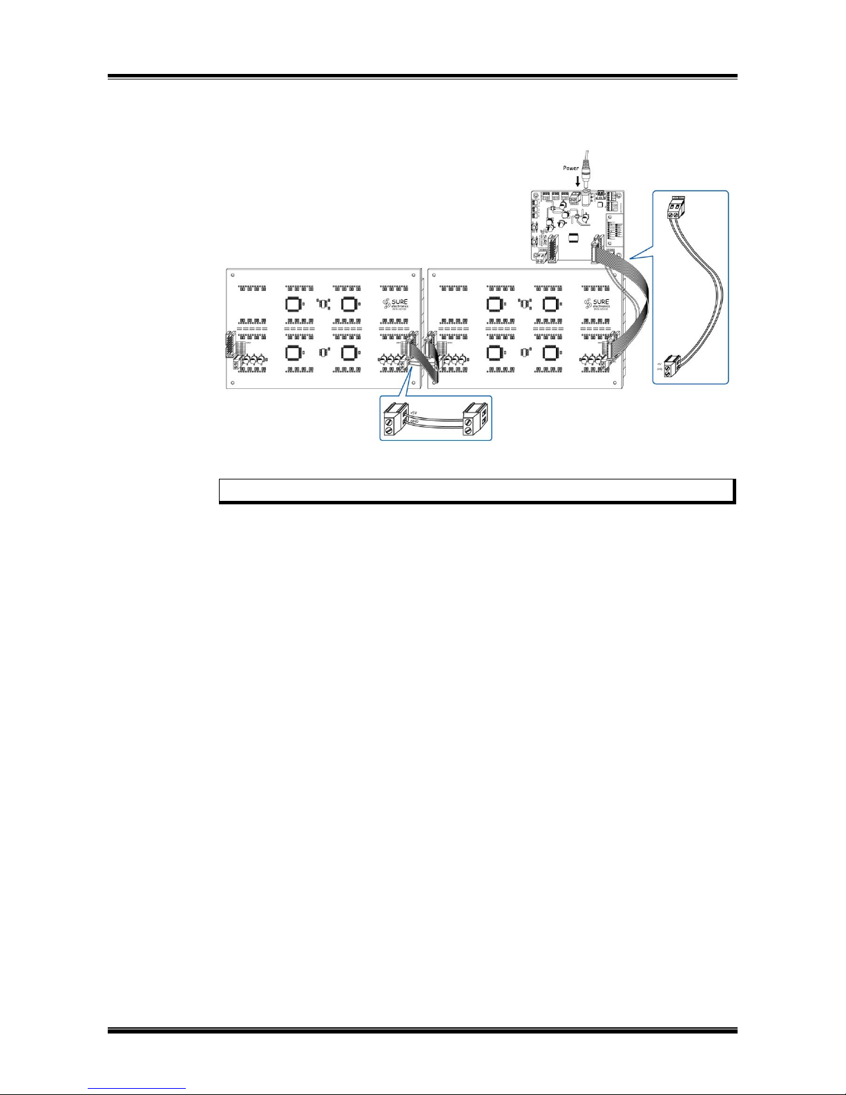
1.2.2 Connection of Many Info Boards
First, auxiliary power cords are recommended to be used when more info boards
connected in series. Connect +5V, GND of terminal J2 on one info board and the
corresponding +5V, GND of terminal J1 on the next info board with auxiliary power cords.
The auxiliary supply should be able to output DC5V 4A. Up to two info boards are
recommended to be connected in series.
Connect BR1 of the driver board and BR1 of the info board with a 16-pin IDC cable.
Then, as shown in figure 1-7, connect two 3216 info boards and the driver board with
two16-pin IDC cables and power cords.
FIGURE 1-7 CONNECTION OF TWO 3216 BICOLOR 3MM LED DOT MATRIX
DISPLAY INFO BOARDS IN SERIES
2004-2009 Sure Electronics Inc
DE-DP14112&DE-DP14211_Ver1.1_Page 4
Page 8
Overview
FIGURE 1-8 CONNECTION OF TWO 3216 BICOLOR 5MM LED DOT MATRIX
DISPLAY INFO BOARDS IN SERIES
Program the chip on the driver board to control the LED display.
Note: If you use the sample codes, all the boards will display the same content.
2004-2009 Sure Electronics Inc.
DE-DP14112&DE-DP14211_Ver1.1_Page 5
Page 9
3216 BICOLOR LED 3MM
(5MM) DOT MATRIX DISPLAY
INFORMATION BOARD
USER’S GUIDE
2004-2009 Sure Electronics Inc.
Chapter 2. Hardware Detail
2.1 Hardware
1. 8 pieces of 8*8 bicolor LED dot matrix
Light-emitting diameter of DE-DP14112 is 3mm. Light-emitting diameter of
DE-DP14211 is 5mm.
2. LED drive chip (U2, U3, U5, and U6): four HT1632C chips, QFP packaging.
3. 16-pin male sockets (BR1 and BR2): used for data, clock, control signal and +5V
supply input.
4. Auxiliary power supply terminal (+5V) (J1and J2): for external power input when
more info boards are connected in series.
2.2 Port Definition
TABLE 2-1 PIN DEFINITION OF BR1
Pin Number Pin Name Function Description
8, 11, 13, 15 GND GND
12, 14, 16 VCC Power Supply
3, 4, 6, 9, 10 NC No Connection
1 CS Chip Select signal input
2 CLK Chip Select clock signal input
5 WR WRITE data clock input
7 DATA Data Input
TABLE 2-2 PIN DEFINITION OF BR2
Pin Number Pin Name Function Description
8, 11, 13, 15 GND GND
12, 14, 16 VCC Power Supply
3, 4, 6, 9, 10 NC No Connection
1 CS Chip Select signal output
2 CLK Chip Select clock signal input
5 WR WRITE data clock output
7 DATA Data Output
DE-DP14112&DE-DP14211_Ver1.1_Page 6
Page 10

3216 Bicolor LED 3mm (5mm) Dot Matrix Display Information Board
2004-2009 Sure Electronics Inc.
DE-DP14112&DE-DP14211_Ver1.1_Page 7
2.3 Display Memory
Display is controlled by modifying the data stored in RAM of HT1632Cs. Every two 8*8
dot matrix displays on the board are controlled by one HT1632C, as shown in the
following figure 2-2. The first half of HT1632C’s addresses control the circuits of green
LEDs and the rest addresses control circuits of red LEDs.
The distribution of HT1632Cs’ corresponding address is shown as follows:
TABLE 2-3 THE CORRESPONDING ADDRESS OF ONE HT1632C
Com7 Com6 Com5 Com4 Addr Com3 Com2 Com1 Com0 Addr
Out0 01H 00H
Out1 03H 02H
Out2 05H 04H
Out3 07H 06H
Out4 09H 08H
Out5 0BH 0AH
Out6 0DH 0CH
Out7
The rest green LEDs of the first
matrix
0FH
The upper half green LEDs of
the first matrix
0EH
Out8 11H 10H
Out9 13H 12H
Out10 15H 14H
Out11 17H 16H
Out12 19H 18H
Out13 1BH 1AH
Out14 1DH 1CH
Out15
The rest green LEDs of the
second matrix
1FH
The upper half green LEDs of
the second matrix
1EH
Out16 21H 20H
Out17 23H 22H
Out18 25H 24H
Out19 27H 26H
Out20 29H 28H
Out21 2BH 2AH
Out22 2DH 2CH
Out23
The rest red LEDs of the first
matrix
2FH
The upper half red LEDs of the
first matrix
2EH
Out24 31H 30H
Out25 33H 32H
Out26 35H 34H
Out27 37H 36H
Out28 39H 38H
Out29 3BH 3AH
Out30 3DH 3CH
Out31
The rest red LEDs of the
second matrix
3FH
The upper half red LEDs of the
second matrix
3EH
Page 11

Hardware Detail
FIGURE 2-1 THE CORRESPONDING ADDRESS OF ONE HT1632C
FIGURE 2-2 DISTRIBUTION OF FOUR HT1632CS
2.4 Command Format
CS (CS1CS2CS3CS4) of HT1632C must be set to low before data or command is
sent to this HT1632C. When the transmission is complete, CS must be reset to high.
Enabling U2 (HT1632C) to individually send data to some address space is taken as an
example. The timing diagram is shown as follows:
2004-2009 Sure Electronics Inc
DE-DP14112&DE-DP14211_Ver1.1_Page 8
Page 12

3216 Bicolor LED 3mm (5mm) Dot Matrix Display Information Board
FIGURE 2-3 TIMING DIAGRAM
CS_BR1
CLK_BR1
QA_74164
QB_74164
QC_74164
QD_74164
DATA
0 0
A6A0
D0D3
Command
2004-2009 Sure Electronics Inc.
DE-DP14112&DE-DP14211_Ver1.1_Page 9
Note: You m ay r ef er to H T1 632C d at a sh eet f or d etai ls .
2.5 Command Summary
Command summary is shown in the following table. For this info board, these
commands - WRITE, SYS EN, LED On, LED Off, RC Master Mode, COM Option and
PWM Duty are recommended to be used. Using the commands which are not
recommended may cause abnormal display.
0 0
C8C0
command_1
C8C0
command_n
Page 13

Hardware Detail
FIGURE 2-4 COMMAND SUMMARY
2004-2009 Sure Electronics Inc
DE-DP14112&DE-DP14211_Ver1.1_Page 10
Page 14

3216 BICOLOR LED 3MM
(5MM) DOT MATRIX DISPLAY
INFORMATION BOARD
USER’S GUIDE
2004-2009 Sure Electronics Inc.
TABLE 3-1 ELECTRICAL CHARACTERISTICS
Parameter
Chapter 3. Electrical Characteristics
Symbol Value Unit
Operating Voltage V
in
5 V
Storage Temperature T
stg
-20 to 80
Average Operating Current I
avrg
0.5 A
Maximum Operating Current
(All LEDs on, 100% PWM duty cycle)
1.37 A
I
max
DE-DP14112&DE-DP14211_Ver1.1_Page 11
Page 15

3216 BICOLOR LED 3MM
(5MM) DOT MATRIX DISPLAY
INFORMATION BOARD
USER’S GUIDE
2004-2009 Sure Electronics Inc.
Chapter 4. Mechanical Drawing
FIGURE 4-1 MECHANICAL DRAWING OF ONE 3216 BICOLOR LED 3MM DOT
MATRIX DISPLAY INFO BOARD
Symbol L1 L2 L3 L4 L5 R
inch 5.05 4.65 3.20 2.80 2.54 0.06
mm 128.27 118.11 81.3 71. 1 64.4 1.50
DE-DP14112&DE-DP14211_Ver1.1_Page 12
Page 16

3216 Bicolor LED 3mm (5mm) Dot Matrix Display Information Board
FIGURE 4-2 MECHANICAL DRAWING OF ONE 3216 BICOLOR LED 5MM DOT
MATRIX DISPLAY INFO BOARD
Symbol L1 L2 L3 L4 L5 R
inch 9.50 8.90 5.80 5.20 4.74 0.06
mm 241.30 226.06 147.32 132.08 120.40 1.50
2004-2009 Sure Electronics Inc.
DE-DP14112&DE-DP14211_Ver1.1_Page 13
Page 17

3216 BICOLOR LED 3MM
(5MM) DOT MATRIX DISPLAY
INFORMATION BOARD
USER’S GUIDE
2004-2009 Sure Electronics Inc.
DE-DP14112&DE-DP14211_Ver1.1_Page 14
5.1 Schematic
FIGURE 5-1 SCHEMATIC
Cathode_1_7
Cathoed_4_0
Anode_1_5
R23 33R
33R
Cathode_2_8
Cathode_1_16
Cathode_2_23
Cathode_2_0
Anode_4_4
R115
33R
R6 33R
Cathode_1_8
R76
Cathoed_4_16
33R
R3333R
33R
R28 33R
U6
HT1632C/QFP -52
14
19
202324
1516171821
22
434249
48254644454740
3538343332
31
568
9
7
101112
30
39
37
123414
26
271329
28
505152
36
VSS
CS
SYNC
COM1
COM2
OSC
DATA
WR
RD
VDD
COM0
ROW21
ROW22
ROW15
ROW16
LED_VSS_1
ROW18
ROW20
ROW19
ROW17
ROW24/COM15
ROW27/COM12
LED_VDD_2
ROW28/COM11
ROW29/COM10
ROW30/COM9
ROW31/COM8
ROW7
ROW6
ROW5
ROW4
LED_VDD_1
ROW3
ROW2
ROW1
COM7
ROW25/COM14
ROW26/COM13
ROW11
ROW10
ROW9
ROW23
ROW8
COM3
COM4
ROW0
COM6
COM5
ROW14
ROW13
ROW12
LED_VSS_2
R4833R
Cathode_1_12
Cathode_2_17
Cathode_3_25
Cathode_3_13
33R
C8
104
1 2
Cathode_2_9
R86
Cathode_3_10
R5133R
R4433R
Cathode_2_28
Anode_2_6
Cathoed_4_31
R99
33R
R5033R
Cathode_2_18
Cathode_2_31
Anode_3_1
R122
Cathode_2_16
R4 33R
R3833R
D1
LED
221916
13
369
12
23
20
17
14
2
5
8
11
10741151821
24
Cathode_2_14
Cathode_2_8
Anode_3_3
Anode_1_3
CLK_IN
33R
Cathode_3_24
33R
Anode_3_5
Cathoed_4_29
Cathoed_4_1
Anode_4_7
U5
HT1632C/QFP-52
14
19
202324
1516171821
22
434249
48254644454740
3538343332
31
568
9
7
101112
30
39
37
123414
26
271329
28
505152
36
VSS
CS
SYNC
COM1
COM2
OSC
DATA
WR
RD
VDD
COM0
ROW21
ROW22
ROW15
ROW16
LED_VSS_1
ROW18
ROW20
ROW19
ROW17
ROW24/COM15
ROW27/COM12
LED_VDD_2
ROW28/COM11
ROW29/COM10
ROW30/COM9
ROW31/COM8
ROW7
ROW6
ROW5
ROW4
LED_VDD_1
ROW3
ROW2
ROW1
COM7
ROW25/COM14
ROW26/COM13
ROW11
ROW10
ROW9
ROW23
ROW8
COM3
COM4
ROW0
COM6
COM5
ROW14
ROW13
ROW12
LED_VSS_2
+5V
Anode_2_5
Anode_2_4
R74
Anode_3_7
R17 33R
R25 33R
Cathode_1_0
Cathode_2_13
Anode_4_5
Anode_4_3
GND
Anode_1_5
33R
33R
Cathode_2_19
CS2
Cathoed_4_27
Anode_3_5
Cathoed_4_22
33R
R109
Anode_3_[0..7]
GND
R10 33R
33R
Cathode_2_1
Cathoed_4_21
Cathode_3_26
U4B
74HCT04D/SO
3 4
147
+5V
Cathode_2_26
R120
Cathoed_4_9
R5733R
D8
LED
221916
13
369
12
23
20
17
14
2
5
8
11
10741151821
24
R4533R
Anode_2_[0..7]
Cathode_1_5
Anode_4_2
Cathode_3_15
33R
Cathode_1_28
DATA_OUT
Cathode_3_21
CS_IN
33R
+5V
R90
Cathode_3_[0..31]
33R
R105
DATA_OUT
D6
LED
221916
13
369
12
23
20
17
14
2
5
8
11
10741151821
24
Cathode_1_15
Cathode_1_28
Cathode_2_3
Cathode_2_25
Anode_4_0
Cathode_3_27
Cathode_1_10
R128
WR_OUT
R123
R88 Cathoed_4_13
Cathode_3_2
33R
+5V
Cathode_1_11
R87
Anode_3_4
DATA_OUT
Cathoed_4_24
R108
Cathode_3_26
Cathode_2_16
Anode_4_5
R75
R3933R
33R
Anode_3_7
Cathoed_4_14
Anode_1_6
Cathode_1_0
R65
Cathoed_4_23
U4C
74HCT04D/SO
5 6
147
R19 33R
Cathode_3_11
33R
D3
LED
221916
13
369
12
23
20
17
14
2
5
8
11
10741151821
24
C6
104
12
+5V
Anode_2_4
Cathode_2_10
Anode_3_4
Anode_4_1
Cathode_2_1
Cathode_2_11
Cathoed_4_27
Cathoed_4_5
Anode_1_4
Cathode_3_14
Cathode_3_31
R27 33R
33R
D5
LED
221916
13
369
12
23
20
17
14
2
5
8
11
10741151821
24
Cathode_2_15
Cathoed_4_1
+
C9
10V 100uF
12
R6033R
33R
Cathode_1_4
Cathode_2_6
R113
GND
33R
U2
HT1632C/QFP -52
14
19
202324
1516171821
22
434249
48254644454740
3538343332
31
568
9
7
101112
30
39
37
123414
26
271329
28
505152
36
VSS
CS
SYNC
COM1
COM2
OSC
DATA
WR
RD
VDD
COM0
ROW21
ROW22
ROW15
ROW16
LED_VSS_1
ROW18
ROW20
ROW19
ROW17
ROW24/COM15
ROW27/COM12
LED_VDD_2
ROW28/COM11
ROW29/COM10
ROW30/COM9
ROW31/COM8
ROW7
ROW6
ROW5
ROW4
LED_VDD_1
ROW3
ROW2
ROW1
COM7
ROW25/COM14
ROW26/COM13
ROW11
ROW10
ROW9
ROW23
ROW8
COM3
COM4
ROW0
COM6
COM5
ROW14
ROW13
ROW12
LED_VSS_2
Anode_2_6
R69
R68
Cathode_3_22
Anode_1_1
D7
LED
221916
13
369
12
23
20
17
14
2
5
8
11
10741151821
24
Cathode_1_20
Anode_2_1
R72
Cathode_1_9
Anode_4_2
CS4
Cathode_3_28
R15 33R
33R
Anode_2_3
Anode_4_4
Anode_4_6
R89
R118
R70
R1 33R
Cathode_1_2
Anode_3_6
R82
Anode_3_0
Anode_1_7
Cathode_3_16
Cathode_3_4
33R
33R
Cathode_1_1
R85
Cathoed_4_26
Cathode_1_19
Cathode_1_7
R31 33R
Cathode_1_3
WR_OUT
CS_IN
GND
R20 33R
R14 33R
Anode_2_0
Anode_2_3
Anode_3_0
CS4
Cathode_3_30
33R
R4333R
CS1
Anode_2_5
Cathoed_4_6
Cathoed_4_13
R18 33R
1
101214
16
3579111315
246
8
BR2
MSV8X2
Anode_2_1
Cathode_1_23
Cathode_2_21
Anode_3_6
Cathoed_4_11
33R
R5333R
R21 33R
+5V
Cathode_2_6
Cathoed_4_31
Anode_4_6
Cathoed_4_15
Cathoed_4_14
Anode_1_7
Cathode_3_29
DATA_OUT
C12
104
12
Cathode_1_19
Cathode_1_14
Cathode_1_24
Cathode_2_17
Cathode_2_23
Anode_4_1
R92
Cathode_3_9
33R
Anode_4_0
R71
Anode_4_0
R3633R
Cathoed_4_26
R112
CS3
C2
10pF
12
R7 33R
R5233R
Cathode_1_21
Cathode_2_12
Cathode_2_4
Cathoed_4_7
Cathode_3_12
+
C10
10V 100uF
12
R6333R
Cathode_1_12
Anode_4_7
Cathode_3_30
Anode_1_0
Cathoed_4_17
Cathoed_4_0
Cathoed_4_25
Cathode_3_8
33R
R29 33R
33R
Anode_1_[0..7]
R121
R80
Cathoed_4_4R83
Cathoed_4_28
Cathode_1_1
Cathode_2_7
Cathode_1_25
Cathode_2_5
Cathode_3_23
CLK_OUT
GND
R4133R
Cathode_2_30
Cathode_1_[0..31]
Cathoed_4_21
Cathode_3_0
R5 33R
Cathode_3_23
Cathode_3_10
33R
Anode_2_0
Cathoed_4_30
Cathoed_4_18
Anode_3_1
Anode_4_4
WR_OUT
Anode_3_2
R124
Cathoed_4_9
CS_OUT
1
2
J1
MSV2
33R
R13 33R
R98
R77
Cathoed_4_3
Cathoed_4_12
Anode_1_7
Anode_1_6
Cathode_3_5
Cathode_3_20
R26 33R
R12 33R
Anode_2_7
R114
Cathoed_4_7
R103
R84
Cathode_3_29
Cathode_1_20
Cathode_3_1
33R
R24 33R
Cathode_1_31
Cathoed_4_22
Cathoed_4_3
Cathode_3_14
Cathode_3_13
33R
Cathode_1_10
Cathode_1_15
Cathode_2_5
Cathode_2_3
Anode_4_2
Anode_1_2
WR_IN
33R
33R
R3433R
+5V
R81
R73
Cathoed_4_15
Cathode_3_6
33R
Cathode_2_22
Cathode_2_25
Cathode_1_6
R126
Cathoed_4_17
Cathoed_4_8
33R
Cathode_2_19
Anode_4_6
Cathode_3_8
33R
33R
+5V
Cathode_2_9
Anode_1_1
33R
R22 33R
R102
33R
R5533R
Cathode_1_29
Cathoed_4_19
R104
R117
Cathode_3_7
Cathode_3_2
Cathode_3_19
GND
R110
Cathode_3_20
Anode_1_2
33R
Cathode_1_6
Cathode_4_[0..31]
DATA_IN
Cathode_3_7
33R
R16 33R
Anode_2_2
Anode_4_[0..7]
Cathode_3_24
R3533R
C7
104
1 2
33R
1
2
J2
MSV2
33R
Cathode_3_1
Anode_2_6
Cathode_1_13
Cathode_1_18
Cathode_1_21
Cathode_1_26
Anode_2_4
33R
33R
C4
104
1 2
Cathode_2_21
Cathode_2_22
Cathode_2_26
R66
Cathoed_4_20
C5
104
12
U3
HT1632C/QFP -52
14
19
202324
1516171821
22
434249
48254644454740
3538343332
31
568
9
7
101112
30
39
37
123414
26
271329
28
505152
36
VSS
CS
SYNC
COM1
COM2
OSC
DATA
WR
RD
VDD
COM0
ROW21
ROW22
ROW15
ROW16
LED_VSS_1
ROW18
ROW20
ROW19
ROW17
ROW24/COM15
ROW27/COM12
LED_VDD_2
ROW28/COM11
ROW29/COM10
ROW30/COM9
ROW31/COM8
ROW7
ROW6
ROW5
ROW4
LED_VDD_1
ROW3
ROW2
ROW1
COM7
ROW25/COM14
ROW26/COM13
ROW11
ROW10
ROW9
ROW23
ROW8
COM3
COM4
ROW0
COM6
COM5
ROW14
ROW13
ROW12
LED_VSS_2
Cathode_1_24
Cathode_1_18
Cathode_1_14
R91
Cathode_3_25
GND
Cathode_1_4
Cathode_2_[0..31]
WR_OUT
CLK_IN
R32 33R
R4733R
Anode_2_0
R97
CS1
GND
33R
R4933R
Anode_2_7
Cathode_1_13
Cathode_1_22
Cathode_2_31
Cathoed_4_10
Anode_1_6
Anode_1_3
33R
R11 33R
Anode_2_2
Anode_2_1
Cathode_2_4
R127
Cathoed_4_2
R100
U4A
74HCT04D/SO
1 2
147
Anode_3_2 Cathoed_4_8
Anode_1_3
Cathode_3_17
U4D
74HCT04D/SO
9 8
147
R5433R
Cathode_2_27
Cathode_2_11
R95
R101
DATA_OUT
Cathoed_4_10
CS_OUT
Cathode_3_6
Cathode_1_9
Cathode_1_3
Cathode_2_2
Anode_4_3
Cathoed_4_6
Cathode_3_15
33R
33R
Cathode_1_5
Anode_3_5
Anode_3_6
Cathoed_4_2
Cathode_3_17
Cathode_3_18
DATA_IN
33R
+5V
Cathoed_4_16
Cathode_3_31
33R
Cathode_3_19
Cathode_3_3
33R
C1
10pF
12
Anode_3_2
Anode_1_1
WR_IN
R8 33R
33R
U4E
74HCT04D/SO
11 10
147
R125
R67
R111
R106
+5V
Cathode_1_16
Cathode_2_20
Anode_3_0
Cathode_3_18
Anode_1_5
R6233R
Cathode_1_30
Cathode_2_7
R107
Cathoed_4_24
Cathoed_4_30
Cathoed_4_12
R4233R
D2
LED
221916
13
369
12
23
20
17
14
2
5
8
11
10741151821
24
Cathode_2_20
Cathode_2_28
Cathode_3_27
WR_OUT
33R
Cathode_1_25
R78
Anode_3_3
Anode_1_4
Cathode_3_28
R5933R
33R
Anode_2_5
Cathode_2_15
Cathode_2_29
Cathoed_4_25
Cathode_3_9
Anode_4_5
Cathode_1_8
Cathode_1_2
Cathode_1_22
Cathoed_4_5
Cathoed_4_19
Anode_3_4
Anode_1_4
Cathode_3_22
Cathode_3_16
CLK_OUT
R6133R
33R
Cathode_2_24
Cathode_1_27
R96
Cathoed_4_20
CLK_OUT
R5833R
R30 33R
R5633R
Cathode_1_29
Cathode_2_24
WR_OUT
R4033R
Cathode_1_11
Cathode_1_27
Cathode_2_29
33R
R4633R
Anode_4_3
R116
R79
33R
1
101214
16
3579111315
246
8
BR1
MSV8X2
Anode_2_2
Cathode_1_31
Cathode_2_18
Cathode_2_27
R94
CS2
Anode_1_0
Cathode_3_5
Cathode_1_23
CS3
Cathoed_4_23
R9 33R
Cathoed_4_4
Cathoed_4_11
Cathoed_4_18
33R
C3
104
12
R6433R
R3733R
Anode_2_3
Cathode_2_0
Anode_3_1
DATA_OUT
U1
74HC164
789
14
3456101112
13
1
2
GND
CLK
CLR
VCC
QA
QB
QC
QD
QE
QF
QG
QH
A
B
R119
Cathode_3_0
Cathode_2_12
Anode_4_1
Cathode_3_21
Anode_1_2
Anode_1_0
Cathode_3_4
Cathode_3_11
Cathode_3_3
Cathoed_4_28
R3 33R
Anode_2_7
Anode_3_7
Cathoed_4_29
GND
33R
U4F
74HCT04D/SO
13 12
147
D4
LED
221916
13
369
12
23
20
17
14
2
5
8
11
10741151821
24
33R
Cathode_1_26
Cathode_1_17
Cathode_1_30
Cathode_1_17
Cathode_2_14
Cathode_2_30
Anode_4_7
Anode_3_3
C11
104
12
Cathode_2_10Cathode_2_2
Cathode_2_13
R93
Cathode_3_12
R2 33R
33R
Chapter 5. Appendix
Page 18

3216 Bicolor LED 3mm (5mm) Dot Matrix Display Information Board
2004-2009 Sure Electronics Inc.
DE-DP14112&DE-DP14211_Ver1.1_Page 15
5.2 Sample Code
The driver board DE-DD210, integrating PIC16F723 as its master chip, is used as an
example. This sample code is used to illuminate the odd rows of LEDs in green.
Compilation environment: MPLAB IDE v8.40
Compiler: HI-TECH ANSI C Compiler PRO 9.65
File “Declare.h”
#ifndef _DECLARE_
#define _DECLARE_
//Macro definition of ports used
#define A_74164 RB1
#define CLK_74164 RB2
#define CLK RC3 //Clock line simulating SPI communication (this
//port is also the clock line of SPI communication
//integrated by MCU)
#define DAT RC5 //Data line simulating SPI communication (this
//port is also the data line of SPI communication
//integrated by MCU)
//Following is the functions defined in a way of macro definition.
#define CLK_DELAY NOP()
//Following definition facilitates compilation of HT1632C control commands.
#define SLAVE_MODE 0b100000100000
//[HT1632C]Set slave mode and clock source from external clock
#define RC_MASTER_MODE 0b100000110000
//[HT1632C]Set master mode and clock source from on-chip RC oscillator
#define EXT_CLK_MASTER_MODE 0b100000111000
//[HT1632C]Set master mode and clock source from external clock
#define SYS_EN 0b100000000010 //Turn on system oscillator
#define LED_ON 0b100000000110 //Turn on LED duty cycle generator
#define N_MOS_COM8 0b100001000000
//N-MOS open drain output and 8 common option
#define PWM_10 0b100101010010 //PWM 10/16 duty
#endif
Page 19

Appendix
2004-2009 Sure Electronics Inc
DE-DP14112&DE-DP14211_Ver1.1_Page 16
File “SampleCode.c”
#include <pic.h>
#include "Declare.h"
//**************************************************************************************************
//Function Name: device file configuration
//Function Feature: configure MCU’s working modes and status
//Input Argument: INTIO: INTOSCIO- internal oscillator, OSC1 and OSC2 used as I/O
//ports
//WDTDIS: disable watchdog timer
//PWRTDIS: disable power-delay timer
//MCLREN: enable MCLR
//UNPROTECT: do NOT protect the code
//BORDIS: brown out reset disable
//BORV25: brown-out reset voltage set to 2.5V nominal
//PLLEN:
//DEBUGEN: in-circuit debugger enabled
//
//VCAPDIS: voltage regulator capacitor disabled
// Output Argument: void
//**************************************************************************************************
__CONFIG(INTIO & WDTDIS & PWRTEN & MCLREN & UNPROTECT & BORDIS &
BORV25 & PLLEN & DEBUGEN);
__CONFIG(VCAPDIS);
//Constant Definition
#define CHIP_MAX 4 //Four HT1632Cs on one board
//Function Prototype Declaration
void SystemInit(void); //System Initialization
void SetHT1632C_As3208(void); //Set HT1632Cs work on mode 32*8
void OutputCLK_Pulse(void); //CLK pin outputs a clock pulse
void OutputA_74164(unsigned char x); //CS pin output a level
void ChipSelect(int select); //Chip selection
void CommandWriteHT1632C(unsigned int command); //Write command to ALL
//HT1632Cs
void AddressWriteHT1632C(unsigned char address);//Write Address to HT1632Cs
void SPI_ModelConfigure(void);
void SPI_DataSend(const unsigned char data);
void main()
{
unsigned char i, j;
SystemInit(); //System Initialization
SetHT1632C_As3208(); //Set all HT1632Cs to work in 32*8 master mode
Page 20

3216 Bicolor LED 3mm (5mm) Dot Matrix Display Information Board
2004-2009 Sure Electronics Inc.
DE-DP14112&DE-DP14211_Ver1.1_Page 17
for(i=1; i<=CHIP_MAX; i++)
{
ChipSelect(i); //Chip select the corresponding HT1632C
AddressWriteHT1632C(0x00); //Get the selected start address of the chip
SPI_ModelConfigure(); //Open SPI mode, continuously send data to
HT1632C
for(j=0; j<32; j++) //Take “0x00” as the start address, continuously
write data
{
SPI_DataSend(0xaa); //Write data as 0xaa
}
SSPCON = 0x11; //Close SPI mode
}
while(1);
}
//**************************************************************************************************
//Function Name: system initialization
//Function Feature: set corresponding data reading and writing of PORTB and PORTC
//Input Argument: void
//Output Argument: void
//**************************************************************************************************
void SystemInit(void)
{
IRCF1 = 1;
IRCF0 = 0; //Set the frequency of the internal oscillator as 8MHz
OSCTUNE = 0x1f; //Oscillator at the maximum frequency
ANSELB = 0x00; //PORTB as a digital I/O port
TRISB = 0x00; //PORTB as an output port
PORTB = 0x00; //Clear PORTB output (PORTB’s status is uncertain after
power-on reset)
TRISC0 = 1; //PORTC0 (SW1 port) as an input port
TRISC1 = 1; //PORTC1 (SW2 port) as an input port
TRISC3 = 0; //PORTC3 (CLK signal) as an output port
TRISC5 = 0; //PORTC5 (DATA signal) as an output port
T0IE = 0; //Turn off interruption of timer0
}
//**************************************************************************************************
//Function Name: SetHT1632C_As3208
//Function Feature: write basic configuration to HT1632C in command words
//Input Argument: void
//Output Argument: void
//**************************************************************************************************
void SetHT1632C_As3208(void)
Page 21

Appendix
2004-2009 Sure Electronics Inc
DE-DP14112&DE-DP14211_Ver1.1_Page 18
{
CommandWriteHT1632C(SYS_EN); //Enable system oscillator
CommandWriteHT1632C(LED_ON); //Turn on LED
CommandWriteHT1632C(RC_MASTER_MODE); //Select on-chip RC as the
clock’s master mode. Select this sentence when HT1632C is changed.
CommandWriteHT1632C(N_MOS_COM8); //N-MOS open-drain output
//and 32 ROW * 8 COM
CommandWriteHT1632C(PWM_10); //PWM 10/16 duty
}
//**************************************************************************************************
//Function Name: OutputCLK_Pulse
//Function Feature: enable CLK_74164 pin to output a clock pulse
//Input Argument: void
//Output Argument: void
//**************************************************************************************************
void OutputCLK_Pulse(void) //Output a clock pulse
{
CLK_74164 = 1;
CLK_DELAY;
CLK_74164 = 0;
CLK_DELAY;
}
//**************************************************************************************************
//Function Name: OutputA_74164
//Function Feature: enable pin A of 74164 to output 0 or 1
//Input Argument: x: if x=1, 74164 outputs high. If x1, 74164 outputs low.
//Output Argument: void
//**************************************************************************************************
void OutputA_74164(unsigned char x) //Input a digital level to 74164
{
if(x==1)
{
A_74164 = 1;
CLK_DELAY;
}
else
{
A_74164 = 0;
CLK_DELAY;
}
}
Page 22

3216 Bicolor LED 3mm (5mm) Dot Matrix Display Information Board
2004-2009 Sure Electronics Inc.
DE-DP14112&DE-DP14211_Ver1.1_Page 19
//**************************************************************************************************
//Function Name: CommandWriteHT1632C
//Function Feature: Write control commands to all HT1632Cs
//Input Argument: command words written to “command”, specifically stated in “declare”
//function
//Output Argument: void
//Argument Description: compile control commands to all external HT1632Cs for the
//requirement of the project
//**************************************************************************************************
void CommandWriteHT1632C(unsigned int command)
{
unsigned char i;
unsigned int j;
command = command & 0x0fff; //12-bit command word, mask upper four bits
ChipSelect(0); //Disable all HT1632Cs
CLK_DELAY;
ChipSelect(-1); //Enable all HT1632Cs
CLK_DELAY;
for(i=0; i<12; i++) //Write command words in HI1632C register
{
CLK = 0;
CLK_DELAY;
j = command & 0x0800; //Return the MSB
command = command << 1; //Move the control character to the left one
j = j >> 11; //Position the value at the LSB
DAT = j; //Send the value to the data port
CLK_DELAY;
CLK = 1; //Data transmission (data valid on rising edge)
CLK_DELAY;
}
ChipSelect(0); //Disable all HT1632Cs
}
//**************************************************************************************************
//Function Name: AddressWriteHT1632C
//Function Feature: write start address of data to HT1632Cs
//Input Argument: address: address to be written
//Output Argument: void
//**************************************************************************************************
void AddressWriteHT1632C(unsigned char address)
{
unsigned char i,temp;
SSPCON = 0x11;
address = address & 0x7f; //7-bit address, mask the MSB
Page 23

Appendix
2004-2009 Sure Electronics Inc
DE-DP14112&DE-DP14211_Ver1.1_Page 20
CLK = 0; //Clock line is 0
CLK_DELAY;
DAT = 1; //Send “1” to data port
CLK_DELAY;
CLK = 1; //Data transmission
CLK_DELAY;
CLK = 0;
CLK_DELAY;
DAT = 0; //Send “0” to data port
CLK_DELAY;
CLK = 1; //Data transmission
CLK_DELAY;
CLK = 0;
CLK_DELAY;
DAT = 1; //Send “1” to data port
CLK_DELAY;
CLK = 1; //Data transmission
CLK_DELAY;
for(i=0; i<7; i++) //Write “address” to HT1632C register
{
CLK = 0; //Clock line is 0
CLK_DELAY;
temp = address & 0x40; //Return the MSB
address = address << 1; //Move the control character to the left one
temp = temp >> 6; //Position the value at the LSB
DAT = temp; //Send the value to the data port
CLK_DELAY;
CLK = 1; //Data transmission
CLK_DELAY;
}
}
//**************************************************************************************************
//Function Name: ChipSelect
//Function Feature: enable HT1632C
//Input Argument: select: HT1632C to be selected
// If select=0, select none.
// If s<0, select all.
//Output Argument: void
//**************************************************************************************************
void ChipSelect(int select)
{
unsigned char tmp = 0;
if(select<0) //Enable all HT1632Cs
{
Page 24

3216 Bicolor LED 3mm (5mm) Dot Matrix Display Information Board
2004-2009 Sure Electronics Inc.
DE-DP14112&DE-DP14211_Ver1.1_Page 21
OutputA_74164(0);
CLK_DELAY;
for(tmp=0; tmp<CHIP_MAX; tmp++)
{
OutputCLK_Pulse();
}
}
else if(select==0) //Disable all HT1632Cs
{
OutputA_74164(1);
CLK_DELAY;
for(tmp=0; tmp<CHIP_MAX; tmp++)
{
OutputCLK_Pulse();
}
}
else
{
OutputA_74164(1);
CLK_DELAY;
for(tmp=0; tmp<CHIP_MAX; tmp++)
{
OutputCLK_Pulse();
}
OutputA_74164(0);
CLK_DELAY;
OutputCLK_Pulse();
CLK_DELAY;
OutputA_74164(1);
CLK_DELAY;
tmp = 1;
for( ; tmp<select; tmp++)
{
OutputCLK_Pulse();
}
}
}
//**************************************************************************************************
//Function Name: SPI_ModelConfigure
//Function Feature: configure the corresponding data transfer port of PIC microcontroller
//for SPI communication
//Input Argument: void
//Output Argument: void
//**************************************************************************************************
Page 25

Appendix
void SPI_ModelConfigure(void)
{
SSPIF = 0; //Initial state: waiting to send data
SSPCON = 0x31; //Write in this register: SSPEN=1 (enable serial port); CKP=1
(CLK high in an idle state); CLK is FOSC/16
SSPSTAT = 0x80; //Write in this register: SMP=1(Input data sampled at end of
//data output time); CKE=0(data stable on rising edge of SCK)
}
//**************************************************************************************************
//Function Name: SPI_DataSend
//Function Feature: transmit data in SPI mode of PIC microcontroller
//Input Argument: data: bytes of data to be transmitted
//Output Argument: void
//**************************************************************************************************
void SPI_DataSend(const unsigned char data)
{
SSPBUF = data; //Start sending
while(!SSPIF); //Wait for data being sent
SSPIF = 0; //Clear flag
}
5.3 Heat Dissipation
Following are pictures of heat dissipation gained by Fluke Ti20 Thermal Imager in the
condition of info board working at full load, all LEDs on and 100% PWM duty cycle.
5.3.1 3216 Bicolor LED 3mm Dot Matrix Display Info Board
FIGURE 5-2 HEAT DISTRIBUTION OF THE BACK PANEL
2004-2009 Sure Electronics Inc
DE-DP14112&DE-DP14211_Ver1.1_Page 22
Page 26

3216 Bicolor LED 3mm (5mm) Dot Matrix Display Information Board
FIGURE 5-3 HEAT DISTRIBUTION OF THE FRONT PANEL
Note: The temperature around U2, U3, U5 and U6 is much higher when 3216 bicolor
LED 5mm dot matrix display info board product works at full load. Take care and ensure
good heat dissipation when using this product.
5.3.2 3216 Bicolor LED 5mm Dot Matrix Display Info Board
FIGURE 5-4 HEAT DISTRIBUTION OF HT1632C’S CENTER ON THE BACK PANEL
2004-2009 Sure Electronics Inc.
DE-DP14112&DE-DP14211_Ver1.1_Page 23
Page 27

Appendix
FIGURE 5-5 HEAT DISTRIBUTION OF THE FRONT PANEL
Note: It’s recommended to use these products in a good thermal environment.
2004-2009 Sure Electronics Inc
DE-DP14112&DE-DP14211_Ver1.1_Page 24
Page 28

3216 BICOLOR LED 3MM
(5MM) DOT MATRIX DISPLAY
INFORMATION BOARD
USER’S GUIDE
2004-2009 Sure Electronics Inc.
Chapter 6. Contact Us
Sure Electronics Co., Ltd.
5F, Zone A,
Qinhuai Technology Innovation Center
105-2 DaMing Rd (ZIP:210022)
Nanjing
P.R.China
Tel: +86-13601408832 (For technical questions only)
+86-25-66606340 (English service, from GMT1-10AM)
Fax: +86-25- 66606341-866
Website: www.sure-electronics.com
www.sure-electronics.net
DE-DP14112&DE-DP14211_Ver1.1_Page 25
 Loading...