

Page 1

24-Port 100/10M N-Way
19 Rack-Mount Smart Switch
Users Manual
EP-824DX-CS
www.surecom.com.tw
#471824DXCS00
www.surecom-net.com
Page 2

FCC Statement
This equipment can generate, use and radiate radio frequency energy and, if not
installed and used in accordance with the instructions in this manual, may cause
interference to radio communications. This equipment has been tested and found to
comply with the limits for a Class A computing device pursuant to Part 15 of the FCC
rules, which are designed to provid reasonable protection against radio interference
when operated in a commercial environment. Operation of this equipment in a
residential area is likely to cause interference, in which case the user, at his own
expense, will be required to take whatever measures are necessary to correct the
interference.
CE Declaration of Conformity
This is a Class A product. In a domestic environment product may cause radio
interference in which case the user may be required to take adequate measures.
Trademarks
All other brands and product names may be registered trademarks or trademarks of
their respective holders.
Table of Contents
Chapter 1 Introduction
Performance Hightlights
Key Features
Package Contents
Chapter 2 Hardware
Front Panel
LED Indicators
Rear Panel
Chapter 3 Network Connections
Switch to PC
Switch to Hub
Hub without Uplink (MDI) Port
Switch to Switch (Other Devices)
Chapter 4 Console Management Setup
Getting Started
Console Program
Hyper Terminal Setup
Chapter 5 The Smart Switch Setup
Getting Started
Using the System Configuration Program
Trunk/VLAN Setting Configuration
Port Status
Port Setting Configuration
Factory Default
Save Setting
Appendix A Technical Specifications
Appendix B Cable Requirements
1-1
1-2
1-3
1-3
2-1
2-1
2-2
2-3
3-1
3-1
3-2
3-3
3-4
4-1
4-1
4-1
4-2
5-1
5-1
5-1
5-3
5-4
5-5
5-6
5-6
A-1
B-1
i
Page 3
1-1
List of Figures
ii
1
Figure 2-1 Front Panel
Figure 2-2 LED Indicators
Figure 2-3 Rear Panel
Figure 3-1 PC or Workstation Connection
Figure 3-2 10BASE-T or 100BASE-TX Hub Connection
Figure 3-3 Connecting to a Hub without Uplink Port
Figure 3-4 Switch to Switch Connection
Figure 4-1 PC to the Switch Connection
Figure 4-2 Terminal Program
Figure 4-3 Hypertrm.exe Icon
Figure 4-4 New Connection Screen
Figure 4-5 Selecting a Com Port
Figure 4-6 COM2 Properties Setting
Figure 4-7 Select Properties Item
Figure 4-8 Emulation Setup
Figure 5-1 Main Menu
Figure 5-2 Trunk Setting Screen
Figure 5-3 VLAN Setting Screen
Figure 5-4 Port Status Screen
Figure 5-5 Port Setting Screen
Figure 5-6 Factory Default Screen
Fiber Slide-in Port
The Switch has a fiber slide-in port. With fiber the workgroup distance could be
extended to 2,000 meters and solve the distance limit.
Full/Half-Duplex and Easy Expansion
The Switch supports both full/half-duplex on all ports which are able to provide
200Mbps of bandwidth to the connected devices using auto-negotiation. The
Switch is also expandable by cascading two or more switches together or
connecting any RJ-45 (MDI-X) port on the Switch to any device such as a
workstation or a server.
Store-and-Forward Scheme
The Switch uses store-and forward switching to ensure all error packets will be
filtered and maintain maximum data integrity, even under heavy loading.
1. Introduction
2-1
2-2
2-3
3-1
3-2
3-3
3-4
4-1
4-2
4-2
4-3
4-3
4-4
4-4
4-5
5-1
5-3
5-3
5-4
5-5
5-6
○○○○○○○○○○○○○○○○○○○○○○○○○○○○○○○○○○○○○○○○○○○○
The 24-Port 100/10M N-Way 19 Rack-Mount Smart Switch is the lastest design in
its N-Way Switches series for easy installation and high-performance in an environment where traffic on the network and the number of users increase continuously. What
makes the 24-Port 100/10M N-Way 19 Rack-Mount Smart Switch stand out from
the crowd is its built-in VLAN and Trunk configuration. With VLAN, stations on
different network segments can be grouped into the same LAN segment. The goal
of VLANs is to allow for complete mobility of workstation placement, yet keeping
broadcast traffic to a minimum. When port of a VLAN, the port will only communicate with other ports in the VLAN. This offers a high degree of security within
the network. With Trunk, the backbone bandwidth can be increased to advance the
network performance by easing and smoothing traffic load at peak hours. Small
businesses and corporate branch offices can take full advantage of 100Mbps Fast
Ethernet performance and preserve existing desktop investment with no changes
required to PCs, NICs, cabling, drivers, or PC configurations.
Page 4
Key Features
1-2
1-3
Conform to IEEE 802.3 10BASE-T, IEEE 802.3u 100BASE-TX /FX, and IEEE 802.3x
flow control for full-duplex standards
Support store-and-forward mode switching
Provide non-blocking twenty-four ports full-wire speed access
Back pressure in half-duplex and flow control in full-duplex
Twenty-four 100/10Mbps RJ-45 ports
Full/half-duplex mode operation on all ports
Support one Uplink port / fiber slide-in port for expansion
Auto-negotiation capability
Source address learning and aging function
Provide 2K MAC address and 4Mbits RAM buffer
LEDs to indicate Power, fiber slide-in, link/activity, full-duplex/collision, and
speed status
One 24-Port 100/10M N-Way 19 Rack-Mount Switch
One Power Cord
One Warranty Card
One Pack of Screws
Two Mounting Brackets
This Users Manual
Note: If any item is damaged or missing, please contact your supplier.
Provide one fiber slide-in port for expansion the workgroup distance to 2,000
meters
Provide one Uplink port to cascade two or more Switches
Provide back-pressure in half-duplex and flow control in full-duplex
Store-and-forward switching scheme capability supports rate adaptation and
ensures data integrity
N-way Auto-negotiation on each RJ-45 port. This allows for auto-sensing of speed
(100/10Mbps) and auto-detecting mode (full-duplex or half-duplex) thereby
providing you with automatic and flexible solutions in your network connections
Auto-polarity detection for correction of incorrect polarity on the received
twisted-pair on each port
Data forwarding rate 148,800 pps per port at 100% of wire-speed
Data filtering rate eliminates all error packets, runts, etc. at 148,800pps per port at
100% of wire-speed
Package Contents
Performance Highlights
Upgrade
Designed for plug-and-play, the Switch is fully compatible with existing Ethernet
networks, thus saving your current network properties. The 24-Port 100/10M
N-Way 19 Rack-Mount Smart Switch offers a solution in accelerating Ethernet
workgroup bandwidth.
Support smart console management for easy and quick configuration on the
Switch
Page 5
1. Full/Half-Duplex Mode Selection
This dip switch is for full/half duplex mode selection in fiber module option.
2. Fiber Connector
Extends the workgroup distance up to 2,000 meters.
3. Uplink Port
Allows using regular straight-through cables to connect this Switch to other
Switch or Hubs normal port.
4. RJ-45 Ports
Uses these twenty-four ports to connect to another Switches or Hubs. Each port
uses auto-negotiation for automatic speed and mode selection.
Note: The Fiber Connector, the Uplink port and the port #1 share
with each other. Ensure choosing only one port from the three
to attach to another device.
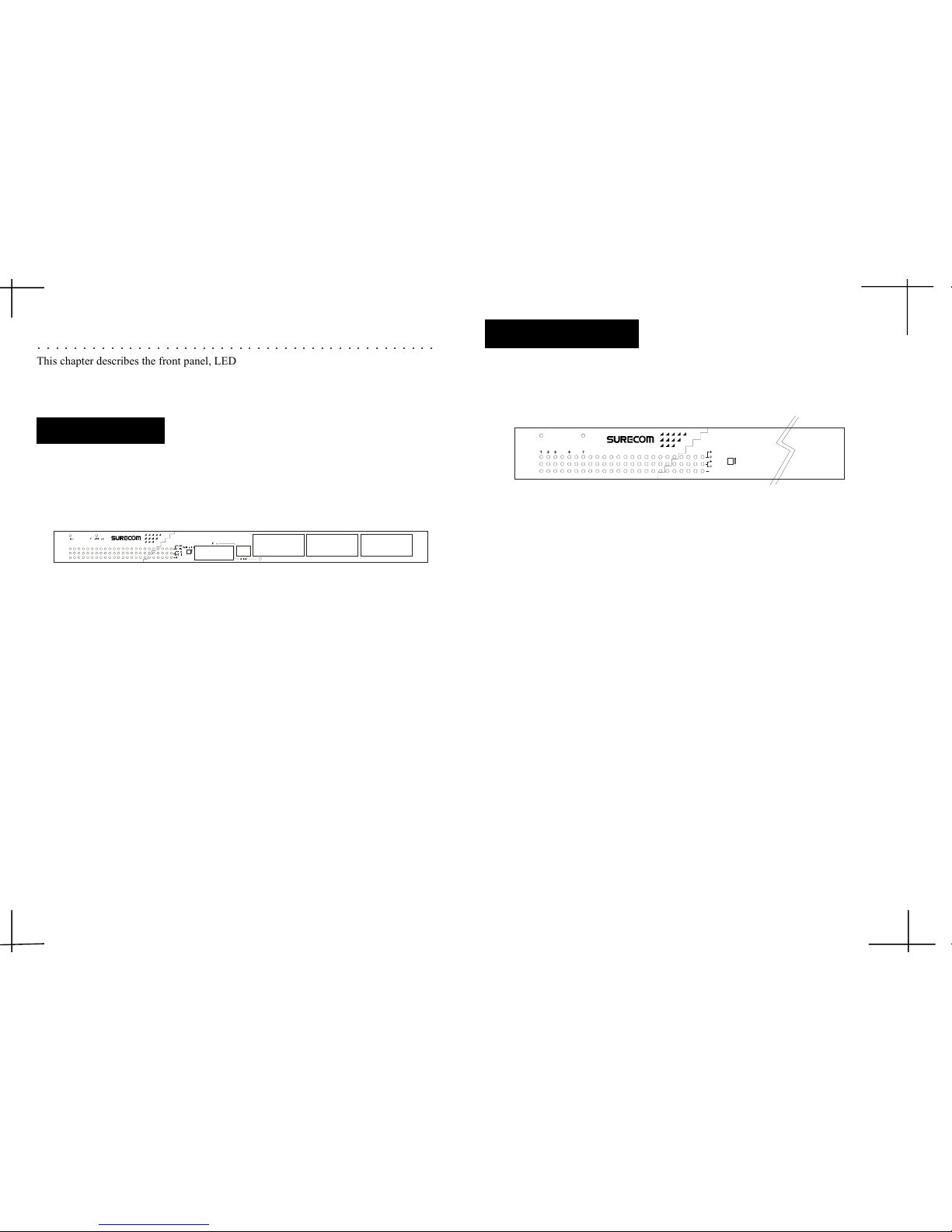
The front panel of the Switch consists of 24 (100/10Mbps MDI-X) ports, 1 Uplink
(MDI) and 1 fiber slide-in ports.
2. Hardware
○○○○○○○○○○○○○○○○○○○○○○○○○○○○○○○○○○○○○○○○○○○○
This chapter describes the front panel, LED indicators, and rear panel on the Switch.
Figure 2-1: Front Panel
2-2
The LED indicators are all located on the front panel which include one Power, one
Fiber Slide-in, one Link/Act., one FDX/Col,and one Speed indicator per port.
Figure 2-2: LED indicators
1. Power
The LED lights when the Switch is powered on. If the LED , fails to light, checkThe LED lights when the Switch is powered on. If the LED , fails to light, check
The LED lights when the Switch is powered on. If the LED , fails to light, checkThe LED lights when the Switch is powered on. If the LED , fails to light, check
The LED lights when the Switch is powered on. If the LED , fails to light, check
the AC power connector to ensure proper insertion of the power cord and thatthe AC power connector to ensure proper insertion of the power cord and that
the AC power connector to ensure proper insertion of the power cord and thatthe AC power connector to ensure proper insertion of the power cord and that
the AC power connector to ensure proper insertion of the power cord and that
the power switch is turned ON.the power switch is turned ON.
the power switch is turned ON.the power switch is turned ON.
the power switch is turned ON.
2.2.
2.2.
2.
Fiber Slide-inFiber Slide-in
Fiber Slide-inFiber Slide-in
Fiber Slide-in
The LED lights to indicate that the optional fiber slide-in module is chosen toThe LED lights to indicate that the optional fiber slide-in module is chosen to
The LED lights to indicate that the optional fiber slide-in module is chosen toThe LED lights to indicate that the optional fiber slide-in module is chosen to
The LED lights to indicate that the optional fiber slide-in module is chosen to
operate the Switch.operate the Switch.
operate the Switch.operate the Switch.
operate the Switch.
3.3.
3.3.
3.
Link/ActLink/Act
Link/ActLink/Act
Link/Act
These LEDs light upThese LEDs light up
These LEDs light upThese LEDs light up
These LEDs light up green
to indicate that a valid link is established. These LEDs to indicate that a valid link is established. These LEDs
to indicate that a valid link is established. These LEDs to indicate that a valid link is established. These LEDs
to indicate that a valid link is established. These LEDs
flash whenever data packets are transmitting or receiving.flash whenever data packets are transmitting or receiving.
flash whenever data packets are transmitting or receiving.flash whenever data packets are transmitting or receiving.
flash whenever data packets are transmitting or receiving.
4. FDX/Col
These LEDs light upThese LEDs light up
These LEDs light upThese LEDs light up
These LEDs light up green
to show the ports are operating in full-duplex (FDX)to show the ports are operating in full-duplex (FDX)
to show the ports are operating in full-duplex (FDX)to show the ports are operating in full-duplex (FDX)
to show the ports are operating in full-duplex (FDX)
mode. These LEDs flash whenever collision is detected on the netwok segments.mode. These LEDs flash whenever collision is detected on the netwok segments.
mode. These LEDs flash whenever collision is detected on the netwok segments.mode. These LEDs flash whenever collision is detected on the netwok segments.
mode. These LEDs flash whenever collision is detected on the netwok segments.
5. Speed
These LEDs light when the ports run at 100Mbps. These LEDs are OFF when theyThese LEDs light when the ports run at 100Mbps. These LEDs are OFF when they
These LEDs light when the ports run at 100Mbps. These LEDs are OFF when theyThese LEDs light when the ports run at 100Mbps. These LEDs are OFF when they
These LEDs light when the ports run at 100Mbps. These LEDs are OFF when they
run at 10Mbps or are not connected.run at 10Mbps or are not connected.
run at 10Mbps or are not connected.run at 10Mbps or are not connected.
run at 10Mbps or are not connected.
LED Indicators
2-12-1
2-12-1
2-1
Front Panel
13 14 15
1
234
5678
9101112
16 17 18 19 20
21 22 23 24
1
23 54 6 7 8 9 10 11 12 13 14 15 16 17 18 19 20 21 22 23 24
EP-82 4DX-CS
24
-Port 100/10M N-Way 19" R a ck-Mount Smart Switch
Page 6
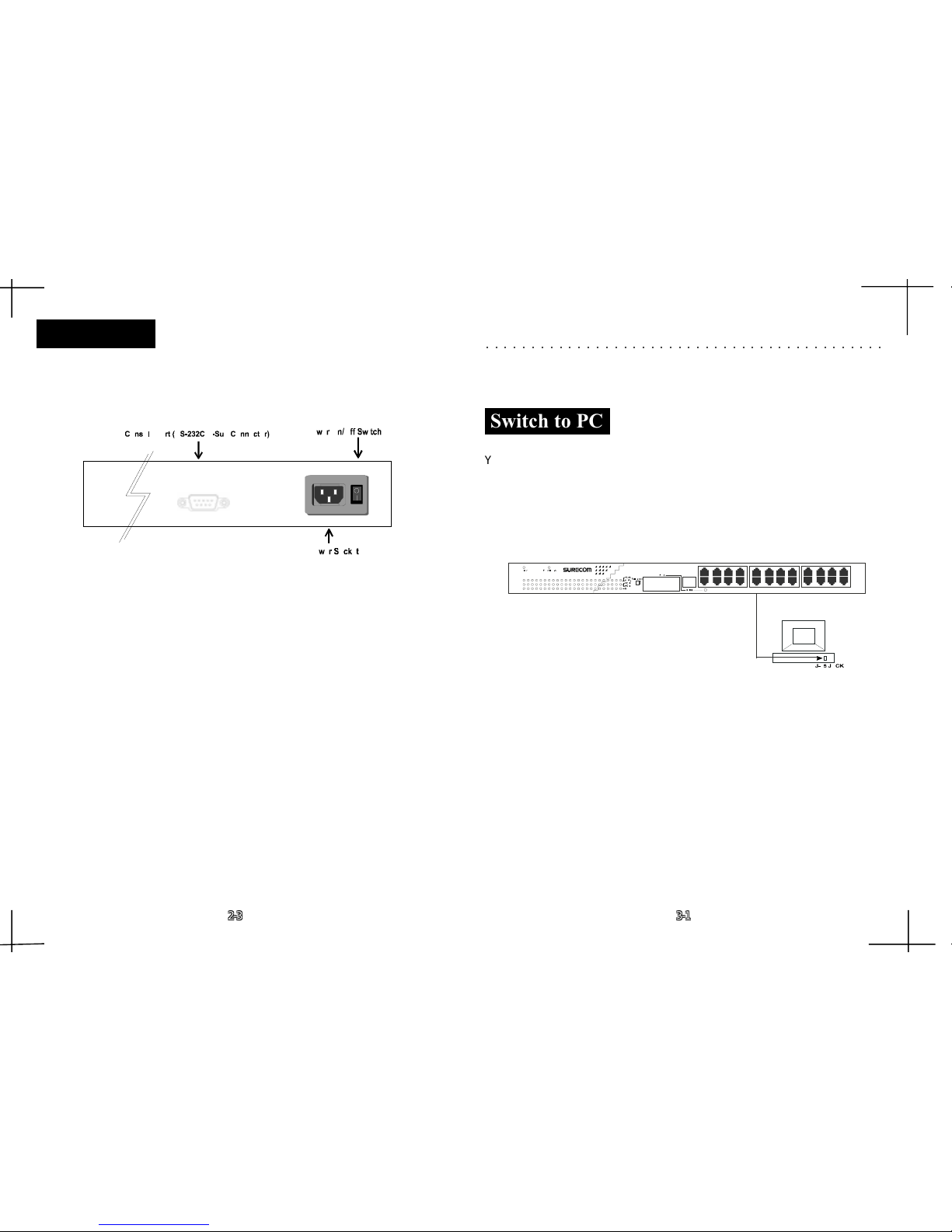
The rear panel consists of an AC power socket, a power switch, and a console port.The rear panel consists of an AC power socket, a power switch, and a console port.
The rear panel consists of an AC power socket, a power switch, and a console port.The rear panel consists of an AC power socket, a power switch, and a console port.
The rear panel consists of an AC power socket, a power switch, and a console port.
TT
TT
T
wo system fans are located at the both sides of the Switch.wo system fans are located at the both sides of the Switch.
wo system fans are located at the both sides of the Switch.wo system fans are located at the both sides of the Switch.
wo system fans are located at the both sides of the Switch.
Figure 2-3: Rear PanelFigure 2-3: Rear Panel
Figure 2-3: Rear PanelFigure 2-3: Rear Panel
Figure 2-3: Rear Panel
Rear Panel
1. Power Socket
Plugs the power cord into this socket.Plugs the power cord into this socket.
Plugs the power cord into this socket.Plugs the power cord into this socket.
Plugs the power cord into this socket.
2. Power On/off Switch
To turn the power on or off.To turn the power on or off.
To turn the power on or off.To turn the power on or off.
To turn the power on or off.
2-32-
CHAPTER 3
Network DIY
ThisThis
ThisThis
This
chapter describes how to connect this Switch to your Fast Ethernet network. chapter describes how to connect this Switch to your Fast Ethernet network.
chapter describes how to connect this Switch to your Fast Ethernet network. chapter describes how to connect this Switch to your Fast Ethernet network.
chapter describes how to connect this Switch to your Fast Ethernet network.
3. Network Connections
Figure 3-1: PC or Workstation ConnectionFigure 3-1: PC or Workstation Connection
Figure 3-1: PC or Workstation ConnectionFigure 3-1: PC or Workstation Connection
Figure 3-1: PC or Workstation Connection
Make sure you have installed a 10BASE-T or 100BASE-TX network interface cardMake sure you have installed a 10BASE-T or 100BASE-TX network interface card
Make sure you have installed a 10BASE-T or 100BASE-TX network interface cardMake sure you have installed a 10BASE-T or 100BASE-TX network interface card
Make sure you have installed a 10BASE-T or 100BASE-TX network interface card
for connecting a PC to the Switch’for connecting a PC to the Switch’
for connecting a PC to the Switch’for connecting a PC to the Switch’
for connecting a PC to the Switch’
s RJ-45 (MDI-X) station ports. If LEDs don’s RJ-45 (MDI-X) station ports. If LEDs don’
s RJ-45 (MDI-X) station ports. If LEDs don’s RJ-45 (MDI-X) station ports. If LEDs don’
s RJ-45 (MDI-X) station ports. If LEDs don’
tt
tt
t
light after powering on the Switch, check if the LAN card, the cable and connectorslight after powering on the Switch, check if the LAN card, the cable and connectors
light after powering on the Switch, check if the LAN card, the cable and connectorslight after powering on the Switch, check if the LAN card, the cable and connectors
light after powering on the Switch, check if the LAN card, the cable and connectors
are properly attached to the PC and the Switch.are properly attached to the PC and the Switch.
are properly attached to the PC and the Switch.are properly attached to the PC and the Switch.
are properly attached to the PC and the Switch.
When a attached PC is powered on or reset:When a attached PC is powered on or reset:
When a attached PC is powered on or reset:When a attached PC is powered on or reset:
When a attached PC is powered on or reset:
1.1.
1.1.
1.
The Link/Act LED will lightThe Link/Act LED will light
The Link/Act LED will lightThe Link/Act LED will light
The Link/Act LED will light
2.2.
2.2.
2.
The FDX/Col LED depends on the installed LAN card’The FDX/Col LED depends on the installed LAN card’
The FDX/Col LED depends on the installed LAN card’The FDX/Col LED depends on the installed LAN card’
The FDX/Col LED depends on the installed LAN card’
s capabilities for the PCs capabilities for the PC
s capabilities for the PCs capabilities for the PC
s capabilities for the PC
and the Switch connection. and the Switch connection.
and the Switch connection. and the Switch connection.
and the Switch connection.
3.3.
3.3.
3.
The 100M LED will light for 100Mbps connection, otherwise it will be unlighted.The 100M LED will light for 100Mbps connection, otherwise it will be unlighted.
The 100M LED will light for 100Mbps connection, otherwise it will be unlighted.The 100M LED will light for 100Mbps connection, otherwise it will be unlighted.
The 100M LED will light for 100Mbps connection, otherwise it will be unlighted.
○○○○○○○○○○○○○○○○○○○○○○○○○○○○○○○○○○○○○○○○○○○○
2-32-3
2-32-3
2-3
3-13-1
3-13-1
3-1
Switch to PC
YY
YY
Y
ou can connect any RJ-45 (MDI-X) station port on the Switch to a PC viaou can connect any RJ-45 (MDI-X) station port on the Switch to a PC via
ou can connect any RJ-45 (MDI-X) station port on the Switch to a PC viaou can connect any RJ-45 (MDI-X) station port on the Switch to a PC via
ou can connect any RJ-45 (MDI-X) station port on the Switch to a PC via
twisted-pair cable with RJ-45 plugs at both ends. Use 100 Category 3, 4 or 5 cabletwisted-pair cable with RJ-45 plugs at both ends. Use 100 Category 3, 4 or 5 cable
twisted-pair cable with RJ-45 plugs at both ends. Use 100 Category 3, 4 or 5 cabletwisted-pair cable with RJ-45 plugs at both ends. Use 100 Category 3, 4 or 5 cable
twisted-pair cable with RJ-45 plugs at both ends. Use 100 Category 3, 4 or 5 cable
for standard 10Mbps Ethernet connections, or 100 Category 5 cable for 100Mbpsfor standard 10Mbps Ethernet connections, or 100 Category 5 cable for 100Mbps
for standard 10Mbps Ethernet connections, or 100 Category 5 cable for 100Mbpsfor standard 10Mbps Ethernet connections, or 100 Category 5 cable for 100Mbps
for standard 10Mbps Ethernet connections, or 100 Category 5 cable for 100Mbps
Fast Ethernet connections.Fast Ethernet connections.
Fast Ethernet connections.Fast Ethernet connections.
Fast Ethernet connections.
£[£[
£[£[
£[
£[£[
£[£[
£[
3. Console Port (RS-232C D-Sub Connector)
Connects a normal RS-232C Serial DB9 Cable to this console port connector. Connects a normal RS-232C Serial DB9 Cable to this console port connector.
Connects a normal RS-232C Serial DB9 Cable to this console port connector. Connects a normal RS-232C Serial DB9 Cable to this console port connector.
Connects a normal RS-232C Serial DB9 Cable to this console port connector.
13 14 15
1
234
5678
9101112
16 17 18 19 20
21 22 23 24
1 23 54 6789101112131415161718192021222324
EP-824DX-CS
24
-Port 100/10M N-Way 19" Rack-Mount Smart Switch
Page 7
3-2
3-33-3
3-33-3
3-3
Switch to Hub
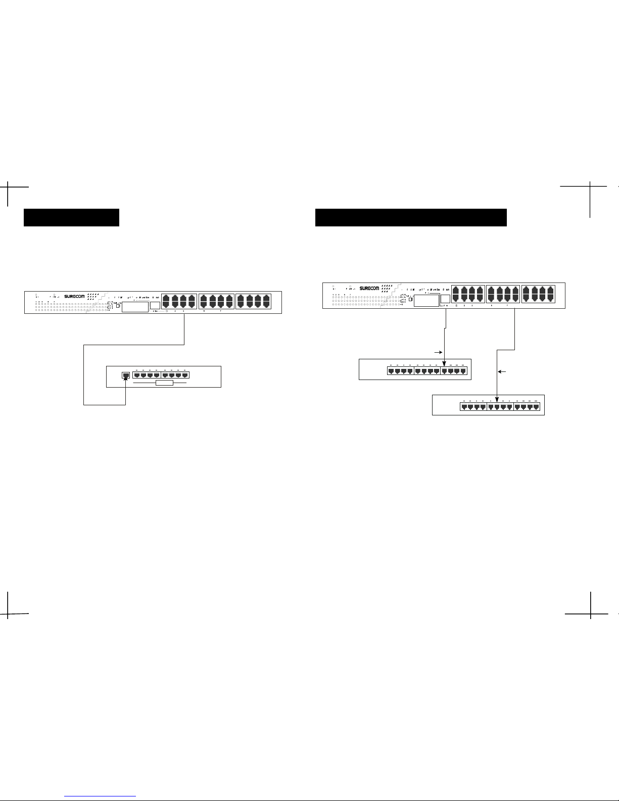
Figure 3-2: 10BASE-T or 100BASE-TX Hub ConnectionFigure 3-2: 10BASE-T or 100BASE-TX Hub Connection
Figure 3-2: 10BASE-T or 100BASE-TX Hub ConnectionFigure 3-2: 10BASE-T or 100BASE-TX Hub Connection
Figure 3-2: 10BASE-T or 100BASE-TX Hub Connection
(10BASE-T Hub)
The Link/Act LED will lightThe Link/Act LED will light
The Link/Act LED will lightThe Link/Act LED will light
The Link/Act LED will light
The FDX/Col LED will be unlightedThe FDX/Col LED will be unlighted
The FDX/Col LED will be unlightedThe FDX/Col LED will be unlighted
The FDX/Col LED will be unlighted
The LED speed LED will be unlightedThe LED speed LED will be unlighted
The LED speed LED will be unlightedThe LED speed LED will be unlighted
The LED speed LED will be unlighted
(100BASE-TX Hub)
The Link/Act LED will lightThe Link/Act LED will light
The Link/Act LED will lightThe Link/Act LED will light
The Link/Act LED will light
The FDX/Col LED will be unlightedThe FDX/Col LED will be unlighted
The FDX/Col LED will be unlightedThe FDX/Col LED will be unlighted
The FDX/Col LED will be unlighted
The LED speed will lightThe LED speed will light
The LED speed will lightThe LED speed will light
The LED speed will light
Hub without Uplink (MDI) Port
If a hub is not equipped with an Uplink (MDI) port, then connection If a hub is not equipped with an Uplink (MDI) port, then connection
If a hub is not equipped with an Uplink (MDI) port, then connection If a hub is not equipped with an Uplink (MDI) port, then connection
If a hub is not equipped with an Uplink (MDI) port, then connection
can be madecan be made
can be madecan be made
can be made
using either straight cable or crossover cable (see Appendix A, using either straight cable or crossover cable (see Appendix A,
using either straight cable or crossover cable (see Appendix A, using either straight cable or crossover cable (see Appendix A,
using either straight cable or crossover cable (see Appendix A,
TT
TT
T
echnical Specifications forechnical Specifications for
echnical Specifications forechnical Specifications for
echnical Specifications for
cable requirements).cable requirements).
cable requirements).cable requirements).
cable requirements).
Figure 3-3: Connecting to a Hub without Uplink PortFigure 3-3: Connecting to a Hub without Uplink Port
Figure 3-3: Connecting to a Hub without Uplink PortFigure 3-3: Connecting to a Hub without Uplink Port
Figure 3-3: Connecting to a Hub without Uplink Port
Using a straight cable
When using a straight cable, the connection can be made from the Uplink port onWhen using a straight cable, the connection can be made from the Uplink port on
When using a straight cable, the connection can be made from the Uplink port onWhen using a straight cable, the connection can be made from the Uplink port on
When using a straight cable, the connection can be made from the Uplink port on
the Switch to any normal port on a Hub (see figure 3-3).the Switch to any normal port on a Hub (see figure 3-3).
the Switch to any normal port on a Hub (see figure 3-3).the Switch to any normal port on a Hub (see figure 3-3).
the Switch to any normal port on a Hub (see figure 3-3).
Using a crossover cable
When using a crossover cable, the connection can be made from any RJ-45 portWhen using a crossover cable, the connection can be made from any RJ-45 port
When using a crossover cable, the connection can be made from any RJ-45 portWhen using a crossover cable, the connection can be made from any RJ-45 port
When using a crossover cable, the connection can be made from any RJ-45 port
(MDI-X) port on the Switch to any normal on a Hub (see figure 3-3).(MDI-X) port on the Switch to any normal on a Hub (see figure 3-3).
(MDI-X) port on the Switch to any normal on a Hub (see figure 3-3).(MDI-X) port on the Switch to any normal on a Hub (see figure 3-3).
(MDI-X) port on the Switch to any normal on a Hub (see figure 3-3).
Hub A
Hub B
Str a ight Ca ble
Crossover Cable
Hub
100/10M
YY
YY
Y
ou can connect any RJ-45 (MDI-X) station port on the Switch to the Uplink port of aou can connect any RJ-45 (MDI-X) station port on the Switch to the Uplink port of a
ou can connect any RJ-45 (MDI-X) station port on the Switch to the Uplink port of aou can connect any RJ-45 (MDI-X) station port on the Switch to the Uplink port of a
ou can connect any RJ-45 (MDI-X) station port on the Switch to the Uplink port of a
Hub via straight cable with RJ-45 plugs at both ends. Use 100 Category 3, 4 or 5Hub via straight cable with RJ-45 plugs at both ends. Use 100 Category 3, 4 or 5
Hub via straight cable with RJ-45 plugs at both ends. Use 100 Category 3, 4 or 5Hub via straight cable with RJ-45 plugs at both ends. Use 100 Category 3, 4 or 5
Hub via straight cable with RJ-45 plugs at both ends. Use 100 Category 3, 4 or 5
cable for standard 10Mbps Ethernet connections, or 100 Category 5 cable forcable for standard 10Mbps Ethernet connections, or 100 Category 5 cable for
cable for standard 10Mbps Ethernet connections, or 100 Category 5 cable forcable for standard 10Mbps Ethernet connections, or 100 Category 5 cable for
cable for standard 10Mbps Ethernet connections, or 100 Category 5 cable for
100Mbps Fast Ethernet connections.100Mbps Fast Ethernet connections.
100Mbps Fast Ethernet connections.100Mbps Fast Ethernet connections.
100Mbps Fast Ethernet connections.
£[£[
£[£[
£[
£[£[
£[£[
£[
When a attached 10BASE-T/100BASE-TX Hub is powered on or reset:When a attached 10BASE-T/100BASE-TX Hub is powered on or reset:
When a attached 10BASE-T/100BASE-TX Hub is powered on or reset:When a attached 10BASE-T/100BASE-TX Hub is powered on or reset:
When a attached 10BASE-T/100BASE-TX Hub is powered on or reset:
Page 8
3-4 3-4
3-4 3-4
3-4
Switch to Switch (Other Devices)
The Switch can be connected to another Switch or other devices (Routers, Bridges,The Switch can be connected to another Switch or other devices (Routers, Bridges,
The Switch can be connected to another Switch or other devices (Routers, Bridges,The Switch can be connected to another Switch or other devices (Routers, Bridges,
The Switch can be connected to another Switch or other devices (Routers, Bridges,
etc.) via a twisted-pair category 3, 4, 5 UTP/STP straight or crossover cable.etc.) via a twisted-pair category 3, 4, 5 UTP/STP straight or crossover cable.
etc.) via a twisted-pair category 3, 4, 5 UTP/STP straight or crossover cable.etc.) via a twisted-pair category 3, 4, 5 UTP/STP straight or crossover cable.
etc.) via a twisted-pair category 3, 4, 5 UTP/STP straight or crossover cable.
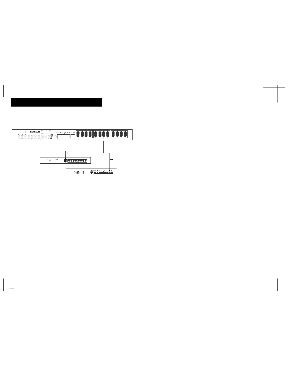
Figure 3-4 Switch to Switch ConnectionFigure 3-4 Switch to Switch Connection
Figure 3-4 Switch to Switch ConnectionFigure 3-4 Switch to Switch Connection
Figure 3-4 Switch to Switch Connection
Straight Cable
Crossover Cable
FDX/ ColFDX/ Col
100/1 0 M SWITC H A
FDX/ ColFDX/ Col
100/1 0 M SWITC H B
±µP. 4 - 1
Using a straight cable
When using a straight cable, any RJ-45 (MDI-X) port on the Switch can beWhen using a straight cable, any RJ-45 (MDI-X) port on the Switch can be
When using a straight cable, any RJ-45 (MDI-X) port on the Switch can beWhen using a straight cable, any RJ-45 (MDI-X) port on the Switch can be
When using a straight cable, any RJ-45 (MDI-X) port on the Switch can be
connected to the Uplink port on any 10Mbps or 100Mbps Switch (Switch A) or otherconnected to the Uplink port on any 10Mbps or 100Mbps Switch (Switch A) or other
connected to the Uplink port on any 10Mbps or 100Mbps Switch (Switch A) or otherconnected to the Uplink port on any 10Mbps or 100Mbps Switch (Switch A) or other
connected to the Uplink port on any 10Mbps or 100Mbps Switch (Switch A) or other
devices. (See Figure 3-4).devices. (See Figure 3-4).
devices. (See Figure 3-4).devices. (See Figure 3-4).
devices. (See Figure 3-4).
Using a crossover cable
When using a crossover cable, any RJ-45 (MDI-X) port on the Switch can beWhen using a crossover cable, any RJ-45 (MDI-X) port on the Switch can be
When using a crossover cable, any RJ-45 (MDI-X) port on the Switch can beWhen using a crossover cable, any RJ-45 (MDI-X) port on the Switch can be
When using a crossover cable, any RJ-45 (MDI-X) port on the Switch can be
connected to any normal port on any 10Mbps or 100Mbps Switch (Switch B) or otherconnected to any normal port on any 10Mbps or 100Mbps Switch (Switch B) or other
connected to any normal port on any 10Mbps or 100Mbps Switch (Switch B) or otherconnected to any normal port on any 10Mbps or 100Mbps Switch (Switch B) or other
connected to any normal port on any 10Mbps or 100Mbps Switch (Switch B) or other
devices. (See Figure 3-4).devices. (See Figure 3-4).
devices. (See Figure 3-4).devices. (See Figure 3-4).
devices. (See Figure 3-4).
When a Switch or other devices is switched on:When a Switch or other devices is switched on:
When a Switch or other devices is switched on:When a Switch or other devices is switched on:
When a Switch or other devices is switched on:
The Link/Act LED will lightThe Link/Act LED will light
The Link/Act LED will lightThe Link/Act LED will light
The Link/Act LED will light
The FDX/Col LED depends on the attached Switch or other devices’The FDX/Col LED depends on the attached Switch or other devices’
The FDX/Col LED depends on the attached Switch or other devices’The FDX/Col LED depends on the attached Switch or other devices’
The FDX/Col LED depends on the attached Switch or other devices’
capabilities. capabilities.
capabilities. capabilities.
capabilities.
The 100M LED will light for 100Mbps connection, otherwise it will be The 100M LED will light for 100Mbps connection, otherwise it will be
The 100M LED will light for 100Mbps connection, otherwise it will be The 100M LED will light for 100Mbps connection, otherwise it will be
The 100M LED will light for 100Mbps connection, otherwise it will be
unlighted. unlighted.
unlighted. unlighted.
unlighted.
Page 9

Physical and Environmental
RAM Buffer:
Total 4Mbits per deviceTotal 4Mbits per device
Total 4Mbits per deviceTotal 4Mbits per device
Total 4Mbits per device
Filtering AddressFiltering Address
Filtering AddressFiltering Address
Filtering Address
Table:Table:
Table:Table:
Table:
2 K entries per device2 K entries per device
2 K entries per device2 K entries per device
2 K entries per device
Packet Filtering/ Packet Filtering/
Packet Filtering/ Packet Filtering/
Packet Filtering/
148800/14800pps 148800/14800pps
148800/14800pps 148800/14800pps
148800/14800pps
Forwarding Rate:Forwarding Rate:
Forwarding Rate:Forwarding Rate:
Forwarding Rate:
Wire speed per port (for 100Mbps&10Mbps)Wire speed per port (for 100Mbps&10Mbps)
Wire speed per port (for 100Mbps&10Mbps)Wire speed per port (for 100Mbps&10Mbps)
Wire speed per port (for 100Mbps&10Mbps)
Dimensions:Dimensions:
Dimensions:Dimensions:
Dimensions:
44 x 20 x 4.5 cm (LxWxH)44 x 20 x 4.5 cm (LxWxH)
44 x 20 x 4.5 cm (LxWxH)44 x 20 x 4.5 cm (LxWxH)
44 x 20 x 4.5 cm (LxWxH)
Net Weight:Net Weight:
Net Weight:Net Weight:
Net Weight:
4.2Kg4.2Kg
4.2Kg4.2Kg
4.2Kg
Power:Power:
Power:Power:
Power:
Internal Universal Power,Internal Universal Power,
Internal Universal Power,Internal Universal Power,
Internal Universal Power,
Input:100~240V(47~63Hz); Output:5V/8A Input:100~240V(47~63Hz); Output:5V/8A
Input:100~240V(47~63Hz); Output:5V/8A Input:100~240V(47~63Hz); Output:5V/8A
Input:100~240V(47~63Hz); Output:5V/8A
Consumption:Consumption:
Consumption:Consumption:
Consumption:
30 watts maximum30 watts maximum
30 watts maximum30 watts maximum
30 watts maximum
DC fans:DC fans:
DC fans:DC fans:
DC fans:
2 built-in 40x40 mm fan2 built-in 40x40 mm fan
2 built-in 40x40 mm fan2 built-in 40x40 mm fan
2 built-in 40x40 mm fan
Temperature:Temperature:
Temperature:Temperature:
Temperature:
Operating:Operating:
Operating:Operating:
Operating:
0 ° ~ 55 °C0 ° ~ 55 °C
0 ° ~ 55 °C0 ° ~ 55 °C
0 ° ~ 55 °C
Storage:Storage:
Storage:Storage:
Storage:
0 ° ~ 65 °C0 ° ~ 65 °C
0 ° ~ 65 °C0 ° ~ 65 °C
0 ° ~ 65 °C
Humidity:Humidity:
Humidity:Humidity:
Humidity:
Operating:Operating:
Operating:Operating:
Operating:
10% ~ 90%10% ~ 90%
10% ~ 90%10% ~ 90%
10% ~ 90%
Storage:Storage:
Storage:Storage:
Storage:
5% ~ 95%5% ~ 95%
5% ~ 95%5% ~ 95%
5% ~ 95%
Conformance:Conformance:
Conformance:Conformance:
Conformance:
FCC Class A, CE Mark Class AFCC Class A, CE Mark Class A
FCC Class A, CE Mark Class AFCC Class A, CE Mark Class A
FCC Class A, CE Mark Class A
A. Technical Specifications
○○○○○○○○○○○○○○○○○○○○○○○○○○○○○○○○○○○○○○○○○○○○
A-1A-1
A-1A-1
A-1
A-2A-2
A-2A-2
A-2
General
Standards:
IEEE 802.3 10BASE-T EthernetIEEE 802.3 10BASE-T Ethernet
IEEE 802.3 10BASE-T EthernetIEEE 802.3 10BASE-T Ethernet
IEEE 802.3 10BASE-T Ethernet
IEEE 802.3u 100BASE-TX/FX Fast EthernetIEEE 802.3u 100BASE-TX/FX Fast Ethernet
IEEE 802.3u 100BASE-TX/FX Fast EthernetIEEE 802.3u 100BASE-TX/FX Fast Ethernet
IEEE 802.3u 100BASE-TX/FX Fast Ethernet
ANSI/IEEE Std 802.3 N-way auto-negotiationANSI/IEEE Std 802.3 N-way auto-negotiation
ANSI/IEEE Std 802.3 N-way auto-negotiationANSI/IEEE Std 802.3 N-way auto-negotiation
ANSI/IEEE Std 802.3 N-way auto-negotiation
IEEE 802.3 Frame types: TransparentIEEE 802.3 Frame types: Transparent
IEEE 802.3 Frame types: TransparentIEEE 802.3 Frame types: Transparent
IEEE 802.3 Frame types: Transparent
IEEE 802.3 MAC layer frame size: 64-1518 BytesIEEE 802.3 MAC layer frame size: 64-1518 Bytes
IEEE 802.3 MAC layer frame size: 64-1518 BytesIEEE 802.3 MAC layer frame size: 64-1518 Bytes
IEEE 802.3 MAC layer frame size: 64-1518 Bytes
IEEE 802.3x flow control for Full-DuplexIEEE 802.3x flow control for Full-Duplex
IEEE 802.3x flow control for Full-DuplexIEEE 802.3x flow control for Full-Duplex
IEEE 802.3x flow control for Full-Duplex
Protocol:
CSMA/CDCSMA/CD
CSMA/CDCSMA/CD
CSMA/CD
Topology:
StarStar
StarStar
Star
Transmission
Method:
Store-and-ForwardStore-and-Forward
Store-and-ForwardStore-and-Forward
Store-and-Forward
Transfer Rate:
Ethernet:Ethernet:
Ethernet:Ethernet:
Ethernet:
10M (half-duplex); 20M (full-duplex)10M (half-duplex); 20M (full-duplex)
10M (half-duplex); 20M (full-duplex)10M (half-duplex); 20M (full-duplex)
10M (half-duplex); 20M (full-duplex)
Fast Ethernet:Fast Ethernet:
Fast Ethernet:Fast Ethernet:
Fast Ethernet:
100M (half-duplex); 200M (full-duplex)100M (half-duplex); 200M (full-duplex)
100M (half-duplex); 200M (full-duplex)100M (half-duplex); 200M (full-duplex)
100M (half-duplex); 200M (full-duplex)
Media:
10BASE-T:10BASE-T:
10BASE-T:10BASE-T:
10BASE-T:
UTP Cat. 3,4,5 (Max. cable length100 m);UTP Cat. 3,4,5 (Max. cable length100 m);
UTP Cat. 3,4,5 (Max. cable length100 m);UTP Cat. 3,4,5 (Max. cable length100 m);
UTP Cat. 3,4,5 (Max. cable length100 m);
100BASE-TX:100BASE-TX:
100BASE-TX:100BASE-TX:
100BASE-TX:
UTP Cat. 5 (Max. cable length 100 m);UTP Cat. 5 (Max. cable length 100 m);
UTP Cat. 5 (Max. cable length 100 m);UTP Cat. 5 (Max. cable length 100 m);
UTP Cat. 5 (Max. cable length 100 m);
100BASE-FX:100BASE-FX:
100BASE-FX:100BASE-FX:
100BASE-FX:
Multi-mode Fiber cable (Max. cable length 2,000 m)Multi-mode Fiber cable (Max. cable length 2,000 m)
Multi-mode Fiber cable (Max. cable length 2,000 m)Multi-mode Fiber cable (Max. cable length 2,000 m)
Multi-mode Fiber cable (Max. cable length 2,000 m)
24 100/10Mbps RJ-45 ports24 100/10Mbps RJ-45 ports
24 100/10Mbps RJ-45 ports24 100/10Mbps RJ-45 ports
24 100/10Mbps RJ-45 portsNo. of Ports:
Media Interface
Exchange:
MDI RJ-45 shared with Port # 1MDI RJ-45 shared with Port # 1
MDI RJ-45 shared with Port # 1MDI RJ-45 shared with Port # 1
MDI RJ-45 shared with Port # 1
Page 10
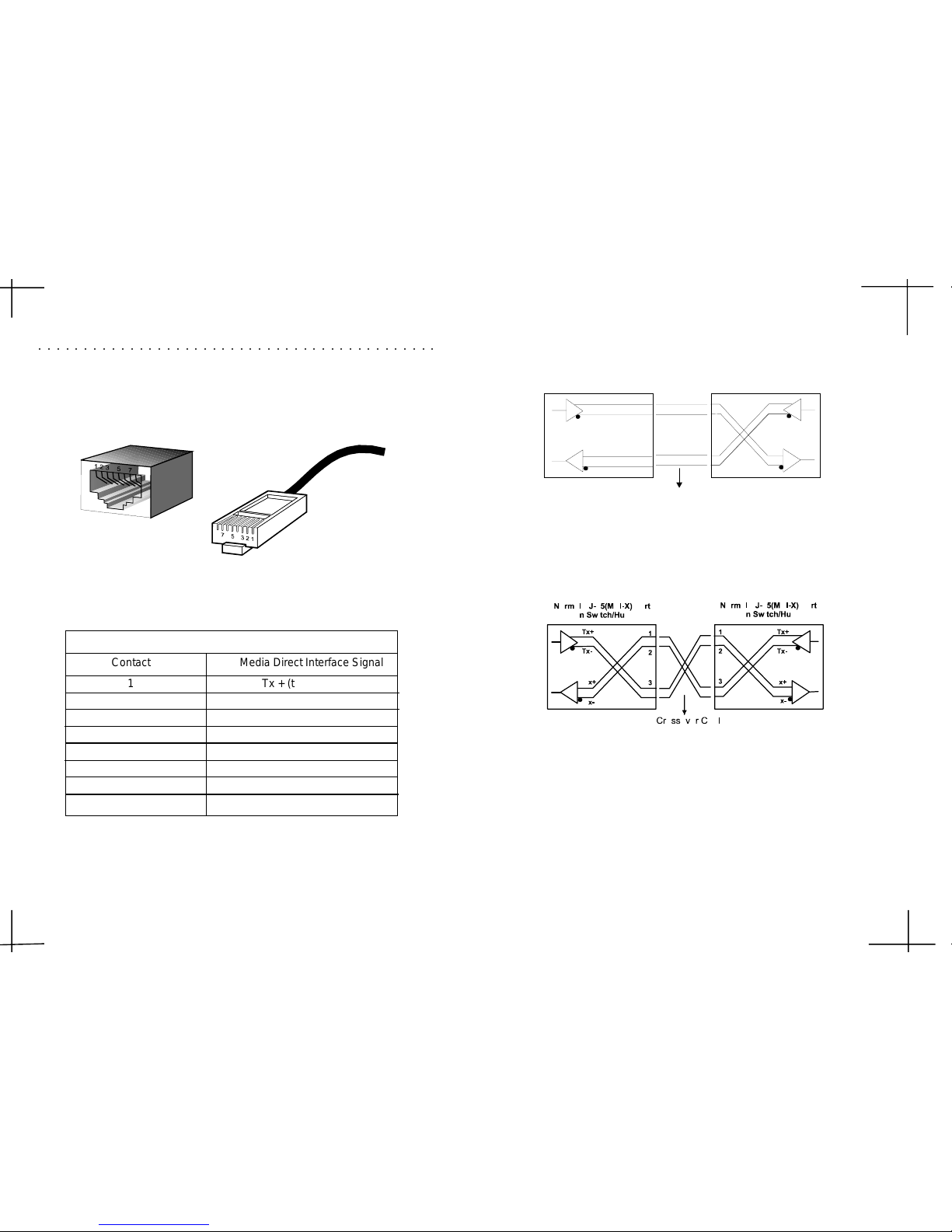
The following shows straight cable and crossover cable connection:The following shows straight cable and crossover cable connection:
The following shows straight cable and crossover cable connection:The following shows straight cable and crossover cable connection:
The following shows straight cable and crossover cable connection:
Rx-
Rx+
Tx-
Tx+
Tx+
Tx-
Rx+
Rx-
1
2
3
6
1
2
3
6
Straight Cable
Up lin k ( MDI) Port on S w itch/Hub
RJ-45 port on Adapter
or
Normal RJ-45(MD I-X) Port
on Switch/Hub
Straight cable for Switch (Uplink MDI port) to Switch/Hub or other
devices connection
B
B
BB
BB
B
--
--
-
22
22
2BBb
Crossover cable for Switch (MDI-X port) to Switch/Hub or other
network devices (MDI-X port) connection
B-1B-1
B-1B-1
B-1
B. Cable Requirements
The following diagram and table show the standard RJ-45 receptacle/connector andThe following diagram and table show the standard RJ-45 receptacle/connector and
The following diagram and table show the standard RJ-45 receptacle/connector andThe following diagram and table show the standard RJ-45 receptacle/connector and
The following diagram and table show the standard RJ-45 receptacle/connector and
their pin assignments for the switch-to-network interface card connection, and thetheir pin assignments for the switch-to-network interface card connection, and the
their pin assignments for the switch-to-network interface card connection, and thetheir pin assignments for the switch-to-network interface card connection, and the
their pin assignments for the switch-to-network interface card connection, and the
straight/crossover cable for the Switch-to-switch/hub/bridge connection.straight/crossover cable for the Switch-to-switch/hub/bridge connection.
straight/crossover cable for the Switch-to-switch/hub/bridge connection.straight/crossover cable for the Switch-to-switch/hub/bridge connection.
straight/crossover cable for the Switch-to-switch/hub/bridge connection.
The standard RJ-45 receptacle/connector
○○○○○○○○○○○○○○○○○○○○○○○○○○○○○○○○○○○○○○○○○○○○
Contact Media Direct Interface Signal
1 Tx + (transmit)
2 Tx - (transmit)
3 Rx + (receive)
4 Not used
5 Not used
6 Rx - (receive)
7 Not used
8 Not used
The standard Category 3 cable, RJ-45 pin assignment
RJ-45 Connector pin assignment
 Loading...