

Page 1

EP-816DX-FW
16-Port 10/100M Ethernet
Rack-Mount Web Smart Switch
with Fiber Support
User Guide
#481816DXFWZ0
Page 2

2
FCC Statement
This equipment can generate, use and radiate radio frequency energy and, if not installed and used
in accordance with the instructions in this manual, may cause interference to radio communications.
This equipment has been tested and found to comply with the limits for a Class A computing device
pursuant to Part 15 of the FCC rules, which are designed to provide reasonable protection against
radio interference when operated in a commercial environment. Operation of this equipment in a
residential area is likely to cause interference, in which case the user, at his own expense, will be
required to take whatever measures are necessary to correct the interference.
WARNING! Any changes or modifications to this product not expressly approved by the
manufacturer could void any assurances of safety or performance and could result in
violation of Part 15 of the FCC Rules.
CE Declaration of conformity
This is a Class A product. In a domestic environment product m ay cause radio interference in which
case the user may be required to take adequate measures.
Trademarks
All company, brand, and product names are trademarks or registered trademarks of their respective
companies.
WEEE
To avoid the potential effects on the environment and human health as a result of the
presence of hazardous substances in electrical and electronic equipment, end users of
electrical and electronic equipment should understand the meaning of the crossed-out
wheeled bin symbol. Do not dispose of WEEE as unsorted municipal waste and have to
collect such WEEE separately.
Page 3

3
Contents
1. Introduction....................................................................................................................................4
1.1 Feature and Benefit..............................................................................................................4
1.2 Technical Specification ........................................................................................................6
1.3 Package Contents.................................................................................................................7
1.4 Glossary ................................................................................................................................7
2. Hardware Installation..................................................................................................................10
2.1 Overview.............................................................................................................................10
2.2 Hardware Connection........................................................................................................12
3. Using Configuration Menu..........................................................................................................14
3.1 Software Installation..........................................................................................................14
3.2 Using RRCP........................................................................................................................14
3.3 Network : ............................................................................................................................15
3.3.1 Switch Selection.......................................................................................................15
3.3.2 Switch Database......................................................................................................18
3.4 Switch Status :....................................................................................................................19
3.4.1 Port Status :.............................................................................................................19
3.4.2 MIB Information: ...................................................................................................20
3.4.3 Cable Tester : ..........................................................................................................21
3.4.4 Signal Quality :........................................................................................................22
3.5 Switch Configuration.........................................................................................................23
3.5.1 Global Configuration:.............................................................................................23
3.5.2 Port Configuration: ................................................................................................24
3.5.3 QoS function:...........................................................................................................26
3.5.4 VLAN Configuration:.............................................................................................27
3.5.5 Port Mirror Configuration:...................................................................................32
3.5.6 Security configuration:...........................................................................................33
3.6 Switch Internals :...............................................................................................................34
3.6.1 Load Factory Default Configuration.....................................................................34
3.6.2 Save Configuration to Hardware...........................................................................34
3.6.3 Reset Switch.............................................................................................................34
Page 4

4
1. Introduction
The 16-Port 100/10M N-Way Rack-Mount Smart Switch is the latest design in its N-Way
Switches series for easy installation and high-performance in an environment where traffic on the
network and the number of users increase continuously. Provide 16-Port 100/10M Ethernet Switch
support Auto MDI/MDI-X. Small businesses and corporate branch offices can take full advantage
of 100Mbps Fast Ethernet performance and preserve existing desktop investment with no changes
required to PCs, NICs, cabling,drivers, or PC configurations.
1.1 Feature and Benefit
Feature
1. Provide 16-Port 100/10M Ethernet Switch to support Auto MDI/MDI-X
2. Provide one fiber slide-in port for expansion the workgroup distance to 2,000 meters
3. Provide back-pressure in half-duplex and flow control in full-duplex
4. Store-and-forward switching scheme capability supports rate adaptation and ensures data
integrity
5. N-way Auto-negotiation on each RJ-45 port. This allows for auto-sensing of speed
(100/10Mbps) and auto-detecting mode (full-duplex or half-duplex) thereby providing
you with automatic and flexible solutions in your network connections
6. Auto-polarity detection for correction of incorrect polarity on the received twisted-pair
7. Data fowarding rate 148,800 pps per port at 100% of wire-speed
8. Data filtering rate eliminates all error packets, runts, etc. at 148,800pps per port at 100% of wire
speed
9. Conform to IEEE 802.3 10BASE-T, IEEE 802.3u 100BASE-TX /FX, and IEEE 802.3x
flow control for full-duplex standards
10. Provide non-blocking sixteen ports full-wire speed access
11. Support one fiber slide-in port for expansion with the 16th port
12. Full/half-duplex mode operation on all ports
13. Auto-negotiation capability
14. Source address learning and aging function
15. Provide 8K MAC address and 1.25Mbits SSRAM buffer
16. LEDs to indicate Power, link/activity, full-duplex/collision, and 100 status
17. Support up to 32 VLAN groups for port pased VLAN.
Page 5

5
Benefit
Fiber Slide-in Slot
The Switch has fiber. With fiber the workgroup distance could be extended to 2,000 meters and
solve the distance limit.
Full/Half-Duplex and Easy Expansion
The Switch supports both full/half-duplex on all ports which are able to provide 200Mbps of
bandwidth to the connected devices using auto-negotiation. The Switches also expandable by
cascading two or more switches together or connecting any RJ-45 (MDI-X) port on the Switch to
any device such as a workstation or a server.
Store-and-Forward Scheme
The Switch uses store-and forward switching to ensure all error packets will be filtered and
maintain maximum data integrity, even under heavy loading.
Upgrade
Designed for plug-and-play, the Switch is fully compatible with existing Ethernet networks, thus
saving your current network properties. The 16-Port 10/100M Ethernet Rack-Mount Web Smart
Switch offers a solution in accelerating Ethernet workgroup’s bandwidth.
Remote Control Protocol
Remote Control Protocol is a simple control protocol and window based proposed to enhance
the functionalities of configuration and management. This easily-using program provides completed
smart function for small medium business. Such as VLAN、Trunk、Class of Service、
Bandwidth Control …etc. With these functions, the network bandwidth will be utilized more
efficiently and management will be more convenient.
Page 6

6
1.2 Technical Specification
Standards: IEEE 802.3 10BASE-T Ethernet
IEEE 802.3u 100BASE-TX/FX Fast Ethernet
ANSI/IEEE Std 802.3 N-way auto-negotiation
IEEE 802.3x flow control for Full-Duplex
Protocol: CSMA/CD
Topology: Star
Transmission Method: Store-and Forward
Transfer Rate
Ethernet:
Fast Ethernet:
10M(half-duplex); 20M(full-duplex)
100M(half-duplex); 200M(full-duplex)
Media
10BASE-T:
100BASE-TX:
100BASE-FX:
UTP Cat.3,4,5 (Max. cable length 100m);
UTP Cat.5 (Max. cable length 100m);
Multi-mode Fiber cable (Max. cable length 2000m)
Single-mode Fiber cable(Max. cable length 30 or 60 km)
No. of Ports: 16 100/10M bps RJ-45 ports
Media Interface Exchange: 16 RJ-45 ports support Auto MDI/MDI-X
Port Module Option: Side-in slot for 100M fiber module
RAM Buffer: Total 1.25M bits per device
Filtering Address T able: 8K
Packet Filtering
/Forwarding Rate:
148800/14800pps
Wire speed per port (for 100Mbps & 10Mbps)
Power: Internal Universal Power,
Input: 90-264V(47-63Hz); Output: 3.3V/5A
Consumption: 10 watts maximum
Temperature
Operating:
Storage:
0℃ ~ 45℃
0℃ ~ 60℃
Humidity
Operating:
Storage:
10% ~ 90%
5% ~ 95%
Conformance: FCC Class A, CE Mark Class A
Page 7

7
1.3 Package Contents
1. 16-Port Ethernet Rack-Mount Switch
2. One CD-ROM (Manual and Management Tool included)
3. One Power Cord
4. One Pack of Screws
5. Two Mounting Brackets
Note: If any item is damaged or missing, please contact your supplier.
1.4 Glossary
10BASE-T
IEEE 802.3 specification for 10 Mbps Ethernet over two pairs of Category 3, 4, or 5 UTP cable.
100BASE-TX
IEEE 802.3u specification for 100 Mbps Fast Ethernet over two pairs of Category 5 UTP cable.
Ethernet
A network communication system developed and standardized by DEC, Intel, and Xerox, using
baseband transmission, CSMA/CD access, logical bus topology, and coaxial cable. The successor
IEEE 802.3 standard provides for integration into the OSI model and extends the physical layer and
media with repeaters and implementations that operate on fiber, thin coax and twisted-pair
cable.
Fast Ethernet
A 100 Mbps network communication system based on Ethernet and the CSMA/CD access method.
Media Access Control (MAC)
A portion of the networking protocol that governs access to the transmission medium, facilitating
the exchange of data between network nodes.
Auto-negotiation
Signalling method allowing each node to select its optimum operational mode (e.g., 10 Mbps or
100 Mbps and half or full duplex) based on the capabilities of the node to which it is connected.
Page 8

8
Bandwidth
The difference between the highest and lowest frequencies available for network signals. Also
synonymous with wire speed, the actual speed of the data transmission along the cable.
CSMA/CD
Carrier Sense Multiple Access/Collision Detect is the communication method employed by
Ethernet and Fast Ethernet.
Full Duplex
Transmission method that allows switch and network card to transmit and receive concurrently,
effectively doubling the bandwidth of that link.
Port T runk
Defines a network link aggregation and trunking method which specifies how to create a single
high-speed logical link that combines several lower-speed physical links.
Virtual LAN (VLAN)
A Virtual LAN is a collection of network nodes that share the same collision domain regardless of
their physical location or connection point in the network. A VLAN serves as a logical workgroup
with no physical barriers, and allows users to share information and resources as though located on
the same LAN.
IEEE 802.1Q
VLAN Tagging—Defines Ethernet frame tags which carry VLAN information. It allows
switches to assign endstations to different virtual LANs, and defines a standard way for VLANs to
communicate across switched networks.
IEEE 802.1p
An IEEE standard for providing quality of service (QoS) in Ethernet networks. The standard
uses packet tags that define up to eight traffic classes and allows switches to transmit packets based
on the tagged priority value.
Port Mirroring
A method whereby data on a target port is mirrored to a monitor port for troubleshooting with a
logic analyzer or RMON probe. This allows data on the target port to be studied unobstructively.
Page 9

9
Bandwidth Control
This function allows the network manager to control the maximum rate for traffic transmitted
or received on an interface. Rate limiting is configured on interfaces at the edge of a network to
limit traffic into or out of the network. Traffic that falls within the rate limit is transmitted, while
packets that exceed the acceptable amount of traffic are dropped.
IGMP Snooping
Listening to IGMP Query and IGMP Report packets transferred between IP Multicast Routers
and IP Multicast host groups to identify IP Multicast group members.
Internet Group Management Protocol (IGMP)
A protocol through which hosts can register with their local router for multicast services. If there
is more than one multicast router on a given subnetwork, one of the routers is made the “querier”
and assumes responsibility for keeping track of group membership.
Page 10
10
2. Hardware Installation
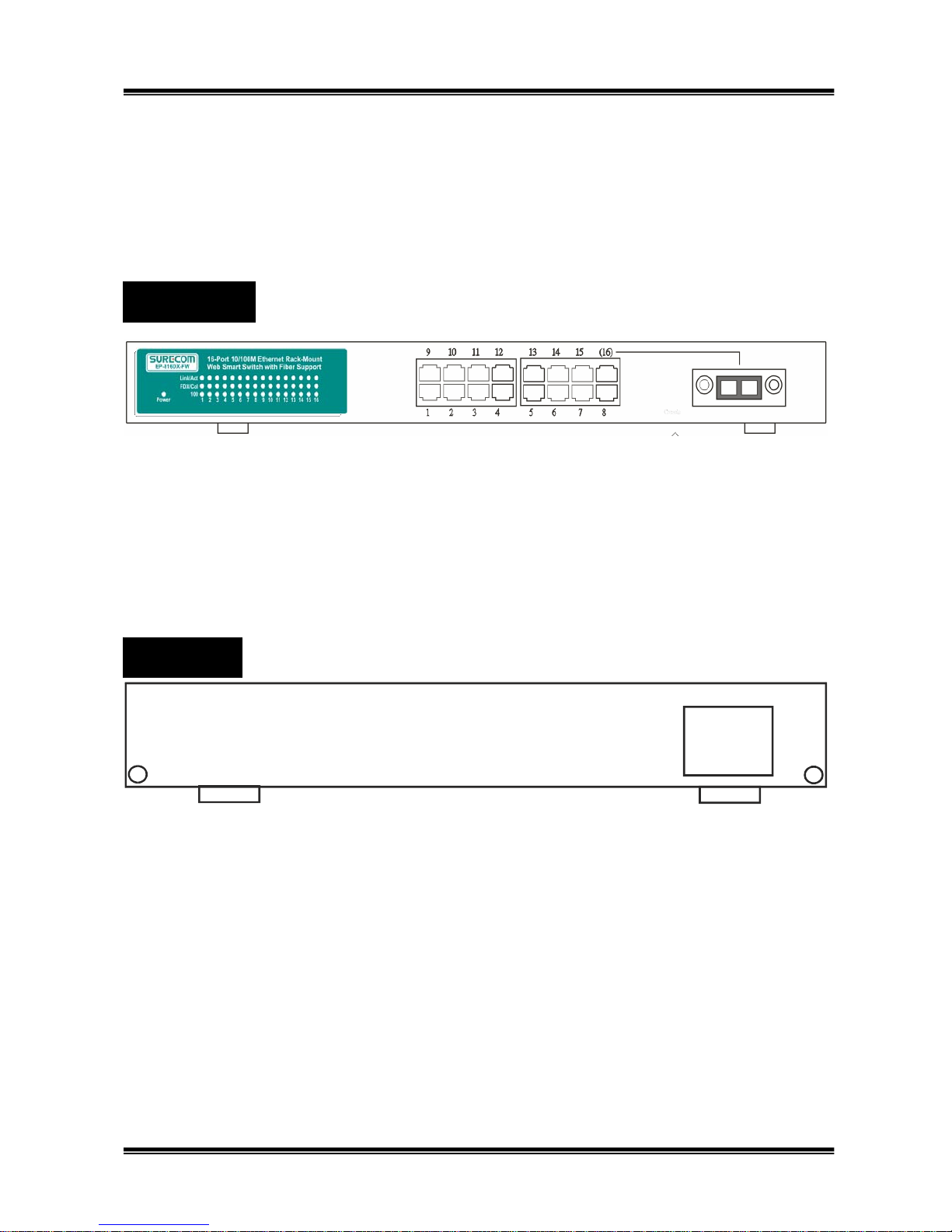
This chapter describes the front panel, LED indicators, and rear panel on the Switch.
2.1 Overview
16*10/100Mbps RJ-45 Ports - Uses these sixteen ports to connect to another Switches or Hubs.
Each portuses auto-negotiation for automatic speed and mode selection.
Fiber Module Slot - Extends the workgroup distance up to 2,000 meters.(Option)
90~264VAC
47~63Hz
Front Panel
Rear Panel
Page 11
11
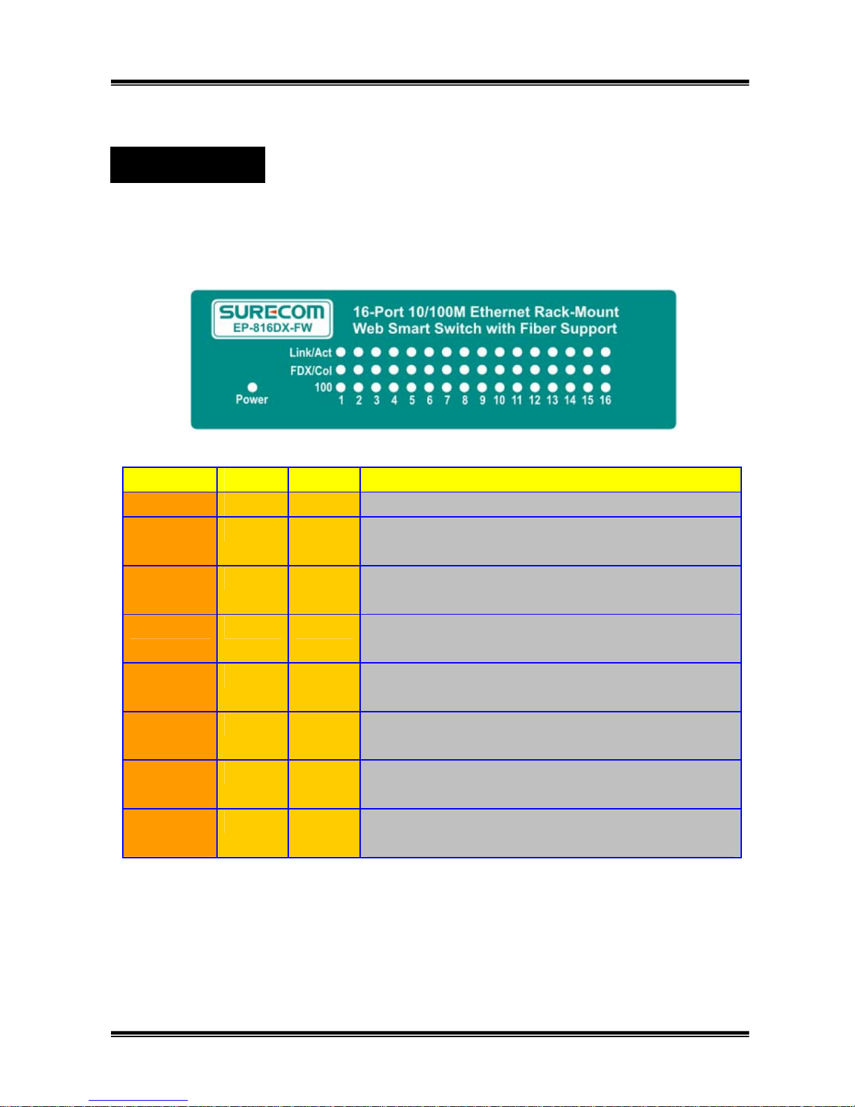
The LED indicators are all located on the front panel which include one Power per device, one
Link/Act., one FDX/Col, and one 100 indicator per port.
LED Color Status Description
Power Green On Lights to indicate the switch is power on.
Link/Act Green On Lights to indicate a functional network link through
the corresponding port with an attached device.
Flashing Blinks to indicate that the router is actively send ing or
receiving data over that port.
FDX/COL Green On Lights to indicate that the connected port is under
Full-Duplex mode.
Off Off to indicate that the connected port is under
Half-Duplex mode.
Flashing Blinks to indicate that the connected port is under
collision status.
100 Green On Lights for any port to indicate that the port is
operating at 100 Mbps.
Off Off to indicate that the port is operating at 10 Mbps
while the network is still operating.
LED Indicators
Page 12
12
2.2 Hardware Connection
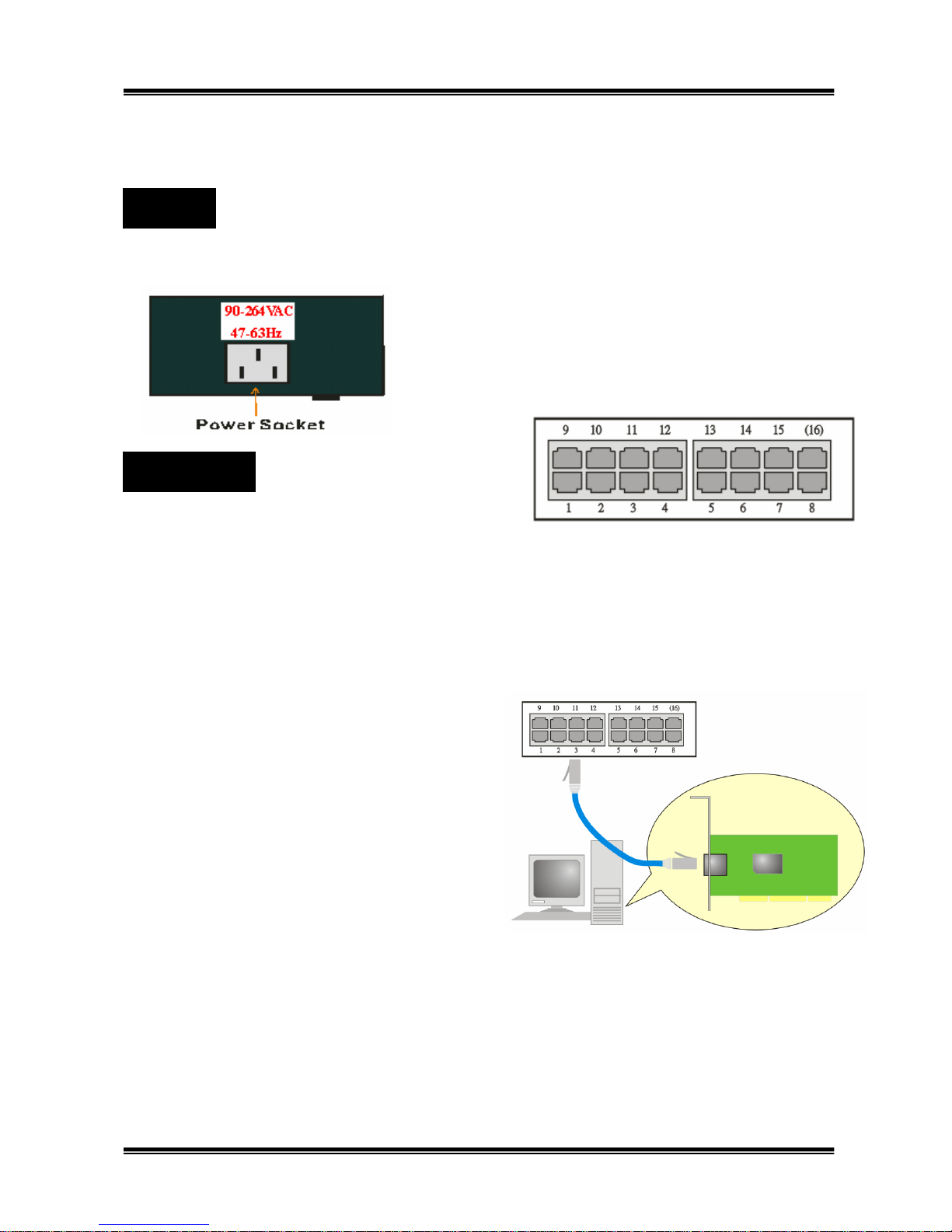
The power receptacle is located on the rear panel of the switch. The standard power receptacle is
for the AC power cord.
The Switch contains 16 10BASE-T / 100BASE-TX
RJ-45 ports.All of these ports support automatic MDI/MDI-X operation, so you can use
straight-through cables for all network connections to PCs or servers, or to other switches or
hubs. Each of these ports also support auto-negotiation, so the optimum transmission mode (half or
full duplex), and data rate (10 or 100 Mbps) can be selected automatically.
See the following section to get more details about connection of RJ-45 ports.
Connecting to PC or Server
You can connect any RJ-45 station port on
the Switch to a PC via twisted-pair cable with
RJ-45 plugs at both ends. Use Category 3, 4 or 5
cable for standard 10Mbps Ethernet connections,
or Category 5 cable for 100Mbps Fast Ethernet
connections.
Make sure you have installed a 10BASE-T or
100BASE-TX network interface card for connecting
a PC to the Switch’s RJ-45 (MDI-X) station ports.
If LEDs don’t light afterpowering on the Switch, check if the LAN card, the cable and connectors
are properly attached to the PC and the Switch. When a attached PC is powered on or reset:
1. The Link/Act LED will light
2. The FDX/Col LED depends on the installed LAN card’s capabilities for the PC and the Switch
connection.
3. The 100M LED will light for 100Mbps connection, otherwise it will be unlighted.
Power
RJ-45 Ports
Page 13
13
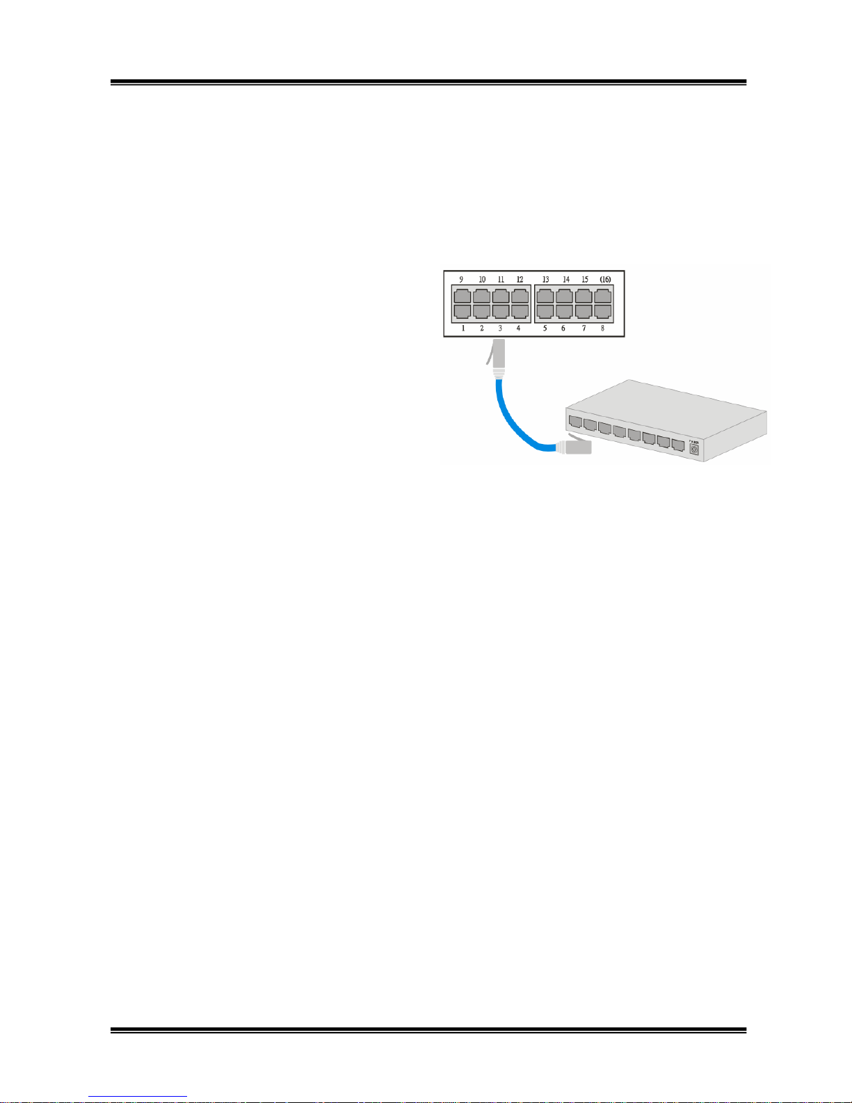
Connecting to Switch or Hub
You can also connect any RJ-45 station port on the Switch to the Uplink port of a Hub or any
port of another switch via straight cable with RJ-45 plugs at both ends.
When a attached 10BASE-T/100BASE-TX Hub is powered on or reset:
(10BASE-T Hub)
The Link/Act LED will light
The FDX/Col LED will be unlighted
The 100 LED will be unlighted
(100BASE-TX Hub)
The Link/Act LED will light
The FDX/Col LED will be unlighted
The 100 LED will light
When a Switch or other devices is switched on:
The Link/Act LED will light
The FDX/Col LED depends on the attached Switch or other devices’ capabilities.
The 100 LED will light for 100Mbps connection, otherwise it will be unlighted.
5
6
7
8
9
1
0
1
1
1
2
1
7
1
8
1
9
2
0
2
1
2
2
2
3
2
4
RJ-45 Ca ble
Page 14

14
3. Using Configuration Menu
The Realtek Remote Control Protocol (RRCP) is a simple control protocol proposed to
enhance the functionalities of this Layer 2 switches by software. The RRCP Management
Application, is a Window-based software package that implements RRCP functions at the
management host side. The RRCP Management Application gives network administrators the
ability to configure and monitor switches like intelligent switches.
Before you getting started, make sure that you meet the following requirements.
1. A computer with an Ethernet netw ork card installed and CD-ROM Drive
2. This CD-ROM with RRCP program
3. Your Windows CD, if your computer is running Windows 98,XP,2000,NT4.0,Service Pack 6
or ME
4. UTP network cable with RJ-45 connector
3.1 Software Installation
WinPcap 3.0 Installation
1. Insert the attached CD-ROM with this switch into PC’s CD-ROM drive.
2 .Select the “WinPcap 3.0” and click “Install”. Then follow the install wizard to finish
installation.
RRCP Installation
1.On the main screen, select “RRCP” and click “Install”. Then follow the install wizard to finish
installation.
2.After installation, there will be a “RRCP Icon” on the desktop.
3.2 Using RRCP
1. Double click the RRCP’s icon or select the “RMT” in the start program menu.
Page 15
15
3.3 Network :
3.3.1 Switch Selection
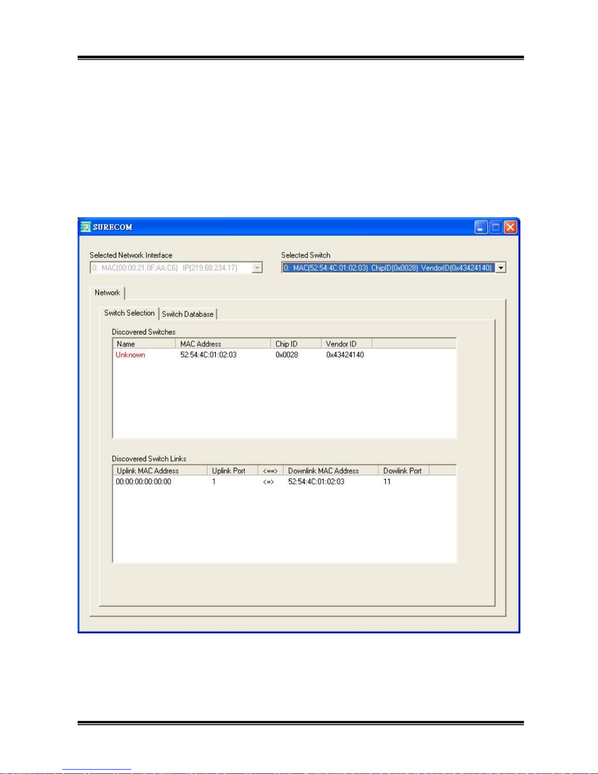
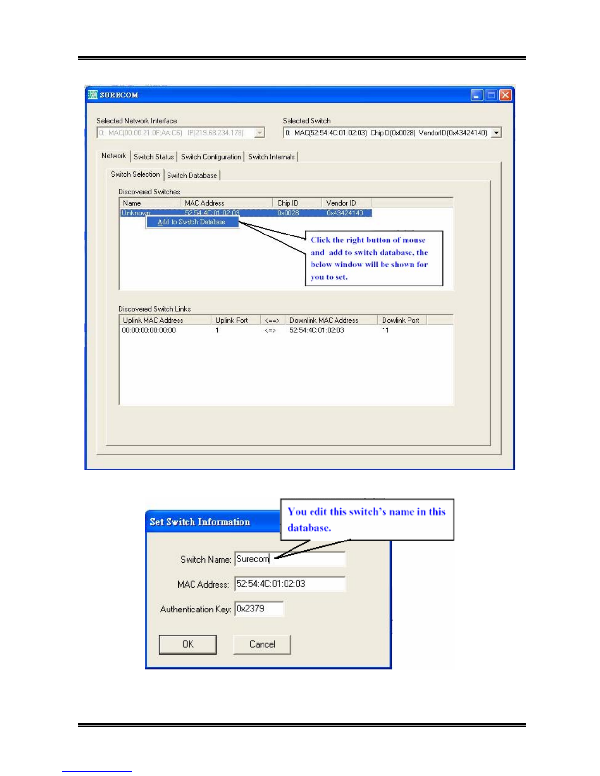
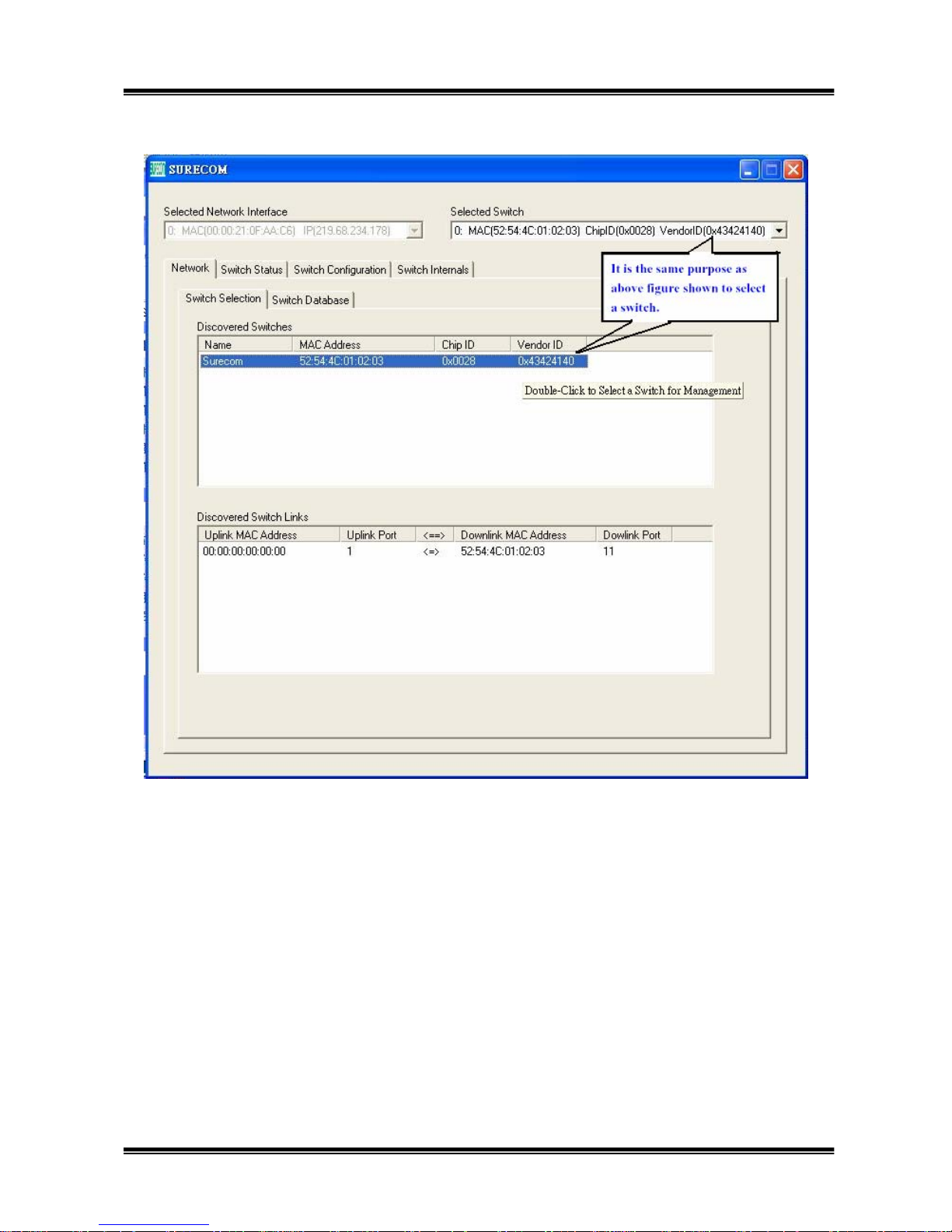
Switch Selection: The all switch that support RRCP function will be shown on this window, and
you have to select one switch that you want to control before you start to manage it.
Page 16
16
Page 17
17
Page 18
18
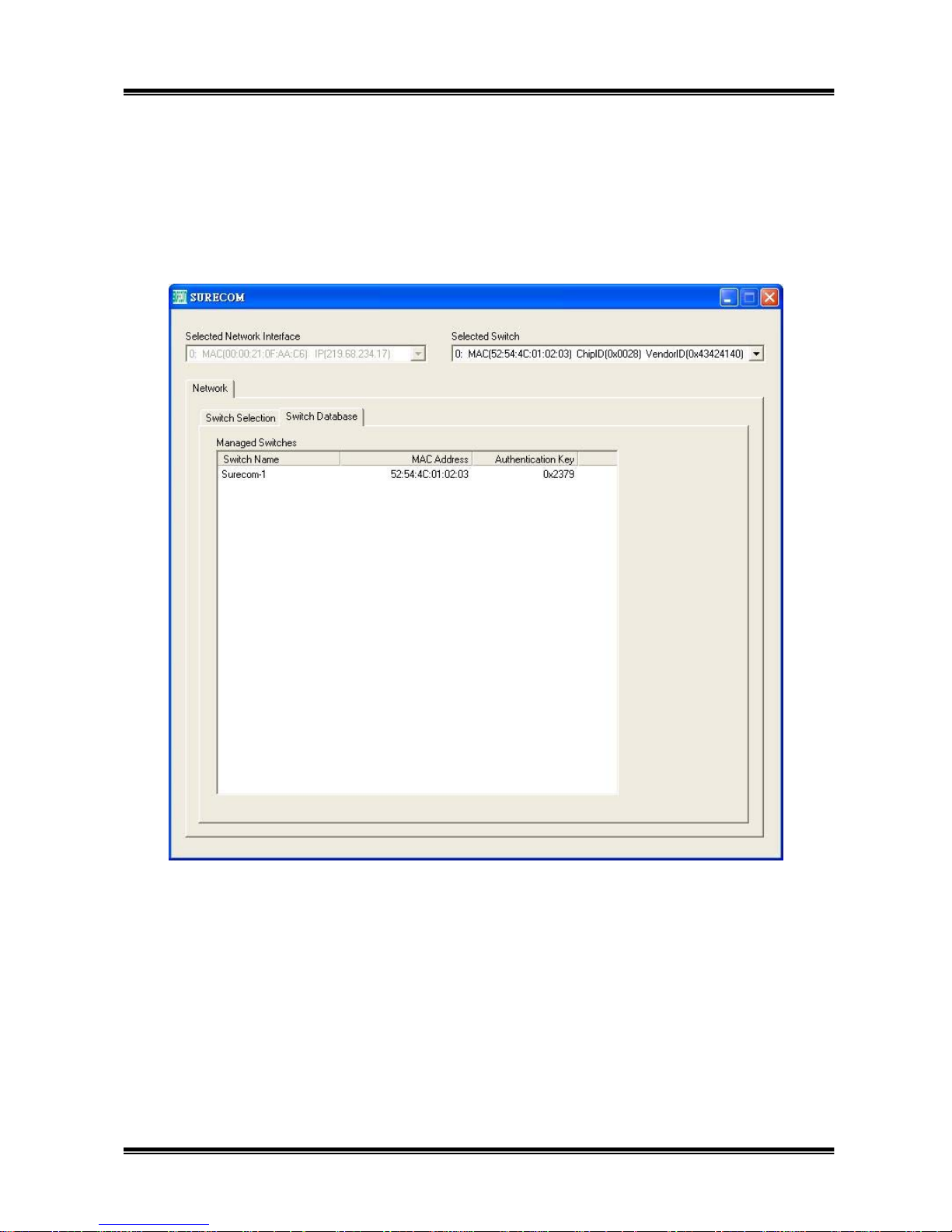
3.3.2
Switch Database
Switch Database: Click the right button to add or edit the switch name
Page 19
19
3.4 Switch Status :
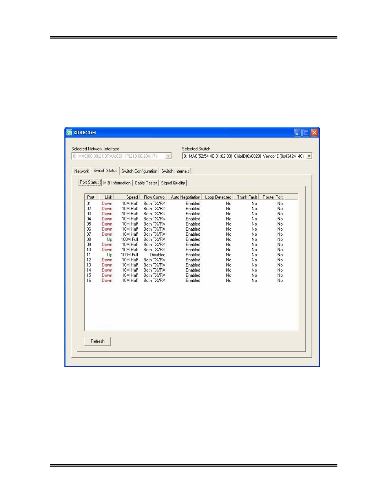
3.4.1 Port Status :
This column shows every port status on the switch. This includes link, speed, flow control, auto
negotiation, loop detect, trunk fault, router port.
Page 20
20
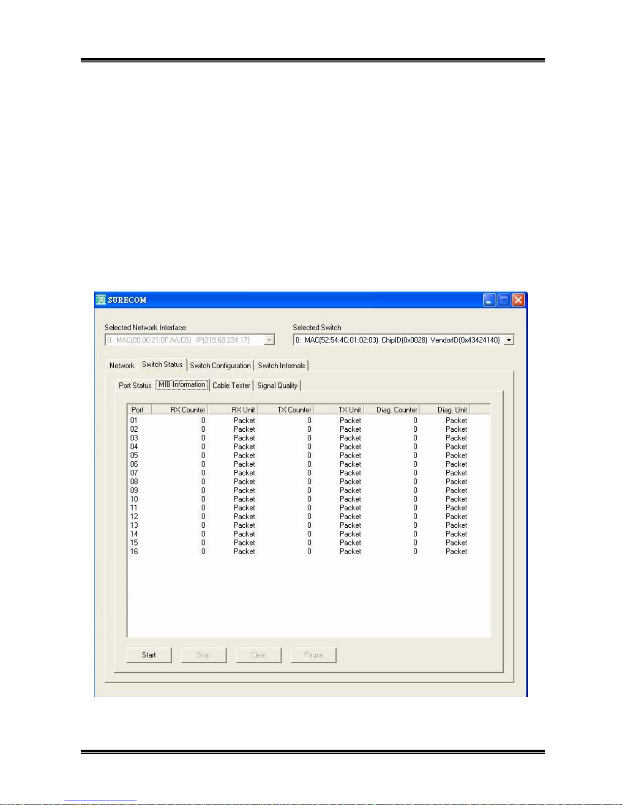
3.4.2 MIB Information:
We can use the MIB Counter function, which the MAC supports to count the packet number
receive in or transmit out the MAC IC. Click the “Start” button, the RMT will show the packet
number that the MAC receive or transmit immediately. Click the “Stop” button, and we can stop the
action of counting the packet number. Click the “Clear” button, and we can clear the number shown
on the window.
Click the ”Pause” button, and we can stop showing the packet number, but this function is not the
same as the ”Stop” button. It will still count but doesn’t show on the window, when you click
“Continue”, the window will show the accumulating packet number in the past time.
Page 21
21
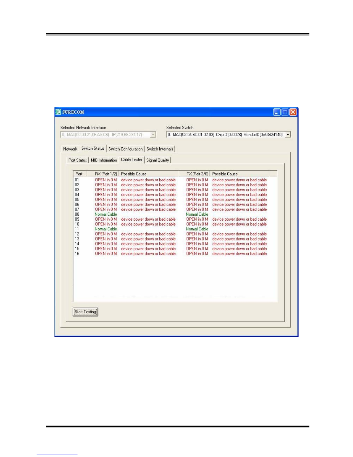
3.4.3 Cable Tester :
Cable tester is a program that can detect the Cable’s status, like short, open, and link on. User can
easily use cable tester function to diagnose cable problem.
You can check whether each port on the switch is connect on the normal station or not, this
Surecom proprietary function can check the TX or RX pair either short or open in what distance
away from the switch.
Page 22
22
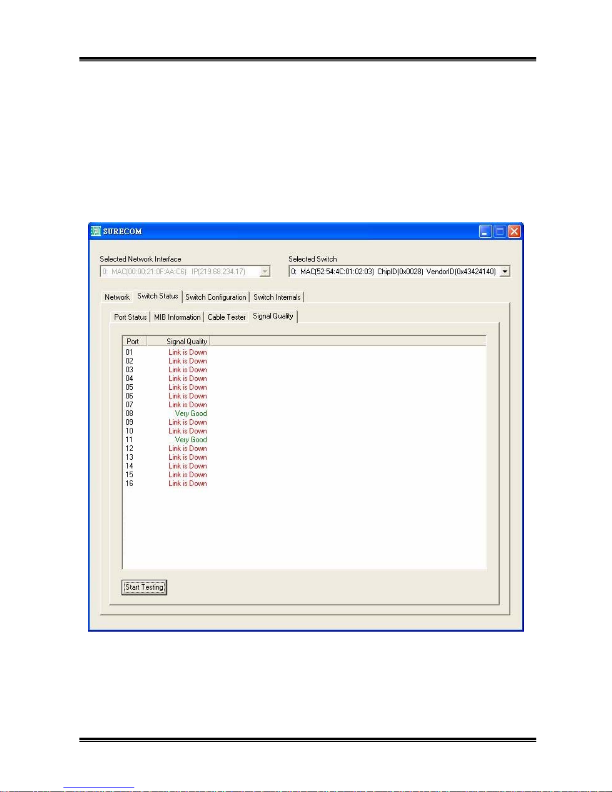
3.4.4 Signal Quality :
This function can determine whether the cable connect on the switch is good or not. The
RTL8208B check the “Signal and Noise Ratio” (SNR) and can determine the cable is “very good”,
“good”, or “bad”.
Page 23

23
3.5 Switch Configuration
In “Switch Configuration” Item including “Global configuration”, “Port Configuration”, “QoS
Configuration”, “VLAN Configuration”, “Port Mirror Configuration” and “Security Configuration”,
an “Apply” button for user to execute. If user don’t click the “apply”, the function will not change
in order to avoid an unintentionally click.
3.5.1 Global Configuration:
Disable/Enable Some Global Configuration:
(1) Broadcast Flow Control.
(2) Multicast Flow Control.
(3) Broadcast Storm Filtering.
(4) Loop Port Detection.
(5) IGMP Snooping.
The “Broadcast Flow Control” and “Multicast Flow Control” are the function for user to transmit
more smoothly when you meet a congested port. The “Broadcast Storm Filtering” can drop
broadcast packets to avoid continuously receive broadcast packets. The “Loop Port Detection” can
detect whether a loop is exist. The “IGMP Snooping” can execute the IGMP function.
Page 24
24
3.5.2 Port Configuration:
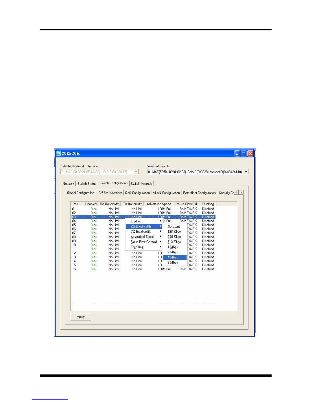
The port configuration includes the configuration of each port.
(1) Enable or disable the port.
(2) RX/TX Bandwidth: Control the port ‘s RX/TX bandwidth, RTL 8324 Provide many kinds of
option to limit the bandwidth of each port: No limit, 128 Kbps, 256Kbps, 512Kbps, 1Mbps,
2Mbps, 4 Mbps, 8 Mbps.
(3) Advertised Speed: 100 or 10 M Speed , Full or Half duplex.
(4) Pause Flow Control: You can choose “No Flow Control” or “Both TX/RX Flow Control” two
options.
(5) Trunking: Enable the trunk port function. Each “Trunking Group” includes four ports as trunk.
Page 25
25
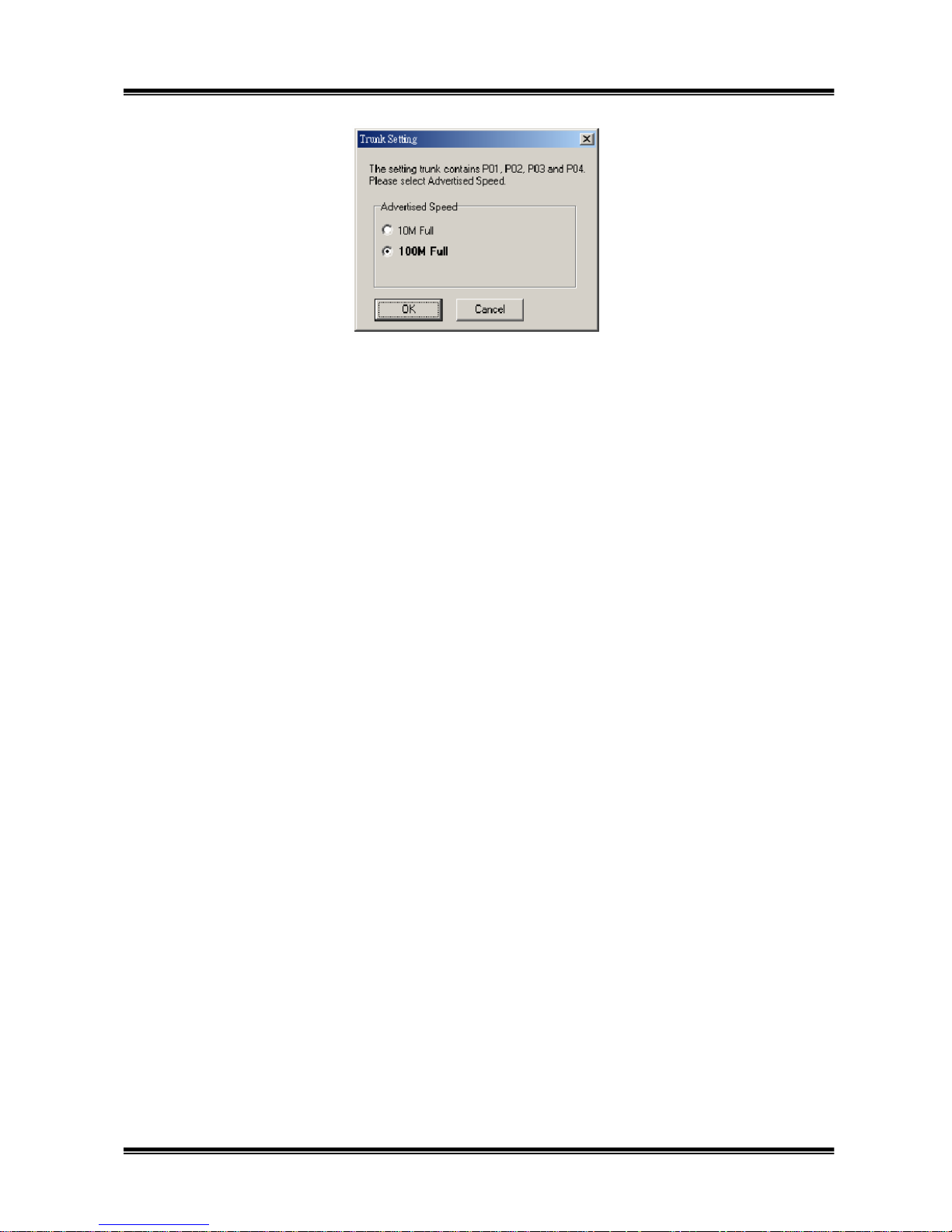
Surecom’s software engineer adds a new function to avoid the user make a wrong setting. In
IEEE 802.3ad standard, it is defined that switch’s trunking must be full duplex and at the same
speed, however, there may be some people make mistakes that setting the trunk but in the wrong
condition. Therefore, we add a choice window while you want to enable a trunk. Whenever you
enable the trunk, RMT will pop up a new window for switch manager to select speed and duplex.
Of course, the network managers still have to take into account the other switch that the trunk ports
connect with.
Page 26
26
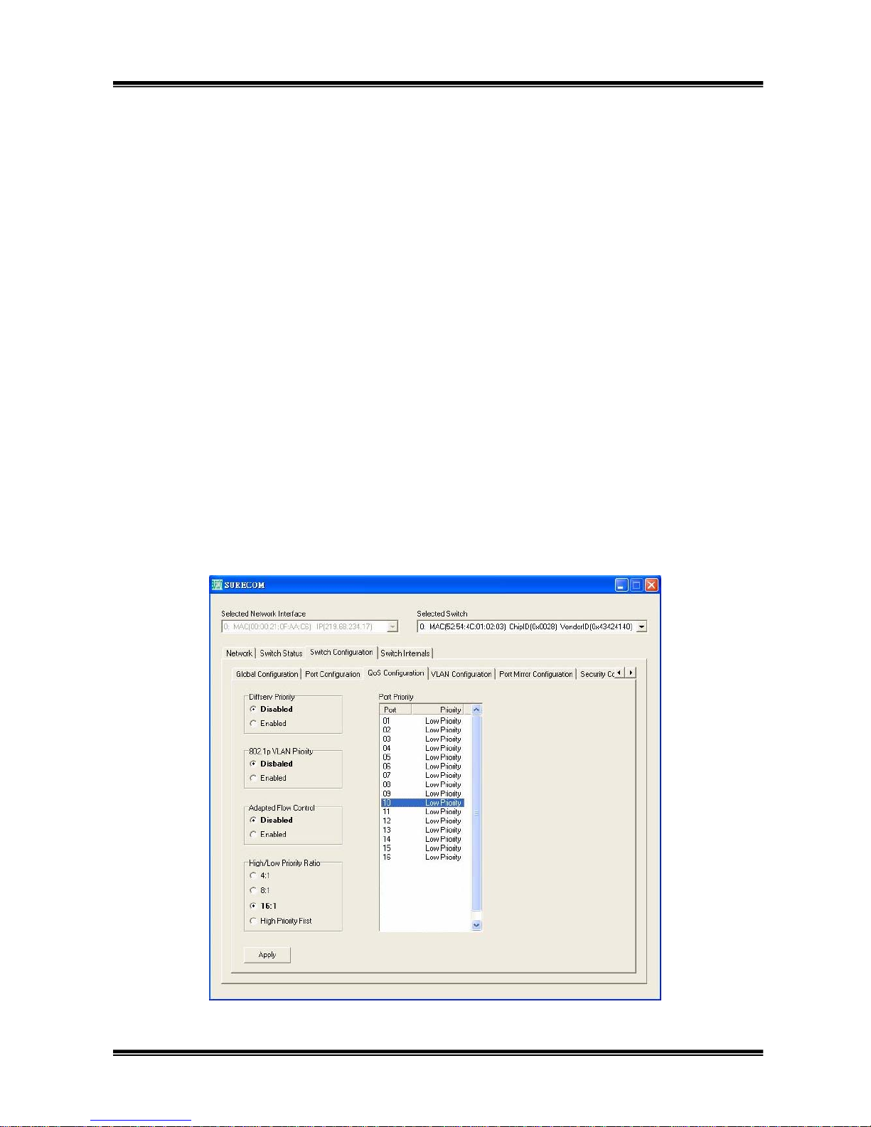
3.5.3 QoS function:
(1) Diffserv Priority:
Enable the feature of the TCP/IP’s TOS/Diffserv(DS) based priority. When the DS field of TOS
octet [0:5] bits are “101110(Expected Forwarding) ; or ”001010”;”010010”,”011010”,”100010”
(Assured Forwarding); or ”11X000”(Network Control),the packet will be a high priority packet,
otherwise the packet will belong to low priority packet.
(2) 802.1p VLAN Priority:
Enable or disable VLAN tag priority, if the packet’s “User priority” is 0~3, it shall be low
priority, the packet will be high priority when its “user priority” is 4~7.
(3) Adapted Flow Control:
Enable the auto turn off flow control function for 1~2 seconds, whenever the port receives a high
priority packet.
(4) High/Low Priority Ratio:
The MAC will transmit the packet from the high priority port and the low priority port as the ratio
of the ratio.
(5) Port Priority:
You can enable each port’s priority, and the packets received from this port will have the higher
priority than those from the port that disable port’s priority.
Page 27

27
3.5.4 VLAN Configuration:
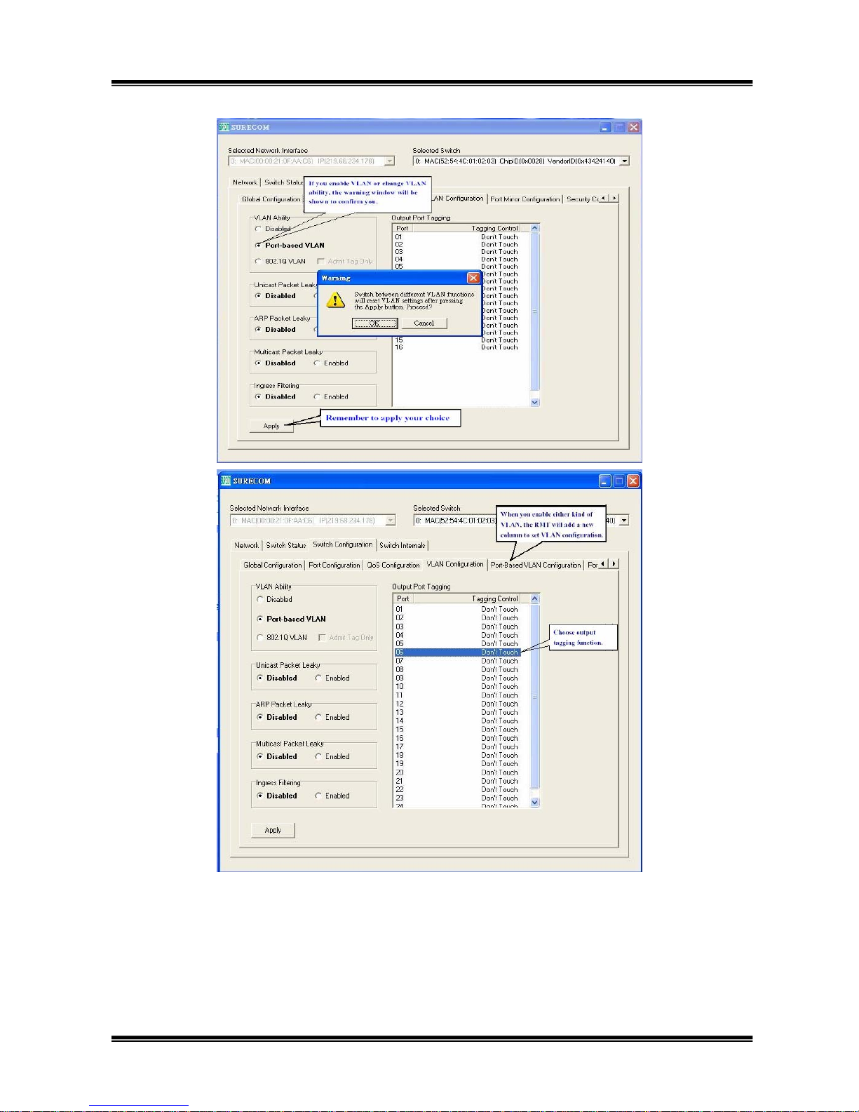
(1) VLAN Ability:
There are three options: Disable VLAN, Port-based VLAN, 802.1Q VLAN. When you change the
option, it will show a window to tell you that Change the VLAN option will reset the setting of
VLAN. When you choose either Port-based VLAN or 802.1Q VLAN, the window will add one
more button for you to set the configuration of VLAN.
(2) Unicast Packet Leaky:
When you enable this function, you will make the unicast packets can be transmit to different
VLAN group.
(3) ARP Packet Leaky:
When you enable this function, you will make the ARP broadcast packets can be transmit to
different VLAN group.
(4) Multicast Packet Leaky:
When you enable this function, the switch will enable IP Multicast packets can be transmit to
different VLAN group.
(5) Ingress Filtering:
When you enable this function, the MAC IC will filter frames received from a port that is not in the
port’s VLAN group.
(6) Output Port tagging:
MAC provides the function to handle the tag of output packet. “Don’t touch”, “Remove tag”,
“Insert tag for high priority frame”, or “Insert tag for all frame”. Users have to notice that ” Insert
tag for high priority frame” and “Insert tag for all frames” only take effect when you enable either
QoS function.
Page 28
28
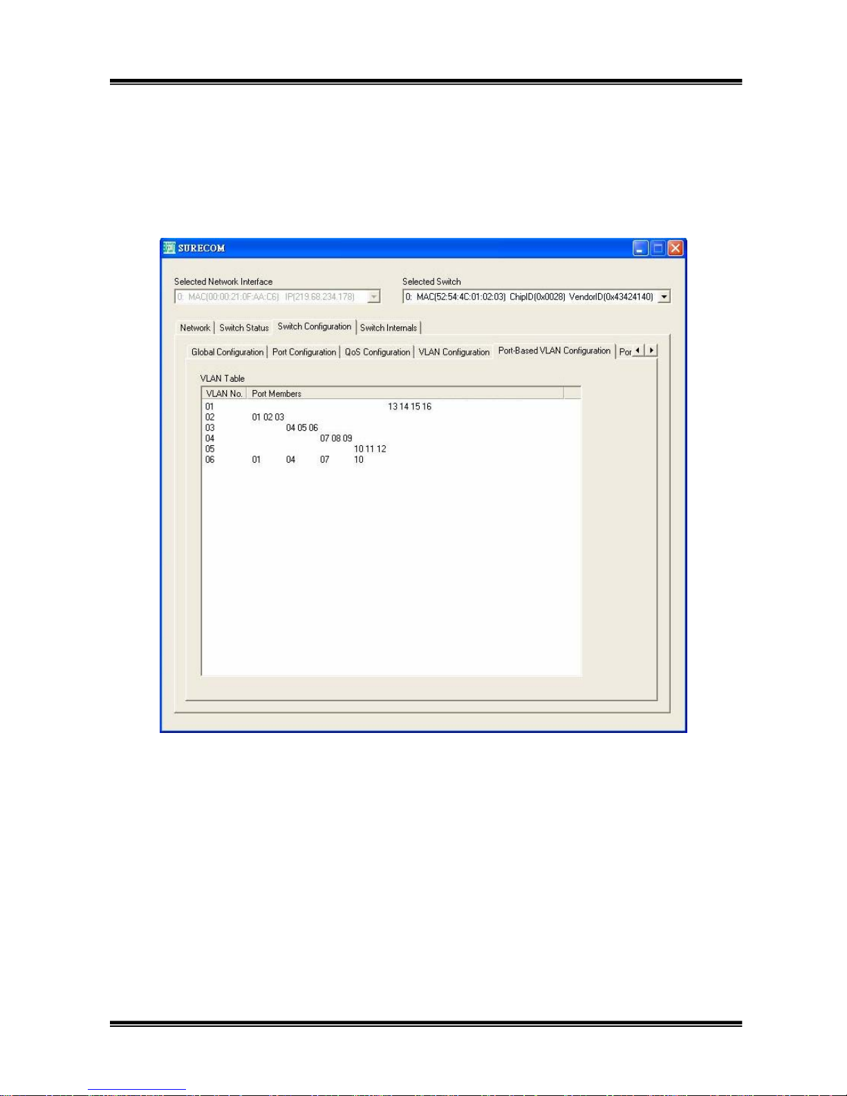
In this example, we have five new VLAN, and the default VLAN. Switch system has six
port-based VLAN. If a packet receive by port 1 and manager don’t enable the unicast leaky function,
and it will be send out only that its destination address is port2~4, port7 and port10. Users have to
notice that “Port-based VLAN” is not the standard VLAN, and it is just for network manager to
Page 29
29
configure the environment more conveniently. Therefore, RMT will add some internal VLAN if
your “Port-based VLAN” setting has configured some overlapping port in different VLAN. Under
this situation, the maximum VLAN you can set is not 31 but depend on how many internal VLAN
have been set.
If we enable the “802.1Q VLAN”, we can decide whether the switch receive untagged frame or
not by enable the “Ingress Filtering” function. Let’s take the below setting in Figure18 for an
example. The RMT 802.1Q VLAN follows the IEEE 802.1Q standard. If we enable this VLAN and
configure as below, the switch can only transmit out the packet that its VID in the tag fit with the
VID of destination port. If a packet with a VID=2 received by port 1, it can only transmitted out to
port 2~port 4.
If a port receives an untagged packet, the MAC will refer to “Port VLAN Mapping” and decide
whether the packet can forward to its destination port. For example, an untagged packet receives by
port1 will forward only to port9~port12 because the “Port VLAN mapping” is VID=4. In addition,
Page 30
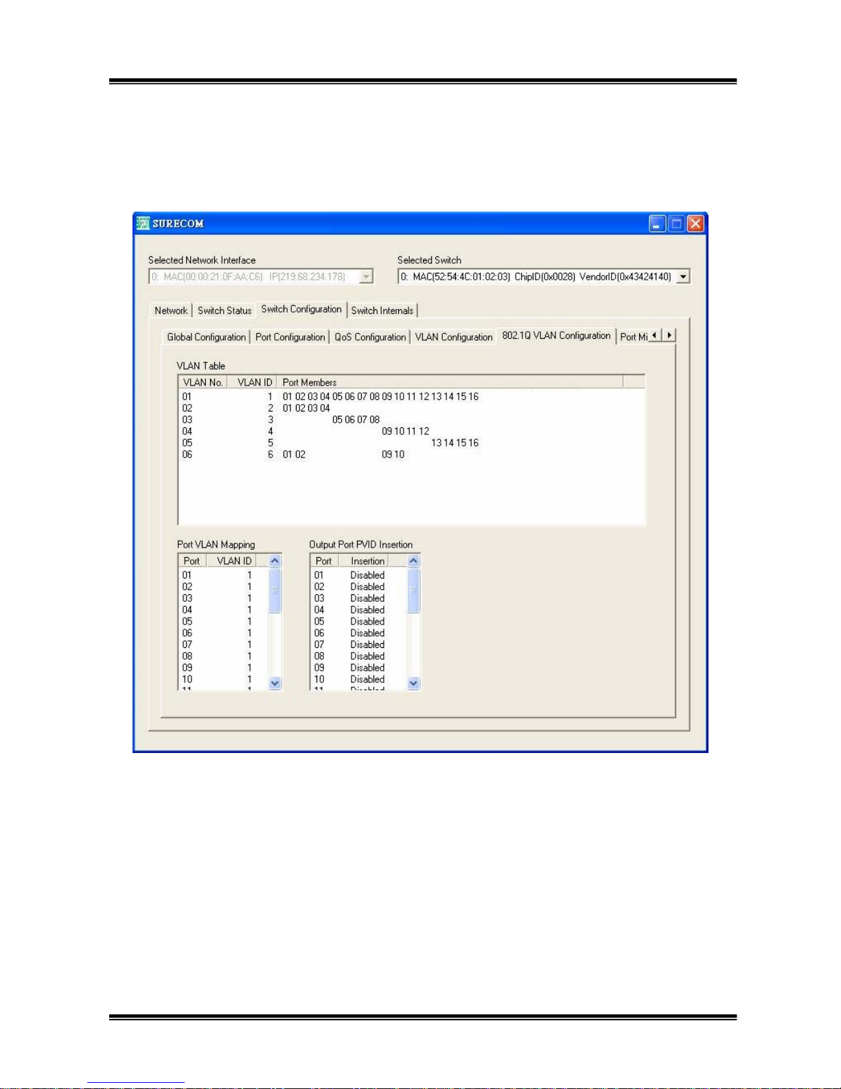
30
“Port VLAN mapping” also map the “Output Port PVID Insertion”, as above example, an untagged
packet with unknown DA receive by port 2 and multicast to port13~port16, MAC will insert a
VID=5 when forward to port14~port16, but packet forward to port13 is still an untagged packet.
Page 31
31
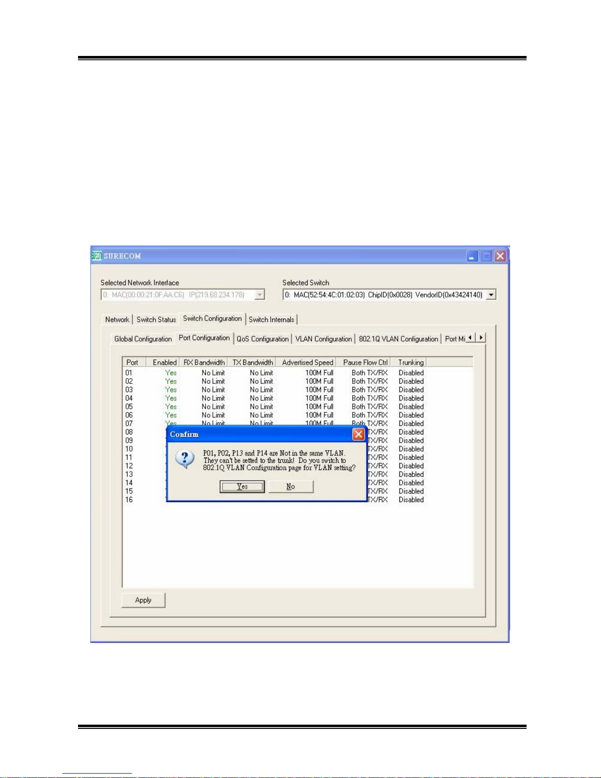
Trunking and VLAN:
It has two methods. After you have set some VLAN, you set the trunk which group don’t belong
to the same VLAN, RMT create a conform window to remind your choice have a fault. If you click
the “Yes” , RMT will change the window to the VLAN setting. You can’t set the trunk successfully
until your trunk settings don’t have collision with VLAN setting. The other way is that you have set
trunk group first, and when you configure the VLAN member, the VLAN will automatically add
the other ports in the same VLAN.
Page 32
32
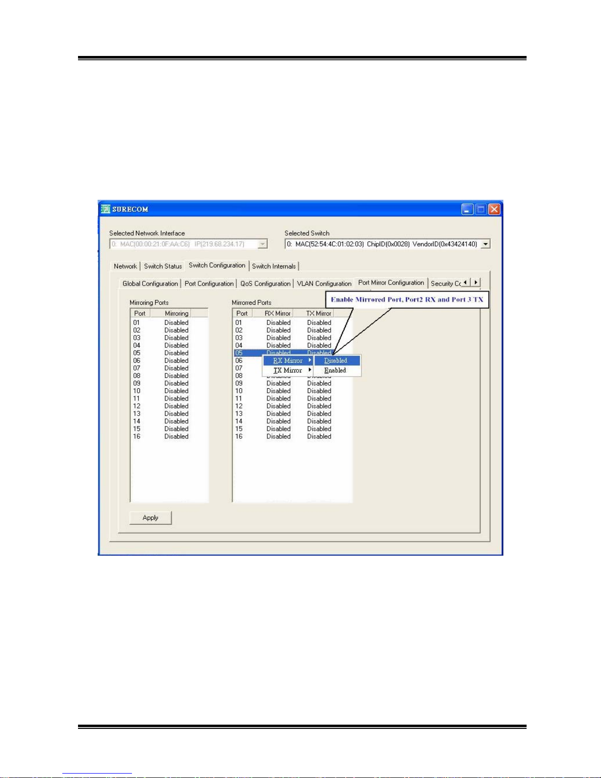
3.5.5 Port Mirror Configuration:
This function can enable the mirror function. Choose the mirroring port, for example, port 1, you
can just click the right button of mouse and enable the port’s mirroring function. Then, choose the
mirrored port, for example, port 2, you can follow the same action as you choose mirroring port, but
at the place of Mirrored port to select which port you want.
Page 33
33
3.5.6 Security configuration:
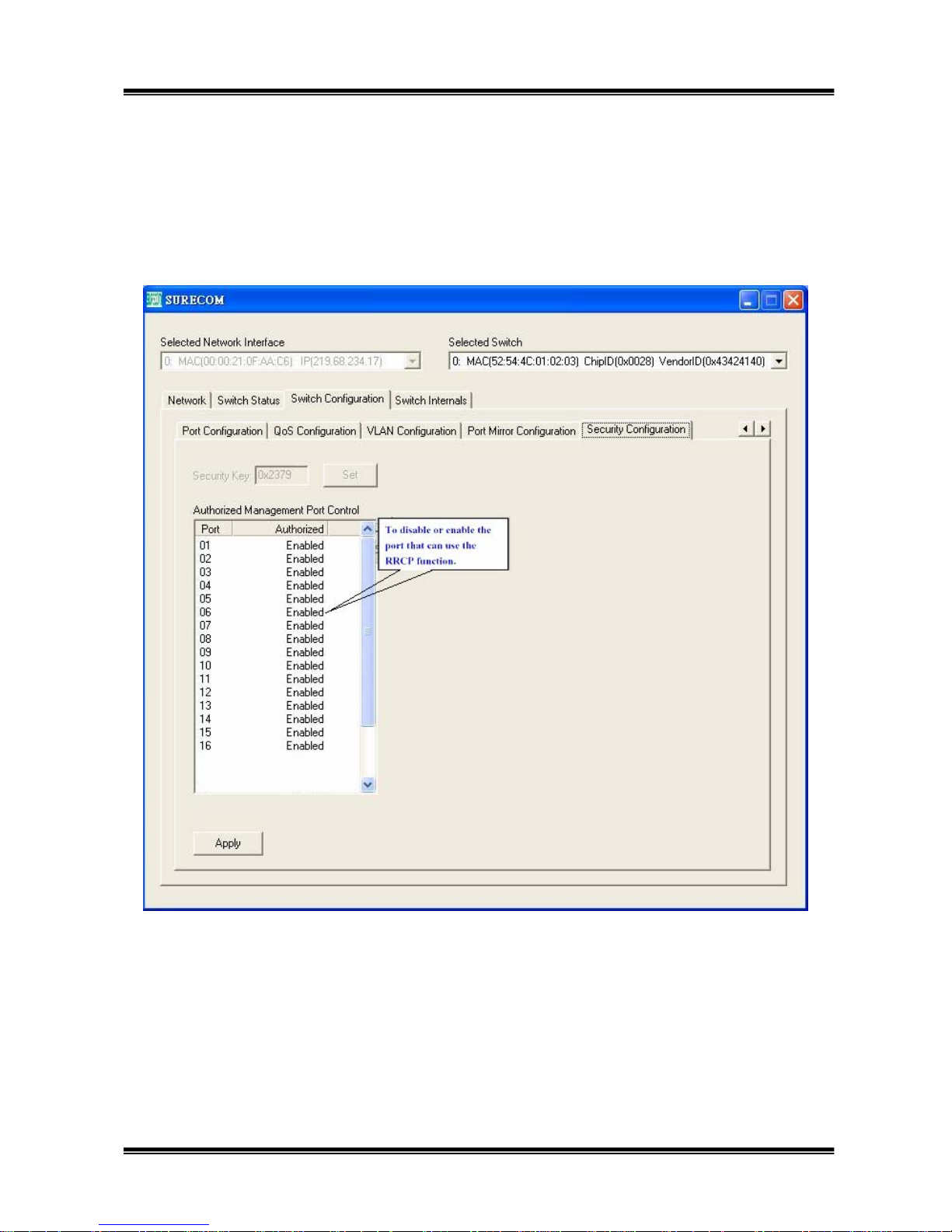
In the third “Security Configuration”, you can choose the ports that can be controlled by RMT, the
ports which you disable the function will not receive RRCP packets. Therefore, you can use this
feature to limit only some users can control the switch by RMT.
Page 34
34
3.6 Switch Internals :
3.6.1
Load Factory Default Configuration
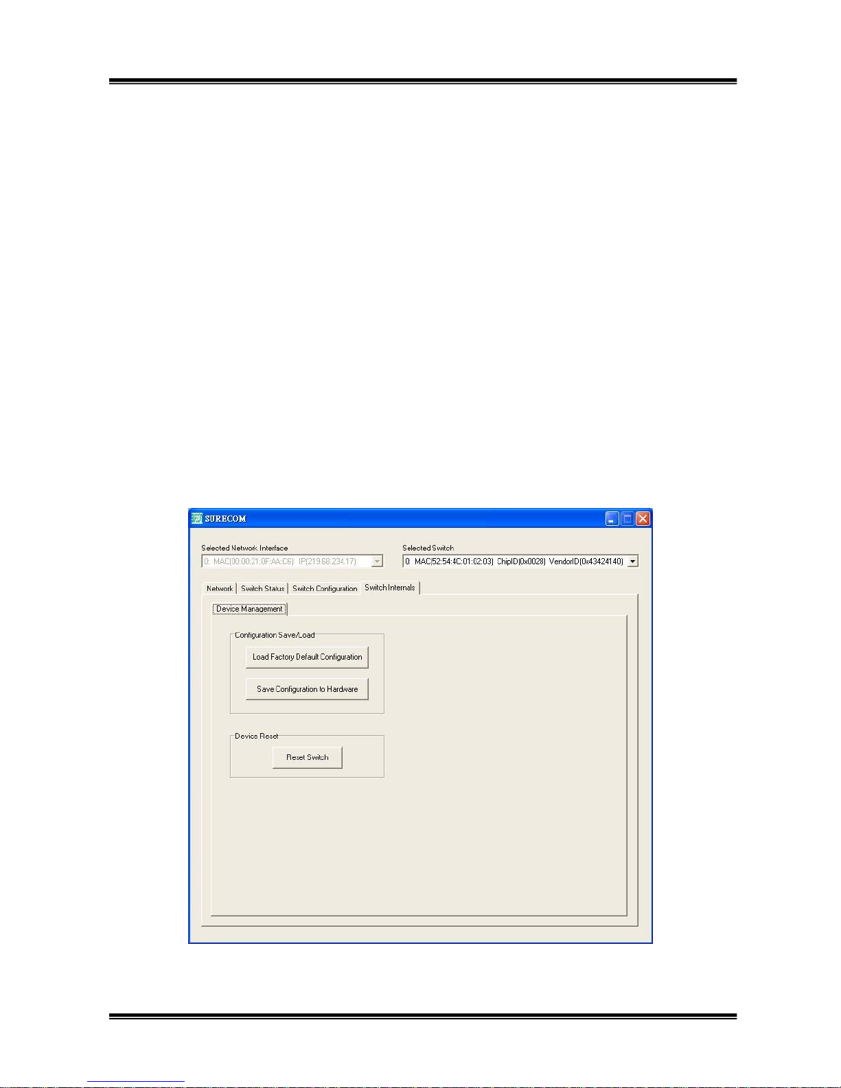
Click the “Load Factory Default Configuration” button, and you can load the default configuration,
which is saved in the Switch hardware (EEPROM). The “Factory Default Configuration” means the
configuration that saved in Switch hardware (EEPROM) when they produce by the factory, and will
not be changed under normal operation.
Note: The Load Factory Default function will not save the “Factory Default” into hardware,
therefore, we suggest that you save configuration after you load factory default.
3.6.2 Save Configuration to Hardware
Click the “Save Configuration to Hardware” button, and you can save the configuration that you
now set in this program.
3.6.3 Reset Switch
Click the “Reset Switch” button, and you can reset the switch as if you push the Reset button or
switch device power off then on.
Page 35

35
2-Year Limited Warranty
Subject to the terms and conditions set forth herein, SURECOM provides this
Limited warranty for its product only to the person or entity that originally
purchased the product from SURECOM or its authorized reseller or distributor.
SURECOM warrants that the hardware portion of the SURECOM products
described below will be free from material defects in workmanship and
materials from the date of original retail purchase of the product, for the period
set forth below applicable to the product type (warranty Period, except as
otherwise stated herein.
2-Year Limited Warranty for the Product(s) is defined as follows:
*Hardware (excluding power supplies and fans) two (2) Year
*Power supplies, fans, and cables are covered by a standard one-year warranty from date of purchase.
*Spare parts and spare kits Ninety (90) days
*Software portion of the product (Software- Ninety (90) days)
 Loading...