

Page 1

16-Port 100/10M N-Way
Rack-Mount Smart Switch Hub
Users Manual
EP-816DX-AS
www.surecom.com.tw
#471816DXAS00
www.surecom-net.com
Page 2
FCC Statement
This equipment can generate, use and radiate radio frequency energy and, if not
installed and used in accordance with the instructions in this manual, may cause
interference to radio communications. This equipment has been tested and found to
comply with the limits for a Class A computing device pursuant to Part 15 of the FCC
rules, which are designed to provid reasonable protection against radio interference
when operated in a commercial environment. Operation of this equipment in a
residential area is likely to cause interference, in which case the user, at his own
expense, will be required to take whatever measures are necessary to correct the
interference.
CE Declaration of Conformity
This is a Class A product. In a domestic environment product may cause radio
interference in which case the user may be required to take adequate measures.
Trademarks
All other brands and product names may be registered trademarks or trademarks of
their respective holders.
Table of Contents
Chapter 1 Introduction
Performance Hightlights
Key Features
Package Contents
Chapter 2 Hardware
Front Panel
LED Indicators
Rear Panel
Chapter 3 Network Connections
Switch to PC
Switch to Hub
Hub without Uplink (MDI) Port
Switch to Switch (Other Devices)
Chapter 4 Console Management Setup
Getting Started
Console Program
Hyper Terminal Setup
Chapter 5 The Smart Switch Setup
Getting Started
Main Menu
Port Configuration Menu
Port Trunking Menu
Trunk Port Setup
VLAN Setup Menu
VLAN Group Setup
Factory Default
Appendix A Technical Specifications
Appendix B Cable Requirements
1-1
1-2
1-3
1-3
2-1
2-1
2-2
2-3
3-1
3-1
3-2
3-3
3-4
4-1
4-1
4-1
4-2
5-1
5-1
5-1
5-2
5-4
5-6
5-8
5-9
5-12
A-1
B-1
i
Page 3
1-1
List of Figures
ii
1
Figure 2-1 Front Panel
Figure 2-2 LED Indicators
Figure 2-3 Rear Panel
Figure 3-1 PC or Workstation Connection
Figure 3-2 10BASE-T or 100BASE-TX Hub Connection
Figure 3-3 Connecting to a Hub without Uplink Port
Figure 3-4 Switch to Switch Connection
Figure 4-1 PC to the Smart Switch Connection
Figure 4-2 Terminal Program
Figure 4-3 Hypertrm.exe Icon
Figure 4-4 New Connection Screen
Figure 4-5 Selecting a Com Port
Figure 4-6 COM2 Properties Setting
Figure 4-7 Select Properties Item
Figure 4-8 Emulation Setup
Figure 5-1 Main Menu
Figure 5-2 Port Configuration Menu
Figure 5-3 Specified Port Configuration
Figure 5-4 Port Trunking Setup Menu
Figure 5-5 Trunk Setup Screen
Figure 5-6 Trunk 1 Setup-1
Figure 5-7 Trunk Setup-2
Figure 5-8 Main Menu
Figure 5-9 VLAN Setup Menu
Figure5-10 VLAN Group Setup Menu
Figure 5-11 Delete Port 3 from Group 1
Figure 5-12 VLAN Group Setup
Figure 5-13 VLAN Group Setup
Figure 5-14 Add Port 3 and Port 4 to Gorup 2
Figure 5-15 Group 2 Setup Finished
Figure 5-16 Factory Default Setup
Fiber Slide-in Port
The 16-Port N-Way Rack-Mount Smart Switch Hub has a fiber slide-in port. With
fiber the workgroup distance could be extended to 2,000 meters and solve the distance
limit.
Full/Half-Duplex and Easy Expansion
Store-and-Forward Scheme
The 16-Port N-way Rack-Mount Smart Switch Hub uses store-and forward
switching to ensure all error packets will be filtered and maintain maximum data
integrity, even under heavy loading.
1. Introduction
2-1
2-2
2-3
3-1
3-2
3-3
3-4
4-1
4-2
4-2
4-3
4-3
4-4
4-4
4-5
5-1
5-2
5-3
5-4
5-6
5-7
5-7
5-8
5-9
5-9
5-10
5-11
5-11
5-11
5-12
5-12
○○○○○○○○○○○○○○○○○○○○○○○○○○○○○○○○○○○○○○○○○○○○
The 16-Port N-Way Rack-Mount Smart Switch Hub is the lastest design in its
N-Way Switches series for easy installation and high-performance in an environment
where traffic on the network and the number of users increase continuously. What makes
the 16-Port N-Way Rack-Mount Smart Switch Hub stand out from the crowd is
its built-in VLAN and Trunk configuration. With VLAN, stations on different
network segments can be grouped into the same LAN segment. The goal of
VLANs is to allow for complete mobility of workstation placement, yet keeping
broadcast traffic to a minimum. When port of a VLAN, the port will only
communicate with other ports in the VLAN. This offers a high degree of
security within the network. With Trunk, the backbone bandwidth can be
increased to advance the network performance by easing and smoothing traffic
load at peak hours. Small businesses and corporate branch offices can take full
advantage of 100Mbps Fast Ethernet performance and preserve existing desktop
investment with no changes required to PCs, NICs, cabling, drivers, or PC
configurations.
The 16-Port N-Way Rack -Mount Smart Switch Hub supports both full/half-duplex on
all ports which are able to provide 200Mbps of bandwidth to the connected devices
using auto-negotiation. The N-Way Smart Switch is also expandable by cascading
two or more switches together or connecting any RJ-45 (MDI-X) ports on the switch
to any device such as a workstation or a server.
Page 4
Key Features
1-2
1-3
Conforms to IEEE 802.3 10BASE-T, IEEE 802.3u 100BASE-TX /FX, and IEEE 802.3X
Flow control for full-duplex standards
Supports store-and-forward mode switching
Provides non-blocking sixteen ports full-wire speed access
Back pressure in half-duplex and flow control in full-duplex
Sixteen 100/10Mbps RJ-45 ports
Full and Half-Duplex mode operation on all ports
Supports one Uplink port / Fiber Slide-in port for expansion
Auto-negotiation capability
Source address learning and aging function
Provides 1K MAC address and 2M RAM buffer
LEDs to indicate Power, Fiber Slide-in, Link/Activity, Full-duplex/Collision, and Speed
status
One 16-Port 100/10M N-Way Rack Mount Switch Hub
One Power Cord
One Warranty Card
One pack of screws
Two Mounting Brackets
This User Manual
Note: If any item is damaged or missing, please contact your supplier.
Provides one Fiber Slide-in port for expansion the workgroup distance to 2,000
meters
Provides one Uplink port to cascade two or more switches
Provides Back-pressure in half-duplex and flow control in full-duplex
Store-and-forward switching scheme capability supports rate adaptation and
ensures data integrity
N-way Auto-negotiation on each RJ-45 port. This allows for auto-sensing of speed
(100/10Mbps) and auto-detecting mode (Full-Duplex or Half-Duplex) thereby
providing you with automatic and flexible solutions in your network connections
Auto-polarity detection for correction of incorrect polarity on the received
twisted-pair on each port
Data forwarding rate 148,800 pps per port at 100% of wire-speed
Data filtering rate eliminates all error packets, runts, etc. at 148,800pps per port at
100% of wire-speed
Package Contents
Performance Highlights
Upgrade
This Switch Hub offers you a simple way to increase Ethernet LAN performance at a
very low per-port cost, letting you migrate power users to high-performance switched
ports. Ethernet workgroups can upgrade to Fast Ethernet without needing to
reconfigure the network. It is a 100/10Mbps Fast Ethernet Switch that offers
solutions in accelerating small Ethernet workgroups bandwidth.
Page 5
1. Fiber select Full/Half-Duplex (Piano switch)
This dip switch is for selecting the Full/Half-Duplex in Fiber operation.
2. Fiber Connector
Extend the workgroup distance up to 2,000 meters.
3. Uplink Port
By cascading two or more switches together.
4. RJ-45 Ports
All Sixteen N-Way RJ-45 STP ports come with auto-negotiation and operate at
100/10Mbps for connection to servers and hubs. All ports can be configuratured
for Full/Half-Duplex mode.
Note: The Fiber Connector, Uplink port and the port #1 share with
the same port. Ensure you do not use them at the same time.
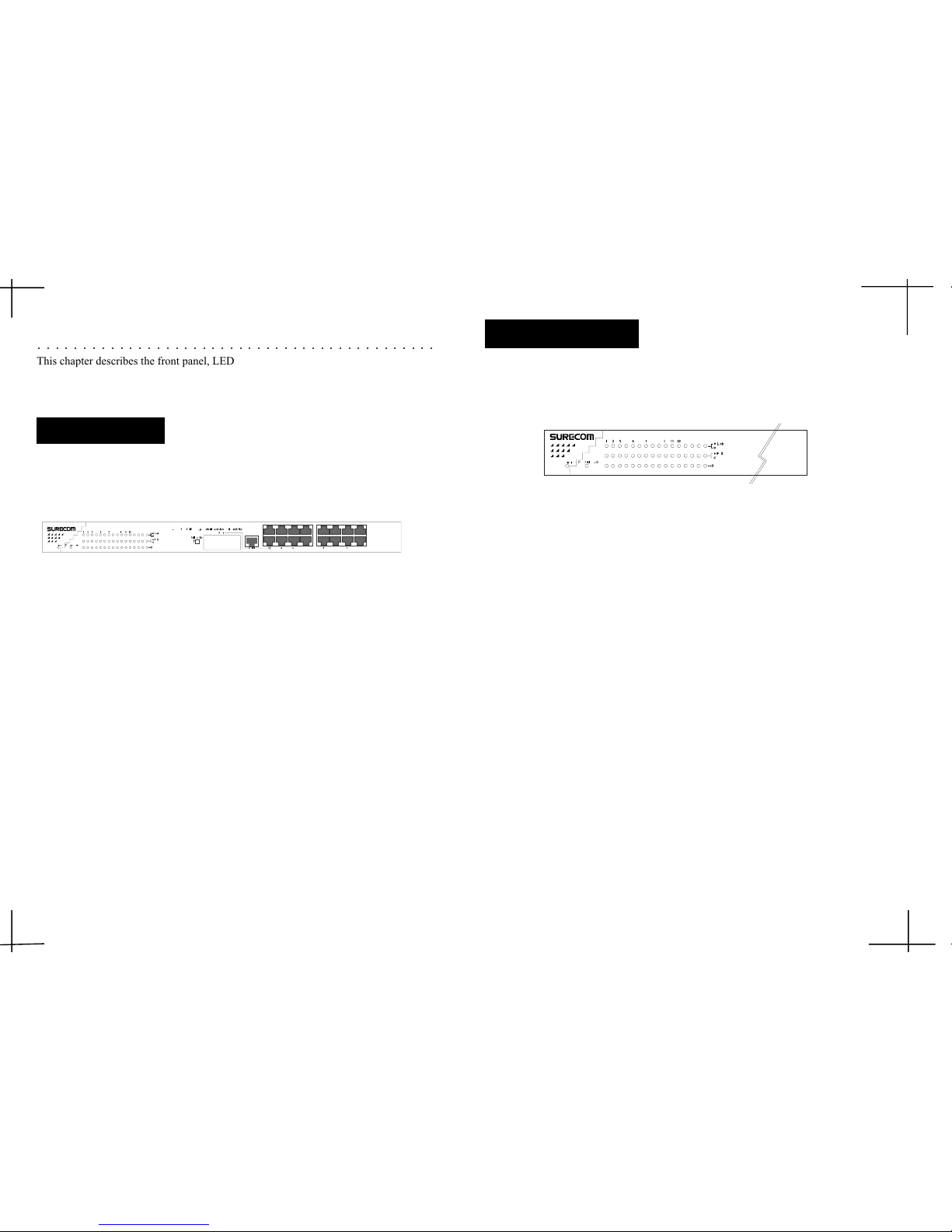
The front panel of the Switch Hub consists of 16 (100/10Mbps MDI-X) ports, 1 Uplink
(MDI) and 1 Fiber slide-in ports.
2. Hardware
○○○○○○○○○○○○○○○○○○○○○○○○○○○○○○○○○○○○○○○○○○○○
This chapter describes the front panel, LED indicators, and rear panel of the Switch
Hub.
Figure 2-1: Front Panel
2-2
The LED indicators of the Switch Hub include Power, Fiber Slide-in, Link/Act (Link
Activity), FDX/Col (Full-Duplex/Collision) and Speed.
Figure 2-2: LED indicators
1. Power
This indicator operates when the Switch Hub is turned on. If this indicator is not
lit, check the AC power connector to ensure proper insertion of the power cord
and that the power switch is turned ON.
2. Fiber Slide-in
This LED lights to indicate the Port#1 is Fiber connector in operation. If this
indicator is not lit, the Port#1 is RJ-45 connector operation.
3. Link/Act
These LED indicators are lighted up green when there is a secure connection (or
link) to a device at any of the ports. The LED indicators blink whenever there is reception or transmission (i.e. Activity/Act) of data occurring at a port.
4. FDX/Col
This LED indicator is green when a respective port is in full-duplex (FDX) mode.
Otherwise, it is OFF for half-duplex (HDX) operations. It blinks when collisions
are occurring on the respective port.
5. Speed
This LED lights when the transmission rate is 100Mbps. It is OFF when the
transmission rate is 10Mbps or no linking.
LED Indicators
2-1
Front Panel
Page 6
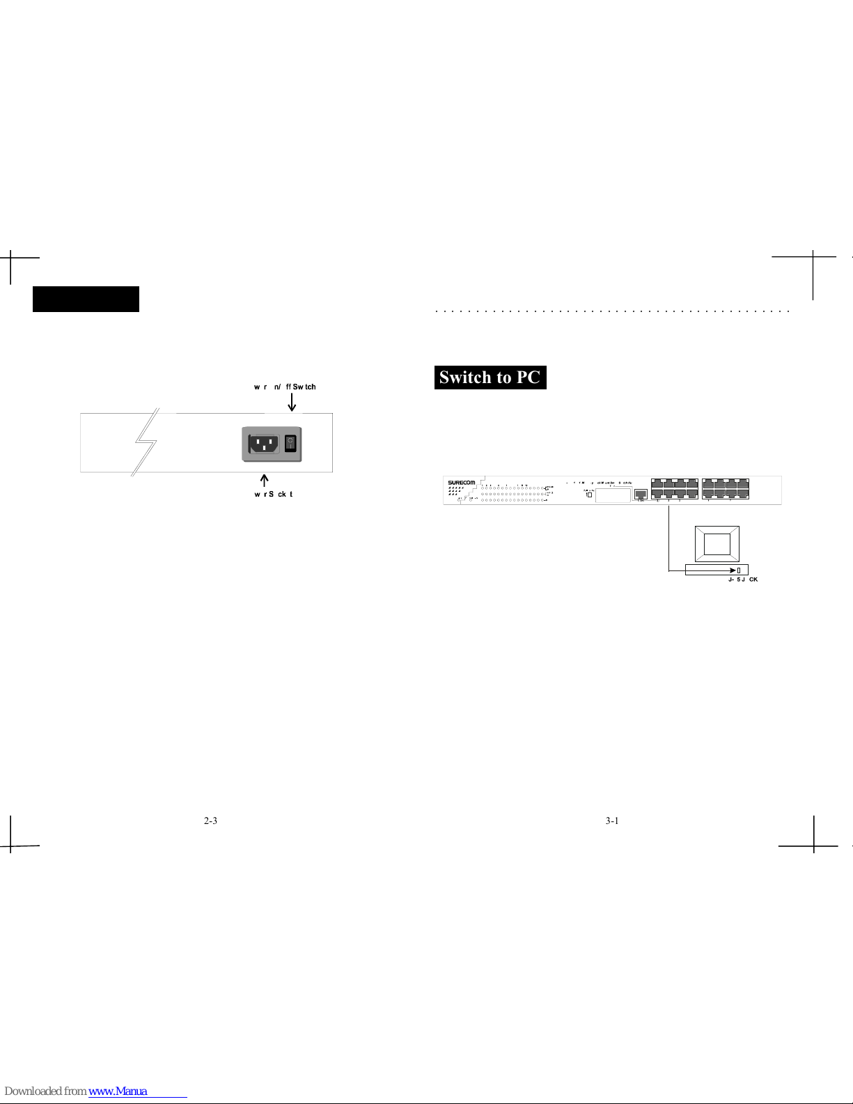
The rear panel consists of an AC power socket and power switch. The system fan for
the Switch Hub is located at the sides of the device.
Figure 2-3: Rear Panel
Rear Panel
1. Power Socket
Plug the power cord into this socket.
2. Power Switch
To turn the power on or off.
2-32-
CHAPTER 3
Network DIY
This chapter describes how to connect this Switch Hub to your Fast Ethernet network.
3. Network Connections
A PC can be connected to the Switch via a twisted-pair Category 3, 4, 5 UTP /STP
straight cable. The PC (equipped with a RJ-45 100/10Mbps jack) should be connected to any
of sixteen ports.
Figure 3-1: PC or Workstation Connection
The LED indicators for PC connection are dependant on the LAN card capabilities. If
LED indicators are not illuminated after making a proper connection, check the PC
LAN card, the cable, Switch conditions and connections.
The following are LED indicator possibilities for a PC to Switch connection:
1. The Link/Act LED indicator illuminates upon hookup.
2. The FDX/Col LED indicator depends upon LAN card capabilities.
3. The 100M LED indicator comes on for a 100 Mbps and stays off for 10Mbps.
○○○○○○○○○○○○○○○○○○○○○○○○○○○○○○○○○○○○○○○○○○○○
2-3 3-1
Switch to PC
Page 7
3-2 3-3
Switch to Hub
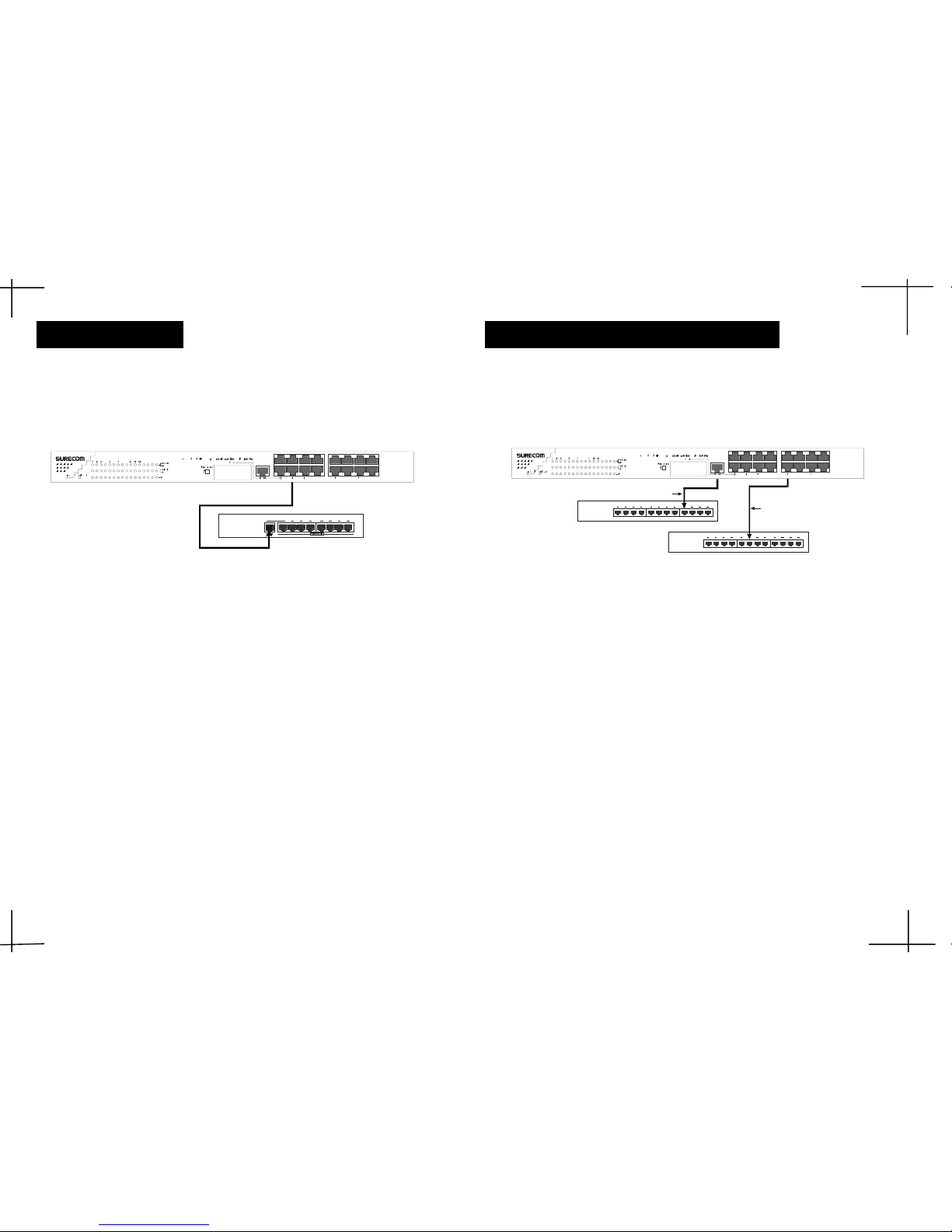
A hub (10BASE-T or 100BASE-TX) can be connected to the Switch via a
twisted-pair Category 3, 4, 5 UTP/STP straight cable. The connection is accomplished from the any port (MDI-X) to uplink port(MDI) of the connected hub.
Figure 3-2: 10BASE-T or 100BASE-TX Hub Connection
10BASE-T Hub
For a 10BASE-T hub, the Switch LED indicators should illuminate the following:
Link/Act indicator is ON.
FDX/Col indicator is OFF.
LED speed indicator is OFF.
100BASE-TX Hub
For a 100BASE-TX hub, the Switch LED indicators should illuminate the following:
Link/Act is ON.
FDX/Col LED indicator is OFF.
LED speed indicator is ON.
Hub without Uplink (MDI) Port
If a hub is not equipped with an uplink (MDI) port, then connection can be made using
either straight cable or crossover cable (see Appendix A, Technical Specifications for cable
requirements).
Figure 3-3: Connecting to a Hub without Uplink Port
Using straight cable
When using straight cable, The connection can be made from the uplink port of the
Switch to any port of the Hub (see figure 3-3).
Using crossover cable
When using crossover cable, the connection can be made from any (Port #1 - 16) port
of the Switch to any port of the Hub (see figure 3-3).
Hub
Page 8
3-4
Switch to Switch (Other Devices)
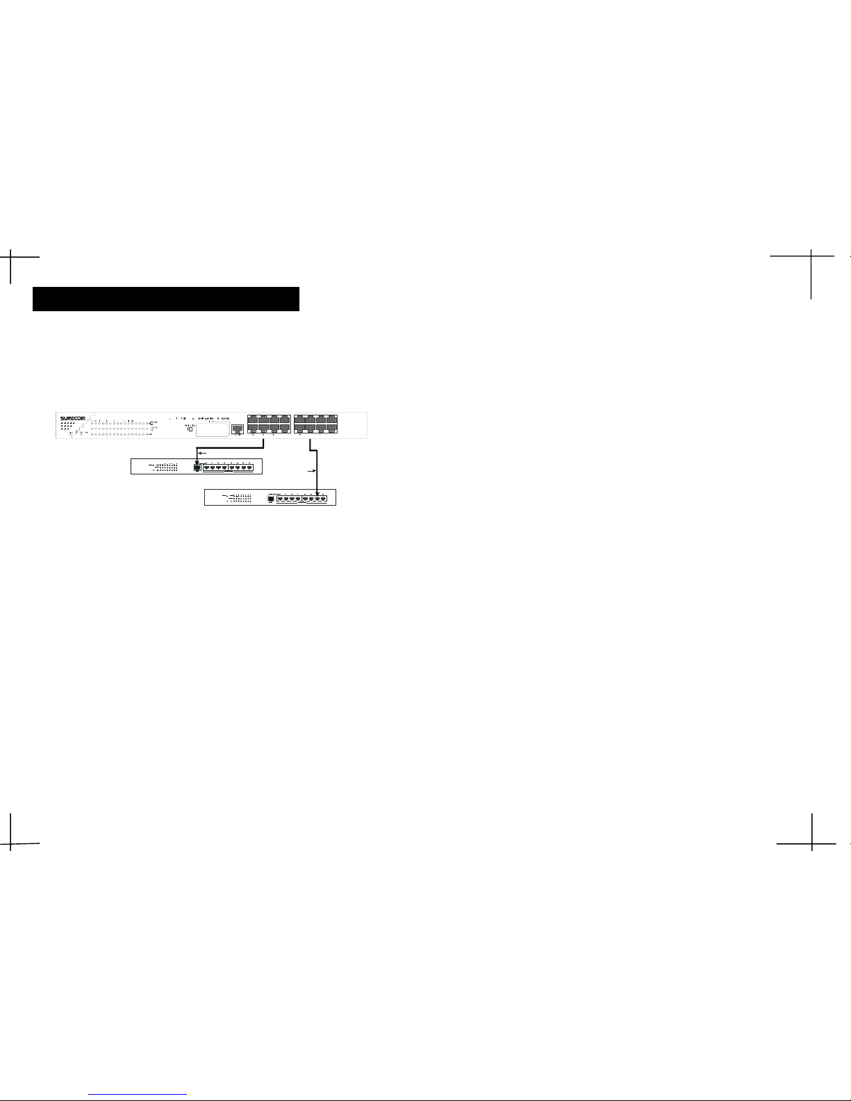
The Switch can be connected to another switch or other devices (routers, bridges, etc.)
via a twisted-pair category 3, 4, 5 UTP/STP straight or crossover cable.
Figure 3-4 Switch to Switch Connection
±µP. 4 - 1
Using straight cable
When using straight cable, this is done from the Uplink port of the Switch (Switch A)
to any of the 10Mbps or 100Mbps (MDI-X) port of the other switch (switch B) or
other devices.
Using crossover cable
When using crossover cable, this is done from any port of the Switch (Switch A) to
any of the 10Mbps or 100Mbps (MDI-X) port of the other switch (switch B) or other
devices (see Figure 3-4).
Switch A LED indicators for the respective connected ports are as follows:
Link/Act is ON.
FDX/Col depends on the connected switch or other device.
100M is ON for 100BASE-T, otherwise OFF.
Page 9
Physical and Environmental
RAM Buffer: Total 2M bytes per device
Filtering Address
Table: 1 K entries per device
Packet Filtering/
Forwarding Rate: Wire speed per port (for 100Mbps&10Mbps)
Dimensions: 44 x 20 x 4.5 cm (LxWxH)
Net Weight: 4.2Kg
Power: Internal Universal Power,
Input:100~240V(47~63Hz); Output:5V/8A
Consumption: 25 watts maximum
DC fans: 1 built-in 40x40 mm fan
Temperature:
Operating: 0 ° ~ 55 °C
Storage: 0 ° ~ 65 °C
Humidity:
Operating: 10% ~ 90%
Storage: 5% ~ 95%
Conformance: FCC Class A, CE Mark Class A
A. Technical Specifications
○○○○○○○○○○○○○○○○○○○○○○○○○○○○○○○○○○○○○○○○○○○○
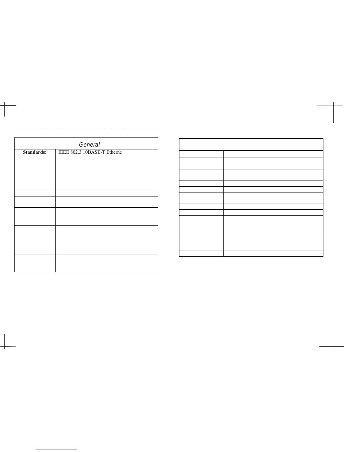
General
Standards: IEEE 802.3 10BASE-T Ethernet
IEEE 802.3u 100BASE-TX/FX Fast Ethernet
ANSI/IEEE Std 802.3 N-way auto-negotiation
IEEE 802.3 Frame types: Transparent
IEEE 802.3 MAC layer frame size: 64-1518 Bytes
IEEE 802.3x flow control for Full-Duplex
Protocol: CSMA/CD
Topology: Star
Transmission
Method: Store-and-Forward
Transfer Rate:
Ethernet: 10M (half-duplex); 20M (full-duplex)
Fast Ethernet: 100M (half-duplex); 200M (full-duplex)
Media:
10BASE-T: UTP Cat. 3,4,5 (Max. cable length100 m);
100BASE-TX: UTP Cat. 5 (Max. cable length 100 m);
100BASE-FX: Multi-mode Fiber cable (Max. cable length
2,000 m)
No. of Ports: 16 100/10Mbps RJ-45 ports
Media Interface
Exchange: MDI RJ-45 shared with Port # 1
A-1 A-2
Page 10
The following shows straight cable and crossover cable connection:
Rx-
Rx+
Tx-
Tx+
Tx+
Tx-
Rx+
Rx-
1
2
3
6
1
2
3
6
Straight Cable
Up lin k ( MDI) P ort on S witch/Hub
RJ-45 port on Adapter
or
Normal RJ-45(MD I-X) Port
on Switch/Hub
Straight cable for Switch (uplink MDI port) to switch/Hub or other
devices connection
B
B
BB
BB
B
--
--
-
22
22
2BBb
Crossover cable for Switch (MDI-X port) to switch/hub or other
network devices (MDI-X port) connection
B-1
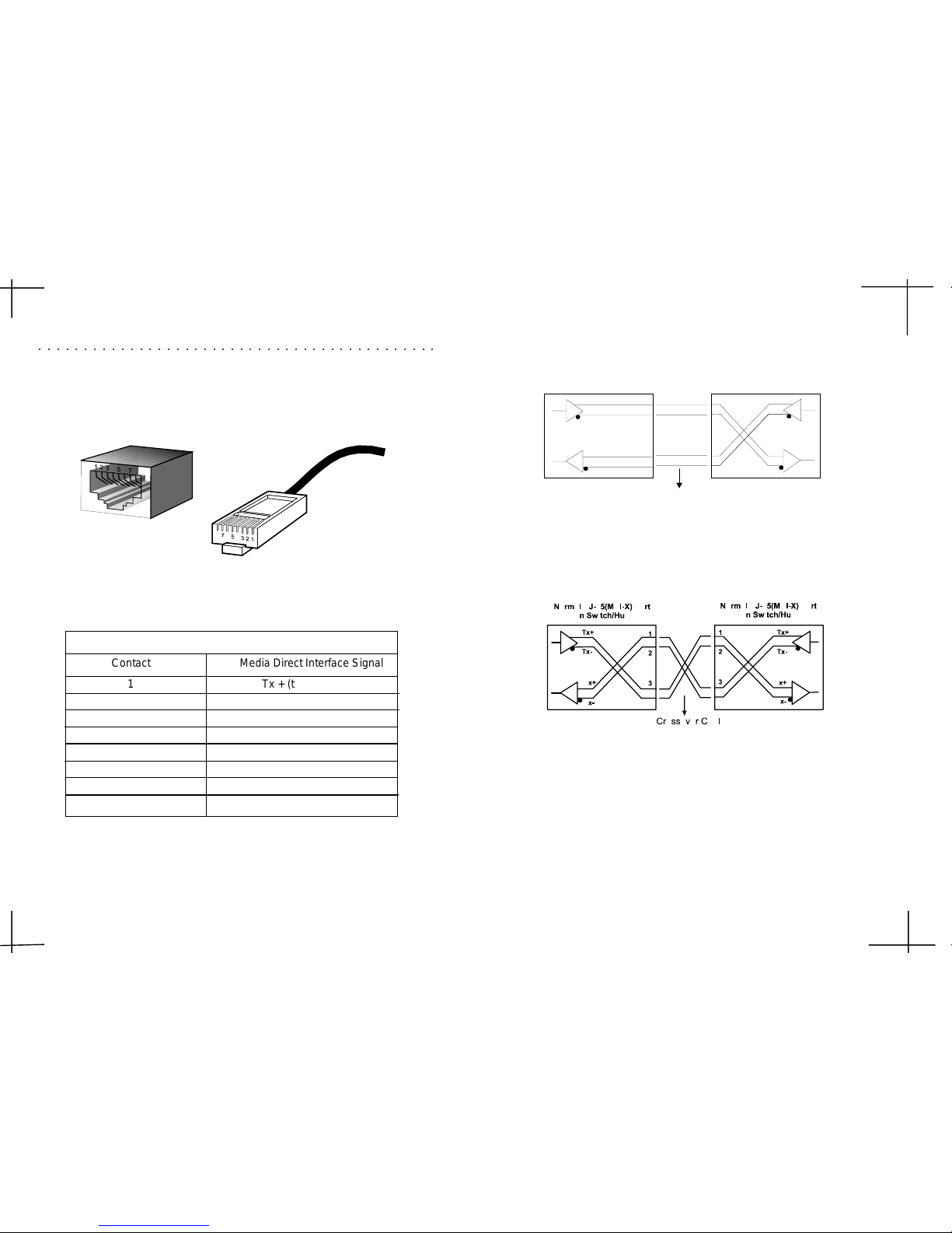
B. Cable Requirements
The following diagram and table show the standard RJ-45 receptacle/connector and
their pin assignments for the switch-to-network interface card connection, and the
straight/crossover cable for the Switch-to-switch/hub/bridge connection.
The standard RJ-45 receptacle/connector
○○○○○○○○○○○○○○○○○○○○○○○○○○○○○○○○○○○○○○○○○○○○
Contact Media Direct Interface Signal
1 Tx + (transmit)
2 Tx - (transmit)
3 Rx + (receive)
4 Not used
5 Not used
6 Rx - (receive)
7 Not used
8 Not used
The standard Category 3 cable, RJ-45 pin assignment
RJ-45 Connector pin assignment
 Loading...