

Page 1

FCC Statement
This equipment can generate, use and radiate radio frequency energy and, if not
installed and used in accordance with the instructions in this manual, may cause
interference to radio communications. This equipment has been tested and found
to comply with the limits for a Class A computing device pursuant to Part 15 of the
FCC rules, which are designed to provide reasonable protection against radio interference when operated in a commercial environment. Operation of this equipment
in a residential area is likely to cause interference, in which case the user, at his
own expense, will be required to take whatever measures are necessary to correct
the interference.
CE Declaration of Conformity
This is a Class A product. In a domestic environment product may cause radio
interference in which case the user may be required to take adequate measures.
Trademarks
All other brands and product names may be registered trademarks or trademarks
of their respective holders.
EP-816CX/DX
/DX-FS
16-Port 10/100M Ethernet Desktop/
Rack Mount Smart Switch
Users Manual
"%&$+,.
www.surecom-net.com
Page 2
1.One 16-Port 10/100M Ethernet Rack-Mount Smart Switch
2.One Power Cord
3.One Users Guide
4.Two Rack Mount Kits (Only for 816DX/DX-FS)
One Pack of Screws (Only for 816CX)
Note: If any item is damaged or missing, please contact your supplier.
Package Contents
Hardware
Following describes the front panel, LED indicators, and rear panel of the
Switch.
Front Panel
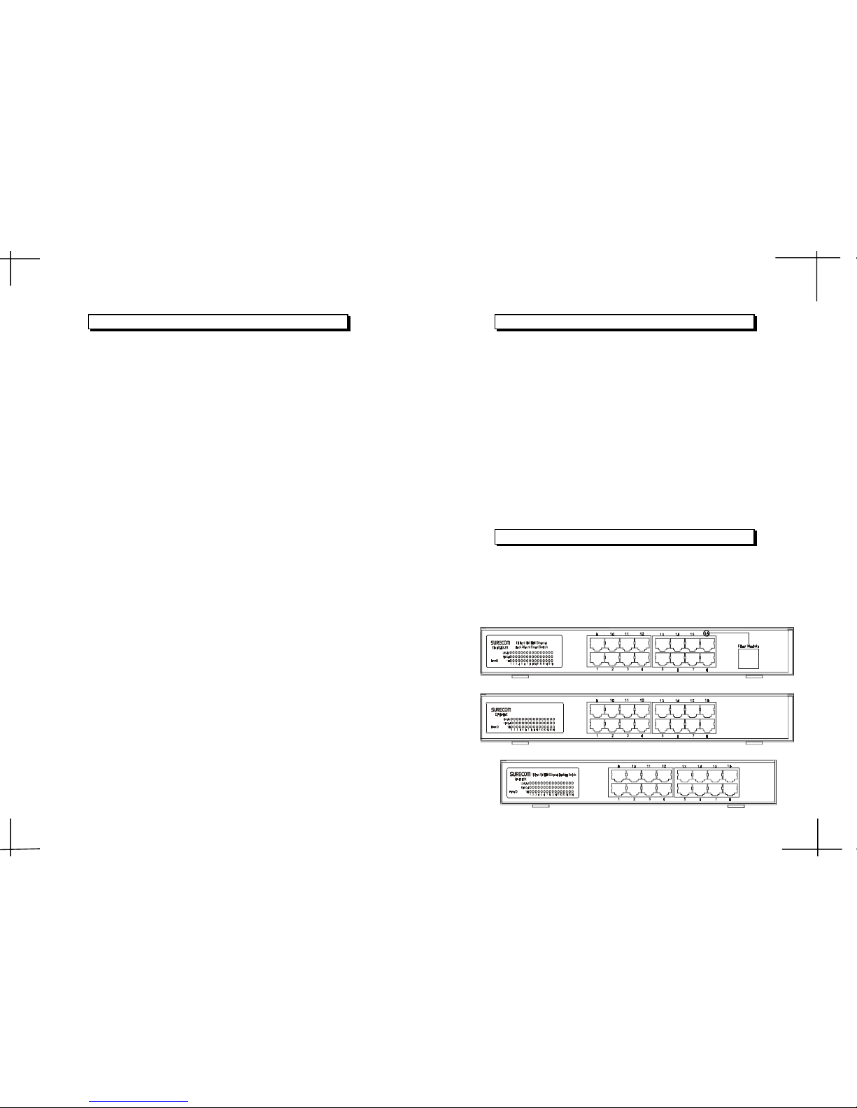
The front Panel consist of 16 10/100M RJ-45 ports,16 port LED indicators,
and one fiber port.(only 816DX-FS)
1 2
EP-816CX
EP-816DX-FS
EP-816DX
The 16-Port 10/100M Ethernet Desktop/Rack Mount Smart Switch
is the latest design in its Smart Switches series for easy installation
and high performance in an environment where traffic on the network
and the numbers of users increasing continuously. What makes the
16-Port 10/100M Ethernet Desktop/Rack Mount Smart Switch outstanding from the crowd is its built-in VLAN and Trunk configuration.
With VLAN, stations in the same LAN segment can be grouped into
different network segment. The goal of VLANs is to allow for complete
mobility of workstation placement, yet keeping broadcast traffic to a
minimum. When enabling VLAN function, the workstation only can
communicate with other workstations which are in the same VLAN
group.
With Trunk, the backbone bandwidth can be increased to advance
the network performance by easing and smoothing traffic load at
peak hours. Small businesses and corporate branch offices can take
full advantage of 100Mbps Fast Ethernet performance and preserve
existing desktop investment with no changes required to PCs, NICs,
cabling, drivers, or PC configurations.
Introduction
Page 3
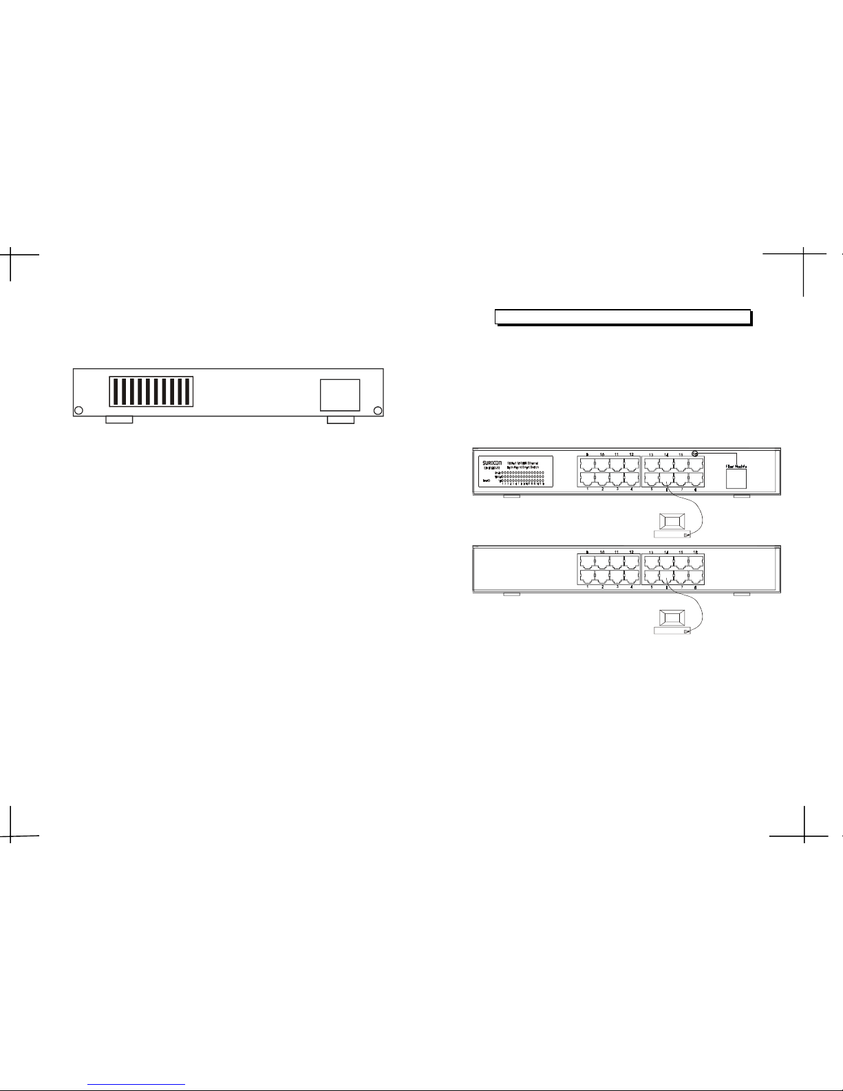
Rear Panel
LED Indicators
1. Power
This indicator operates when the Switch is turned on. If this indictor is
not lit, check the DC power connector to ensure proper insertion of the
power cord and that the power switch is turned ON.
2. Link/Act
These LED indicators are lighted up when there is a secure connection
(or link) to a device at any of the 16 ports. The LED indicators blink whenever
there is reception or transmission (i.e. Activity/ACT.) of data occurring
at any of the 16 ports.
3. FDX/Col
This LED indicator is lighted up when a respective port is in full-duplex
(FDX) mode. Otherwise, it is OFF for half-duplex (HDX) operations. It
blinks when collisions are occurring on the respective port.
The LED indicators of the Switch include Power, Link/Act (Link Activity),
FDX/COL. (Full-Duplex/Collision) and 100Mbps link speed status.
4. 100
This LED lights when the transmission rate is 100Mbps. It is OFF when
the transmission rate is 10Mbps or no linking.
Network Connections
Following describes how to connect this Switch to your Fast Ethernet
network.
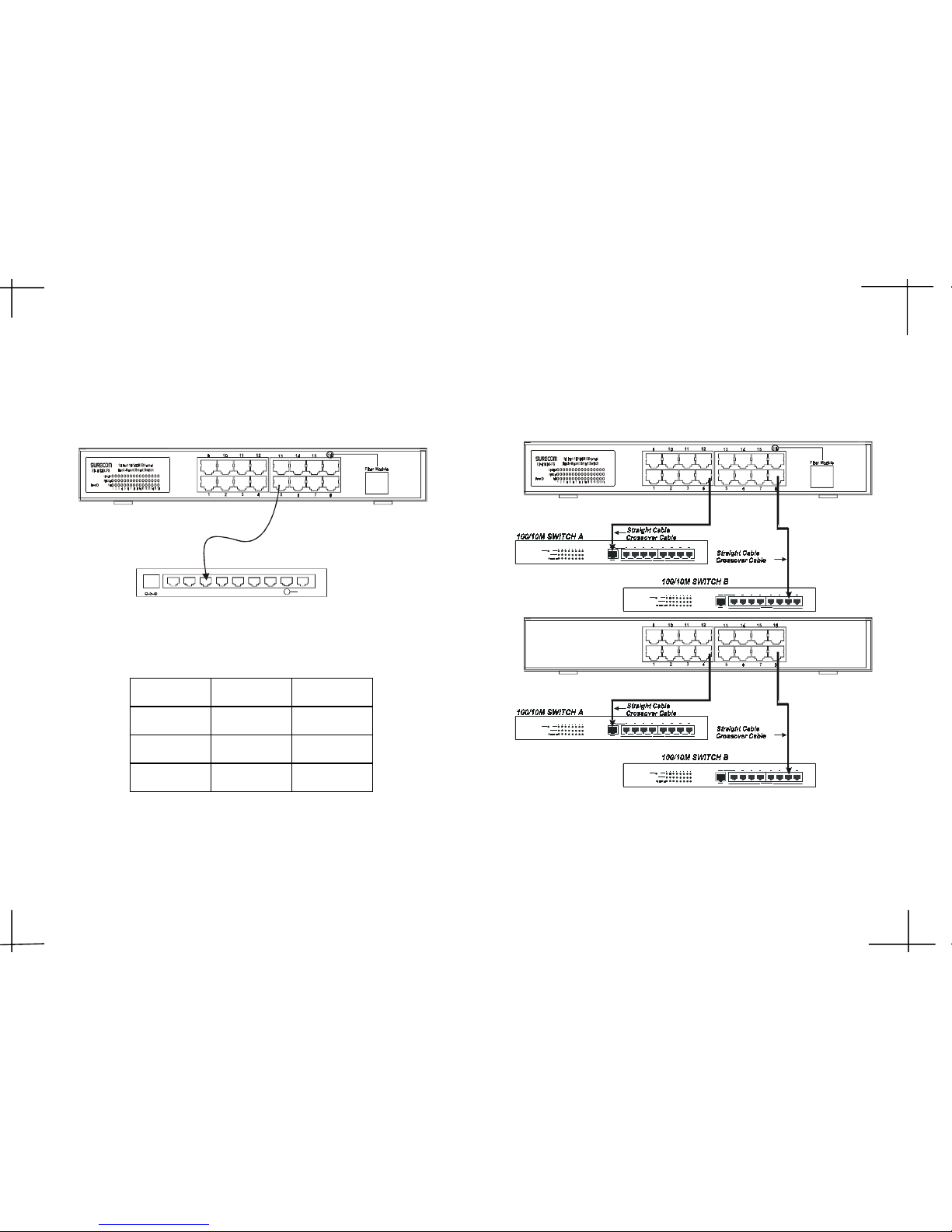
Switch to PC
A PC can be connected to the Switch via a twisted-pair Category 3, 4,5
for 10Mbps and category 5 for 100Mbps.(UTP/STP straight cable or crossover cable) The PC (equipped with a RJ-45 10/100Mbps jack) should be
connected to any of sixteen ports.
The LED indicators for PC connection are dependant on the LAN card
capabilities. If LED indicators are not illuminated after making a proper
connection, check the PC LAN card, the cable, Switch conditions and
connections.
The following are LED indicator possibilities for a PC to Switch connection:
1. The Link/ACT. LED indicator illuminates upon hookup.
2. The FDX/COL. LED indicator depends upon LAN card capabilities.
3. The 100 LED indicator comes on for a 100Mbps connection and stays
off for 10Mbps connection.
RJ-45 JACK
3 4
90~264VAC
47~63Hz
DIP 1~10
EP-816CX/DX/DX-FS
RJ-45 JACK
EP-816DX-FS
EP-816CX/DX
Page 4
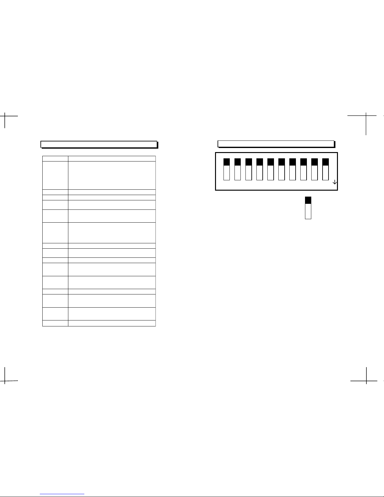
Switch to Hub
Switch to Switch (Other Devices)
DC 7.5V
8765432
Up-Link
1
5 6
EP-816DX-FS
EP-816CX/DX
the fiber cable.
When the fiber module connects to the fiber board, but it doesnt connect to
After the fiber module connects to the fiber board, you have to restart
deLroloCsutatS
kniLneerGffO
lluFneerGnO
001neerGnO
Led Status
the power again.
A 10 BASE-T Hub can be connected to the switch via a twisted-pair Category
3,4,5 UTP/STP straight cable or crossover cable. And the 100BASE-TX Hub
should be connected via Category 5 UTP/STP straight cable or crossover cable.
The Switch can be connected to another switch or other devices (routers,
bridges, etc.)via a twisted-pair Category 5 UTP/STP straight or crossover
cable for 100Mbps connection.
Page 5
Smart Function
SF-XD/XD/XC618-PE
:sdradnatStenrehtET-ESAB013.208EEEI
tenrehtEtsaFXF/XT-ESAB001u3.208EEEI
xelpuD-lluFroflortnocwolfx3.208EEEI
noitaitogen-otuataW-N3.208dtSEEEI/ISNA
tnerapsnarT:sepytemarF3.208EEEI
xelpuD-flaHroflortnocwolferusserPkcaB
:locotorPDC/AMSC
:ygolopoTratS
noissimsnarT
:dohteMdrawrof-dna-derotS
:etaRrefsnarT
:tenrehtE
:tenrehtEtsaF
)xelpuD-lluF(spbM02;)xelpuD-flaH(spbM01
)xelpuD-lluF(spbM002;)xelpuD-flaH(spbM001
:aideM
:T-ESAB01
:XT-ESAB001
:XF-ESAB001
;)m001htgnelelbac.xaM(5,4,3.taCPTU
;)m001htgnelelbac.xaM(5.taCPTU
citporebifedom-itlumnorcim521/5.26,05
citporebifedom-elgnisnorcim521/9,8
:stroPfo.oNstroP54-JRspbM01/00161
gnisuoH
:lairetaMnorI
:reffuBMARecivedrepstibM1latoT
gniretliFtekcaP
gnidrawroF/
:etaR)spbM01&spbM001rof(troprepdeeps-eriW
:rewoP)CDA5/V3.3(zH36-74,V462-09CA
:noitpmusnoCW8
:erutarepmeT
:gnitarepO
:egarotS
0
0
54~C0C
0
0
06~C0C
:ytidimuH
:gnitarepO
:egarotS
%09~%01
%59~%5
:ecnamrofnoCAssalCkraMEC,AssalCCCF
Technical Specifications
1 2 3
4
5 6 7 9 10
1: Enable the VLAN function on each port.
0: Disable the VLAN function on each 16 ports. (default)
DIP 1:
Ext. Port#1,12 as one group, Port#2,12 as one group....
DIP 2:
1: Enable port trunk 0 which consists of ports 5,6,13,14
DIP 3:
DIP 4:
7 8
Enable Port Based VLAN configuration function:
VLAN topology type selection:
1:Select 15 VALNs (port#1~11,13~16) with 1 overlapping port
(port#12) topology.
Enable Port Trunk 0:
Enable Port Trunk 1:
OFF:0
ON:1
0
1
DIP 8
ON
.0: Disable port trunk 0
1: Enable port trunk 1 which consists of ports 7,8,15,16
Ext. Port#1,4,12 as one group, Port#2,4,12 as one group....
0: Disable port trunk 1
0:Select 14 VLANs(port#1~3,5~11,13~16)with 2 overlapping ports
(port#4,12)topology.(default)
Page 6
DIP 6:
DIP 7/8:
00: Disable port based priority. (default)
01: Set port 5,13 as high priority ports.
10: Set port 5,6,13,14 as high priority ports.
11: Set port 5~8,13~16 as high priority ports.
DIP 9:
1: Enabled
0: Disabled (default)
DIP 10:
1: Enabled
High Priority: if pattern bits TOS/DS[0:5] =(EF) 101110;(AF)
001010, 010010,011010, 100010;(Network Control)
11x000;Low Priority: if TOS/DS = other codepoint values.
0: Disabled (default)(DS = Differentiated Service)
9
Note:1. If any physical port of a trunk group has a link down,
a fault condition has happened on this trunk group.
Enable Port Trunk 2:
Enable Port Trunk 3:
Enable Port based priority QoS function:
Enable 802.1p VLAN Tag priority based QoS function:
Enable TCP/IP TOS/DS (DiffServ) based QoS function:
2. After you change the status of any DIP, you have to restart
the switch again.
DIP 5:
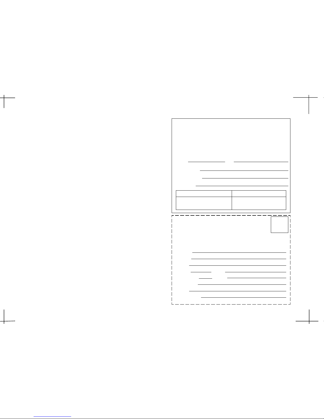
2-Year Warranty2-Year Warranty
2-Year Warranty2-Year Warranty
2-Year Warranty
The manufacturer warrants to the original consumer /purchaser free from defects
in materials or workmanship for limited time from the original factory shipment
date.
KEEP THIS STUB FOR YOUR RECORDS
Date Purchased:
Where Purchased:
From Whom:
Serial:
Model:
TO:
ATTN:
Place
Stamp
Here
WARRANTY REGISTRATION CARDWARRANTY REGISTRATION CARD
WARRANTY REGISTRATION CARDWARRANTY REGISTRATION CARD
WARRANTY REGISTRATION CARD
Please complete this form and return it within 10
days of purchase to validate the warranty
Name/Title:
Company:
Address:
Tel. No.: Signature:
Purchase Model: Serial No.:
Purchase from:
Address:
Date of Purchase:
MANUFACTURER DISTRIBUTOR
1: Enable port trunk 2 which consists of ports 1,2,9,10
1: Enable port trunk 3 which consists of ports 3,4,11,12
0: Disable port trunk 2
0: Disable port trunk 3
 Loading...