

Page 1

8-Port 100/10M
N-Way Mini Switch
7IAH\I/KE@A
:sdradnatS:sdradnatS
:sdradnatS
:sdradnatS:sdradnatStenrehtET-ESAB013.208EEEI
tenrehtEtsaFXT-ESAB001u3.208EEEI
noitaitogen-otuayaW-N3.208dtSEEEI/ISNA
tnerapsnarT:sepytemarF3.208EEEI
setyB8151-46:ezisemarfreyalCAM3.208EEEI
xelpuD-lluFroflortnocwolfx3.208EEEI
:locotorP:locotorP
:locotorP
:locotorP:locotorPDC/AMSC
:ygolopoT:ygolopoT
:ygolopoT
:ygolopoT:ygolopoTratS
noissimsnarTnoissimsnarT
noissimsnarT
noissimsnarTnoissimsnarT
:dohteM:dohteM
:dohteM
:dohteM:dohteMdrawrof-dna-erotS
:etaRrefsnarT:etaRrefsnarT
:etaRrefsnarT
:etaRrefsnarT:etaRrefsnarT
)xelpuD-lluF(spbM02;)xelpuD-flaH(spbM01:tenrehtE
)xelpuD-lluF(spbM002;)xelpuD-flaH(spbM001:tenrehtEtsaF
:aideM:aideM
:aideM
:aideM:aideM
;)m001(5,4,3.taCPTUriaP-2:T-ESAB01
)m001(PTSmho-001865-AIT/AIE
;)m001(5.taCPTUriaP-2:XT-ESAB001
)m001(PTSmho-001865-AIT/AIE
:stroPfo.oN:stroPfo.oN
:stroPfo.oN
:stroPfo.oN:stroPfo.oNstrop54-JRspbM01/001thgiE
/gniretliFtekcaP/gniretliFtekcaP
/gniretliFtekcaP
/gniretliFtekcaP/gniretliFtekcaP
:etaRgnidrawroF:etaRgnidrawroF
:etaRgnidrawroF
:etaRgnidrawroF:etaRgnidrawroF)spbM01&spbM001rof(troprepdeeps-eriW
:noisnemiD:noisnemiD
:noisnemiD
:noisnemiD:noisnemiD)HxWxL(mm5.23x5.001x8.381
:noitpmusnoC:noitpmusnoC
:noitpmusnoC
:noitpmusnoC:noitpmusnoC)xaM(sttaw5
:erutarepmeT:erutarepmeT
:erutarepmeT
:erutarepmeT:erutarepmeT
0:gnitarepO
0
55~C0C
0:egarotS
0
56~C0C
:ytidimuH:ytidimuH
:ytidimuH
:ytidimuH:ytidimuH
%09~%01:gnitarepO
%59~%5:egarotS
:ecnamrofnoC:ecnamrofnoC
:ecnamrofnoC
:ecnamrofnoC:ecnamrofnoCAssalCkraMEC,AssalCCCF
%
Technical Specifications
#471808XR00Z0
www.surecom-net.com
www.surecom.com.tw
EP-808X-R
Page 2
This users guide is applied to the 8 ports 100/10M
N-Way Mini Switch . The 8-Port 100/10M N-Way
Mini Switch is designed for easy installation and
high performance in an environment where traffic
on the network and the number of users increase
continuously. Small businesses and corporate
branch offices can now take full advantage of
100Mbps Fast Ethernet performance and preserve
existing desktop investment with no changes
required to PCs, NICs, cabling, drivers, or PC
configurations.
_
One 8-Port 100/10M N-Way Mini Switch
_
One External Power Adapter
_
Two Screws
_
Two Anchors
_
This Users Guide
Introduction
Package Contents
Hardware
The following describes the front panel, rear panel
and LED indicators of the 8-Port 100/10M N-Way
Mini Switch .
_
Provide one Uplink port for uplink to another
switch, hub or repeater
_
Store-and-forward switching scheme capability to
support rate adaptation and ensures data integrity
_
Auto-negotiation on each port.
_
Auto-polarity detection for correction of incorrect
polarity on the received twisted pair on each port
_
Data forwarding rate 148,800 pps per port at 100%
of wirespeed
_
Data filtering rate eliminates all error packets, runts,
etc. at 148,800 pps per port at 100% of wire-speed
_
The shortest forwarding latency time
_
Conforms to IEEE 802.3 10BASE-T and IEEE 802.
3u 100BASE-TX standards
_
Eight 100/10Mbps RJ-45 ports
_
Support store-and-forward mode switching
_
Full and Half-Duplex mode operation
_
IEEE802.3x flow control for Full-Duplex operation
_
Back pressure for Half-Duplex flow control
_
Support one Uplink port for expansion
_
Auto-negotiation capability
_
Source address learning and aging function
_
LEDs to indicate : TEST, Speed/ACT.,FDX/COL.,
and Power status
Key Features
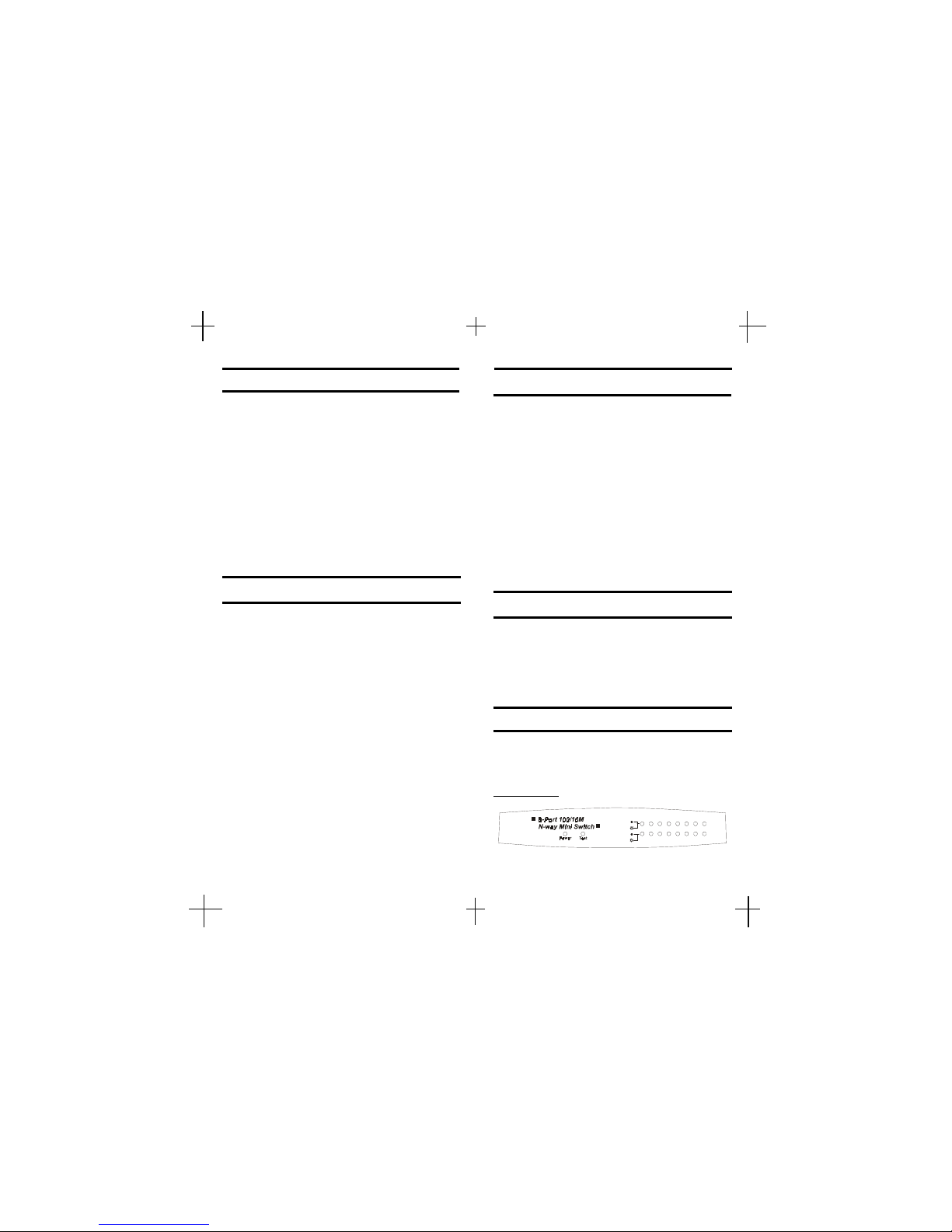
Front Panel
!"#$ &%
Speed
Act.
FDX
Col.
Performance Highlights
Page 3

DELroloCsutatSnoitpircseD
forebmuN
DEL
rewoPneerGnOnorewoP1
tseTwolleYnO
rorretsetpooL
srucco
1
.tcA/deepS
neerG
nO
fospbM001
tropdetcennoc
)8-1(8
gnihsalF
atadrofspbM001
gniviecer
wolleY
nO
fospbM01
tropdetcennoc
gnihsalF
atadrofspbM01
gniviecer
.loC/XDFneerG
nO
fosutatsxelpuD-lluF
tropdetcennoc
)8-1(8
gnihsalF
fosrucconoisilloC
M001roM01
1. Uplink
The Uplink port is used to connect to other
switches or hubs. The Uplink port is shared with
the port #1.
2. RJ-45 Ports
Eight N-Way Mini RJ-45 STP ports all come with
auto-negotiation and operate at 100/10Mbps for
connection to servers and hubs. All ports can be
configurated for Full/Half-Duplex mode.
3. Power Connector
For the external 7.5V DC power adapter that
connects to power outlet.
Rear Panel
LED Indicators
The following figures illustrate the connections of
8-Port N-Way Mini Switch.
PC to Switch
A PC can be connected to the 8-Port N-Way Mini
Switch via a two-pair Category 3/4/5 UTP/STP
straight cable. The PC (equipped with a RJ-45 100/
10Mbps jack) should be connected to any of eight
ports.
The 8-Port N-Way Mini Swit ch
Note: The LED indicators for PC connection are dependant on the LAN card
capabilities. If LED indicators are not
illuminated after making a proper
connection, check the PC LAN card, the
cable, the N-Way Mini Switch conditions
and the connections.
!"
Network Connection
Page 4
FCC Statement
This equipment can generate, use and radiate radio
frequency energy and, if not installed and used in accordance with the instructions in this guide, may cause
interference to radio communications. This equipment has
been tested and found to comply with the limits for a Class
A computing device pursuant to Subpart J of Part 15 of the
FCC rules, which are designed to provide reasonable
protection against radio interference when operated in a
commercial environment. Operation of this equipment in
a residential area is likely to cause interference, in which
case the user, at his own expense, will be required to take
whatever measures are necessary to correct the
interference.
CE Declaration of conformity
This equipment complies with the requirements relating to
electromagnetic compatibility, EN 55022 class A for ITE
and EN 50082-1. This meets the essential protection
requirements of the European Council Directive 89/336/
EEC on the approximation of the laws of the Member
States relating to electromagnetic compatibility.
Trademarks
All company, brand, and product names are trademarks or
registered trademarks of their respective companies.
1-Year Warranty
The manufacturer warrants to the original consumer /
purchaser free from defects in materials or workmanship for limited time from the original factory shipment
date.
DISTRIBUTOR
Date Purchased:
Where Purchased:
From Whom:
Model: Serial :
!
!
TO:
ATTN:
WARRANTY REGISTRATION CARD
Please complete this form and return it within 10
days of purchase to validate the warranty
Name/Title:
Company:
Address:
Tel. No.: Signature:
Purchase Model: Serial No.:
Purchase from:
Address:
Date of Purchase:
Place
Stamp
Here
KEEP THIS STUB FOR YOUR RECORDS
MANUFACTURER
SURECOM
Copyright 2000 by SURECOM Technology Corp.
All rights reserved.
c
Copyright
No part of this guide may be reproduced by any means
without written permission from SURECOM Technology
Corp., except that the purchaser may copy necessary
portions for internal use only.
Page 5

The following are LED indicator possibilities for a
PC to the N-Way Mini Switch connection:
1. The Speed/Act. LED indicator illuminates upon
hookup.
2. The FDX/Col. LED indicator depends upon
LAN card capabilities.
Switch to Hub
A hub (10BASE-T or 100BASE-TX) can be connected to the N-Way Switch via a two-pair Category 3/4/5 UTP/STP straight cable. The connection is accomplished from any normal port of the NWay Mini Switch to the uplink port of the connected hub.
Hub without Uplink Port
Using straight cable
When using straight cable, the connection can be
made from the Uplink port shared with the port #8
of the 8-Port N-Way Mini Switch to any port of the
Hub (see figure 3-3.
Using crossover cable
When using crossover cable, the connection can
be made from any port (the port #1-8) of the 8-Port
N-Way Mini Switch to any port of the Hub (see
figure 3-3).
The 8-Port N-Way Mini Switch
HUB
The 8-Port N-Way Mini Switch
Crossover Cable
Straight Cable
HUB A
HUB B
#$
 Loading...