

Page 1

EP 802X
2-Port N-Way Switch
User Manual
T471802X00ZZ1
Size: 14.5 cm x 20.5 cm (WxL)
Material: Cotton paper( ) 100pounds
Page 2

Table of Contents
Chapter 1 Introduction
General Description
Feature Highlights
Key Features
Package Contents
Chapter 2 Hardware Description
Front Panel
Rear Panel
Chapter 3 Hardware Installation
Making Network Connection
Switch Operation
Appendix A Technical Specifications
Appendix B Troubleshooting
Appendix C System Diagnosis
Appendix D Order Information
1
1
1
3
4
7
7
8
11
12
15
17
18
19
20
i ii
FCC Statement
This equipment generates, uses and can radiate radio frequency energy and,
if not installed and used in accordance with the instructions in this manual,
may cause interference to radio communications. This equipment has been
tested and found to comply with the limits for a Class A computing device
pursuant to Part 15 of the FCC rules, which are designed to provide reasonable protection against radio interference when operated in a commercial
environment. Operation of this equipment in a residential area is likely to
cause interference, in which case the user, at his own expense, will be
required to take whatever measures are necessary to correct the interference.
CE Declaration of Conformity
This equipment complies with the requirements relating to electromagnetic
compatibility, EN 55022 class A for ITE and EN 50082-1. This meets the
essential protection requirements of the European Council Directive 89/336/
EEC on the approximation of the laws of the Member States relating to
electromagnetic compatibility.
Trademarks
SURECOM® , EP-802X , Mini-Stack ™ , Fanless-Cooling™ , SOHO-Net™
are registered trademarks of SURECOM T echnology Corp.
All other brands and product names may be registered trademarks or trademarks of their respective holders.
Copyright 1998 SURECOM Technology Corp. All rights reserved. No part of this
documentation may be reproduced, translation, adaptation in any form without
the permission from the publisher.
Page 3

1 - Introduction
General Description
EP-802X provides a series of 2-Port Fast Ethernet 100/10Mbps N-Way
Switches introduced specifically for backbone network expansion where
high-bandwidth applications are being used and bottlenecks may be inhibiting network performance. EP-802X supports auto-sensing 100/10Mbps
and Full/Half-Duplex on each port for 100BASE-TX and 10BASE-T
integration without replacing your any existing network equipment and
cabling. EP-802X is designed for plug-and-play installation. No software
or hardware configuration is necessary. It is a simple affordable way to
boost performance and expand the network architecture.
Feature Highlights
• Fiber Optic Support
EP-802X comes with two ST or SC Multimode Fiber module for
choice. They are EP-802-FT and EP-802X-FC individually. The
Fiber optic support enables you to expand the network size and
connect with fiber environment. With this particular characteristic,
fiber optic connector can process data transmission better and lower
the data loss reliably.
This page was intentionally left blank
1
Page 4

• Elegant and Compact Design
With state-of-the-art design, EP-802X looks elegant streamlined
sleek and slim-sized, and is outstanding among the competitors. EP802X is one part of Surecoms SOHO-Net family. The sleek
blue-green EP-802X products can be easily stacked together with
our Z-fixers. Of course, they can be stacked with Surecoms any
SOHO-Net products, such like dual-speed Hub, high density port
N-Way Switch, and Internet access device. The stack will be more
easier and convenient for space saving, network maintenance and
management.
• Advanced User-friendly Features
The EP-802X features utilization LED indicators on the front
panel which displays the network utilization status of bandwidth
used. Besides, the EP-802X is able to connect without Autosensing device and force itself in pure 100Mbps or 10Mbps speed
in order to match your environment flexibly. It is a very useful and
user-friendly function for non-technical and technical people.
Key Features
q Conforms with IEEE 802.3 10BASE-T and IEEE 802.3u 100BASE-
TX/FX standards
q Supports two RJ-45 Shielded-Twisted-Pair ports and two Uplink port
in each device
q Supports Auto-negotiation for 100/10Mbps and Full/Half-Duplex
operation
q Switching and learning at 148,800 packets/sec rate in Full-Duplex
mode
q Using store-and-forward technology for the best loading-balance and
total throughput
q Back-pressure flow control for Half-Duplex operation
q Supports connection with 100/10Mbps Ethernet Adapter or Hub
without Auto-negotiation or Parallel Detection capability
q 5 utilization and 1 Buffer-full LEDs to indicate the network traffic
q Optional Fiber optic slide-in module to upgrade EP-802X with fiber
capability
q Supports RAM self-test when prowered on and show the result in
LEDs
2 3
Page 5
Package Contents
Your EP-802X package includes the following items:
√ One 2-Port Fast Ethernet N-Way Switch Hub
√ One AC Power Adapter
√ Four rubber Feet
√ Two tapping screws
√ Two nylon screws andiron
√ Two plastic Z-fixers
√ One user Manual
If any pieces are missed or damaged, please contact your supplier immediately.
4 5
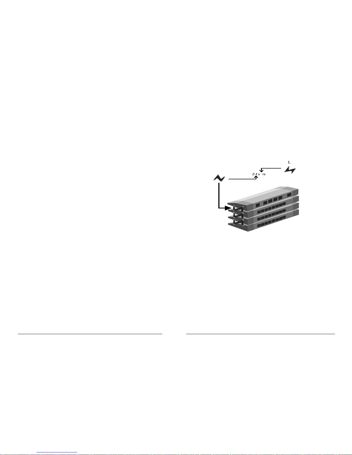
Note: Z-fixers are used to scale Surecoms SOHO-Net
family
for convenient management. This is not used to stack hubs
as traditional. Z-fixers are composed by right and left fixer
each. Illustraion is followed as below:
Page 6
6 7
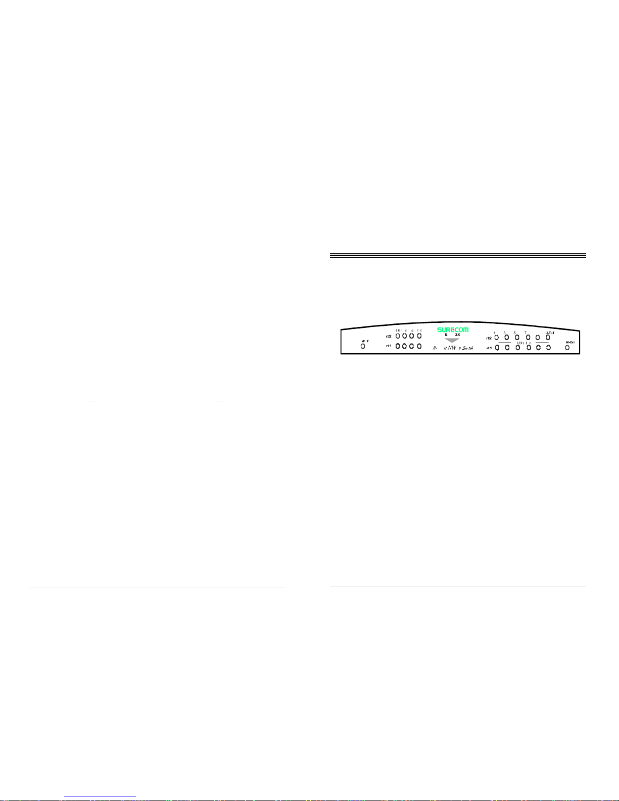
Front Panel
2 - Hardware Description
Each LED indicator represents a different function and will help you
monitor the status of each port and connected segments.
This page was intentionally left blank
Power : The LED is ON when the hub is powered up.
10M : The LED shows the linking status is in 10Mbps speed.
100M : The LED shows the linking status is in 100Mbps
speed.
Act : This signal indicates the port activity. The LED shows
that data is transmitted or received.
FDX : Full/Half Duplex. This signal indicates the port in
Full or Half-duplex mode. (LED ON: Full-Duplex;
LED OFF: Half-Duplex)
10%~90% : These LEDs display the utilization percentage in 10%,
30%, 50%, 70%, or 90%.
Buffer-Full :
The LED is ON when the received buffer is full.
RAM-Err : Memory self-test. The whole test takes about 6 ms.
The RAM-Err LED will be turn red if any data read is
different from written.
Page 7
8 9
Rear Panel
LED Indicators
Function
LED Color Total
#
On Flash Off
Power
10M
100M
Act
FDX
Green
Green
Green
Green
Green
1
2
2
2
2
Power On
10Mbps
100Mbps
Port Active
Full-Duplex
-
-
-
-
-
Power off
-
-
-
Half-Duplex
Utilization
10%
30%
50%
70%
90%
Green
Green
Green
Yellow
Yellow
2
2
2
2
2
Traffic loading to 10%
Traffic loading to 30%
Traffic loading to 50%
Traffic loading to 70%
Traffic loading to 90%
-
-
-
-
-
-
-
-
-
Buf-Full
RAM-Err
Red
Red
21Buffer Full
RAM Error
-
-
-
-
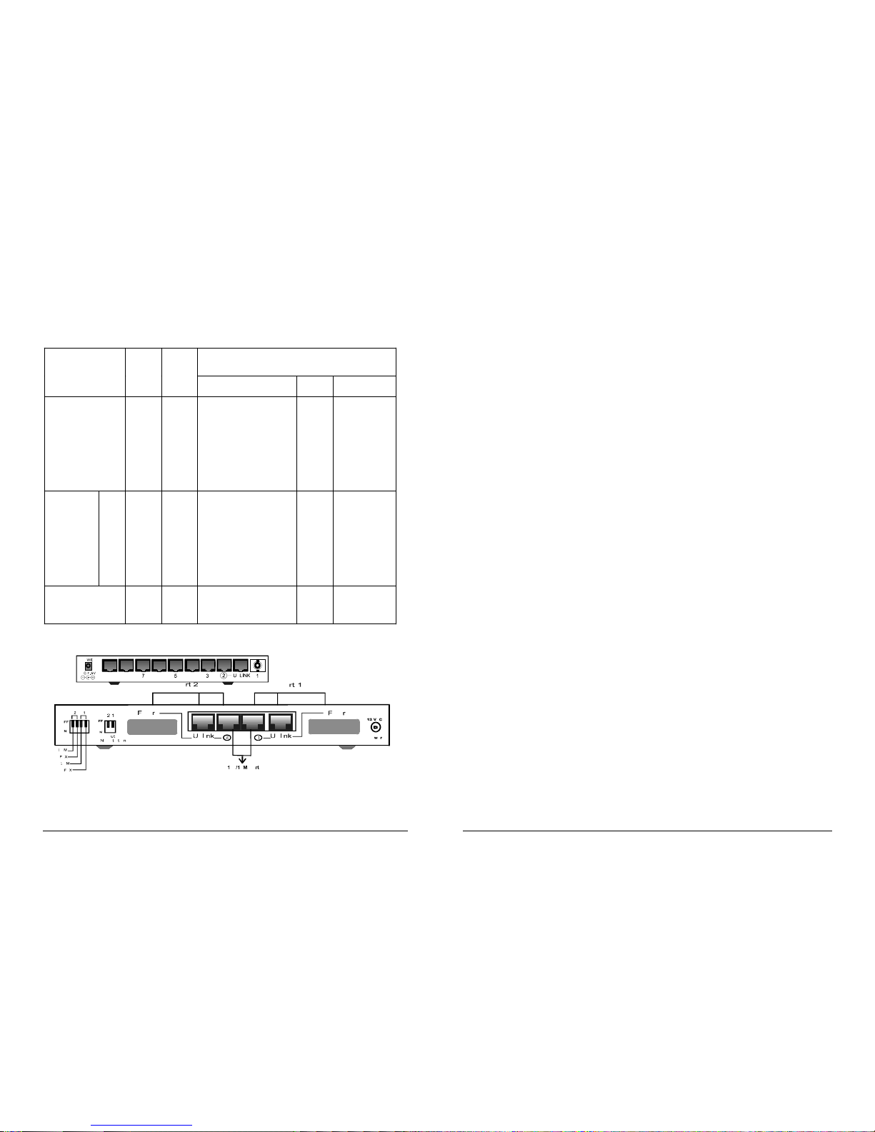
Power Socket : Plug the AC power adapter into this port.
Fiber Optic Connector : This 2-Port N-Way Switch can be applied to
any DTE (Data Terminal Equipment)/
Repeater equipped with Fiber module.
Uplink Port : The Uplink port is used to connect a
Hub/Repeater for extending nodes on the
network.
100/10M Port : This RJ-45 100/10M port is to connect a DTE
such as a workstation/server.
Note: You can only use one of above three connectors (Fiber optic
connector, Uplink port, or 100/10M port) at a time.
Auto-Negotiation
Switch
: This switch is for enable/ disable Auto-
Negotiation (N-Way) function. (On- enable
Auto-Negotiation; Off- disable AutoNegotiation)
100M Switch : Enable/disable 100Mbps. (Dip 100M On-
enable 100M and operate in 100M speed. Dip
100M Off- disable 100M and operate in 10M
speed)
FDX Switch : Full/Half-Duplex function. (Dip FDX on-
Full-Duplex; Dip FDX off- Half-Duplex)
Page 8

Note:Port 1/Port2: Including three connectors: Fiber optic con-
nector, Uplink port, and 100/10M port. Please make sure
100M switch turn ON before you slide fiber module into this
port. As a result, Auto-Negotiation Switch will be disabled.
You can only use one of this: Fiber optic connector, Uplink
port, or 100/10M port when connecting. (Fiber module is
provided optional.)
10 11
3 - Hardware Installation
This chapter gives you brief description of the EP-802X and provides
installation procedures for use with your system.
1. Unpack the switch.
2. Find a location close to the network devices you need to connect,
and within easy reach of an electrical outlet.
3. Mount the switch on a desktop or any other flat surface. If you are
installing multiple switches, you can stack them on top of each other
(after attaching the foot pads).
4. Connect PCs or other network devices to the switchs ports.
- Connect any device that use a standard network interface to
the 100/10M port for 100/10M connections (e.g., a worksta tion, server, bridge or router).
- To cascade to another switch or hub, connect straight-through a
twister-pair cable to the Uplink port on this switch to
any RJ-45 port on the other device. You need to use UTP cable for
RJ-45 connections: Category 5 cable for 100Mbps connections. Be
sure that the length of any twisted-pair connection does not exceed
100 meters (328 feet).
Port1 Port2
Port
Switch
Dip On Dip Off Dip On Dip Off
Auto-
Negotiation
Switch
Enable A/N Disable A/N Enable A/N Disable A/N
100Mbps 10Mbps 100Mbps 10Mbps
100M/FDX
Switch
Full Half Full Half
Page 9
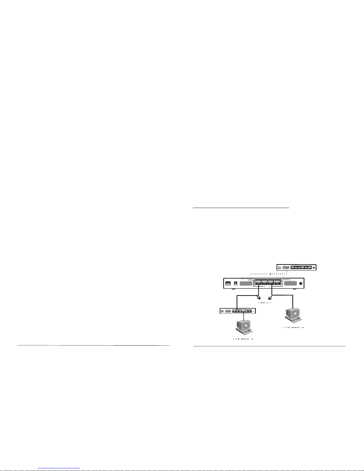
5. The 2-Port Fast Ethernet N-Way Switch can be used as a collapsed
backbone for small networks, or can be attached to an network interconnection device via one of the 100/10 Mbps Fast Ethernet port.
6. Verify network communications by ensuring that
- You have made all the necessary connections
- You can access any connected resources
- The switchs indicator LEDs are functioning properly
Making Network Connection
The 2-Port Fast Ethernet Switch provides a segmented network architecture. Any port can be attached to a shared collision domain or provide a
dedicated link to a single network device. When a port on the switch is
connected to an Ethernet/Fast Ethernet hub, the bandwidth provided by
that port is shared by all the devices connected to the attached hub.
However, when a port is connected to an end mode, or to a device that
breaks up the collision domain (e.g., another switch, bridge or router), the
attached device has access to the full bandwidth provided by that port.
• Bridging Function
The switch provides fully transparent bridging functions which
automatically learn node addresses, which are subsequently used to
filter and forward all traffic based on the destination address. When
traffic passes between devices attached to the same shared collision
domain, those devices attached to the same shared collision domain,
and those packets are filtered from the switch. But when traffic
must be passed between unique segments (i.e., different ports on
the switch), a temporary link is set up between the switch ports
which need to pass this traffic, via the high-speed switching fabric.
• Flexible Configuration
This switch is not only designed to segment your network, but also
to provide a wide range of options in setting up network connections. It can be used as a simple stand-alone switch; or can be
connected with standard hubs, switched, or other network interconnection devices in various configurations.
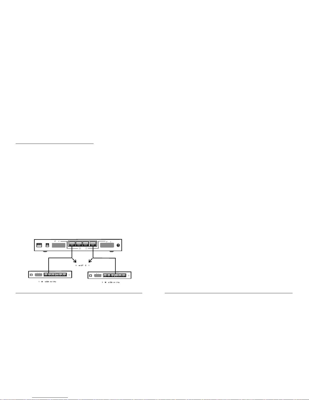
1. Connection for a 10 and 100 Mbps Device
The 100/10M port in each port section (port1/2) is used in conjunction with RJ-45 moduler plug via UTP. Be sure to use the proper
cable wiring to connect your switching hub. Category 5 cable is
recommended in this case. Soon-to-be connected workstations could
be key PCs, servers, or other network devices directly to the switching hub in either 100 or 10 Mbps speed.
12 13
Page 10
Note: You can connect fiber optic connector to another device
with fiber port. However, you can only choose one
conneting option with fiber optic connector, Uplink port, or
100/10M port at a time.
2. Connection for 100 Mbps Hubs Extend
For most Fast Ethernet hub, the uplink UTP cable must not over 5m to
keep the data transmission reliability. On the other hand, the 2-port
switching hub is integrated with a smart 100 Mbps extender function,
enabling you to use the 100m Category 5 UTP cable wiring to link a Fast
Ethernet Hub on any given port. This improvement allows you to connect as many hubs as you need.
♦EP-802X could be configured as a 2-port bridge between a
10Base-T and 100Base-TX environment or severed in a fast
Etherent 100Mbps environment.
♦The maximum between EP-802X and the connected device is 100
meters.
Switch Operation
• Address Table
The Ethernet Switching is implemented with a filtering address
table. This address table composed of many entries. Each entry is
used to store the address information of some node in the network,
including MAC address, port ID, etc. This information comes from
the learning process of Ethernet Switching.
• Learning
When one packet comes in from any port, the Ethernet Switching
will record the source address, port ID, and the other related information in address table. This information will be used to decide
either forwarding or filtering for future packets.
• Forwarding & Filtering
When one packet comes from some ports of the Ethernet Switch,
it will also check the destination address besides the source address
learning. The Ethernet Switch will look up the address table for
the destination address. If not found, this packet will be forwarded
to all the other ports except the port which this packet comes in.
And these ports will transmit this packet to the network it connected. If found, and the destination address is located at different
port from this packet comes in, the Ethernet Switching will forward this packet to the port where this destination address is
located according to the information from address table. But if the
destination address is located at the same port with this packet
11
11
1
44
44
4 15
Page 11

• Store-and-Forward
Store-and-Forward is one type of packet-forwarding techniques. A
Store-and-Forward Ethernet Switch stores the incoming frame in an
internal buffer and check error before transmission. Therefore, no
error packets occur when buffers are received from end users. It is
the best choice when a network needs efficiency and stability.
The Ethernet Switch scans the destination address from the packet
header, searches the routing table provided for the incoming port
and forwards the packet, only if required. The fast forwarding
makes the switch attractive for connecting servers directly to the
network, thereby increasing throughput and availability. However,
the switch is most commonly used to segment existing hubs, which
nearly always improves overall performance. An Ethernet Switch
can be easily configured in any Ethernet network environment to
significantly boost bandwidth using conventional cabling and adapters.
Due to the learning function of the Ethernet Switching, the source
address and corresponding port number of each incoming and
outgoing packet are stored in a routing table. This information is
subsequently used to filter packets whose destination address is on
the same segment as the source address. This confines network
traffic to its respective domain, reducing the overall load on the
network.
16 17
Appendix A: Technical Specifications
comes in, then this packet will be filtered. Thereby increasing the
network throughput and availability.
Standard : IEEE 802.3 10BASE-T
IEEE 802.3u 100BASE-TX/FX
Access Method : Store & Forward
Connectors : 4 RJ-45 standard ports (including 2 Uplink ports and 2
100/10M ports); 2 optional ST/SC type fiber optic
ports for EP-802X-FT/FC modules
Media Support : Cat.5 UTP cable (100BASE-TX)
Cat.3 UTP cable (10BASE-T)
Multi-mode fiber cable (100BASE-FX)
Max. Length
Cable
Optical Fiber::
100m (Switch to Hub/Node)
412m
2000m (Switch to Switch in Full-Duple mode)
Power
Consumption
Adapter
::Max. 15 watts
Input 100-240V (50-60 Hz); Output AC 12V/1.5A
Net Weight : 450g
Dimensions :
22.5cm¡Ñ12.2cm¡Ñ3.5cm (L¡ÑW¡ÑH)
Temperature : 5ºC~55ºC (operating); 0ºC~65ºC (storage)
Humidity : 10%~90% (operating); 5%~90% (storage)
Conformance
EMI
EMS
::FCC Class A, CE
CE
Page 12

18 19
Appendix B: Troubleshooting Appendix C: System Diagnostics
Installation
Verify that all system components have been properly installed. If one
or more components appear to be malfunction (e.g., the power adapter
or network cabling), test them in an alternate environment where you
are sure that all the other components are functioning properly.
Cabling
1. Verify that the cabling type is correct. Be sure all cable connectors
are securely seated in the required ports. Use straight-through cable
for all standard connections.
2. Make sure all devices are connected to the network. Equipment may
have been unintentionally disconnected from the network.
Symptom Solution
Power indicator does not light
up (green) after power on.
Step 1. Check the power outlet by
plugging into another device
and see if it is functioning
properly.
Step 2. Check the power adapter with
another device.
If these measures fail to resolve the
problem, have the units power supply
replaced by a qualified distributor.
The 10M or 100M LED
shows off after cable is
connected to the 100/10M
port.
Step 1. Make sure you connect to DTE
(Data terminal equipment) to
the 100/10M port for
100/10M connections.
Step 2. Verify that the other end of
the UTP cable is connected to
the device that is powered on
and on-line.
Step 3. Check the UTP is connected to
100/10M port not the
Uplink ports.
Page 13

20
Appendix D: Order Information
Three main model available:
1. EP-802X: 2-Port Fast Ethernet N-Way Switch with 2 RJ-45
Connectors
2. EP-802X-FT: 2-Port Fast Ethernet N-Way Fiber Switch
with ST-type Fiber Optic Connectors
3. EP-802X-FC: 2-Port Fast Ethernet N-Way Fiber Switch
with SC-type Fiber Optic Connectors
 Loading...