

Page 1

EP-726DG
24+2G Rock-Mount
Management Switch
Users Manual
www.surecom-net.com
#471726DGZ000
Page 2

FCC Statement
This equipment can generate, use and radiate radio frequency energy and, if not
installed and used in accordance with the instructions in this manual, may cause
interference to radio communications. This equipment has been tested and found to
comply with the limits for a Class A computing device pursuant to Part 15 of the FCC
rules, which are designed to provide reasonable protection against radio interference
when operated in a commercial environment. Operation of this equipment in a residential area is likely to cause interference, in which case the user, at his own expense, will
be required to take whatever measures are necessary to correct the interference.
CE Declaration of Conformity
This is a Class A product. In a domestic environment product may cause radio
interference in which case the user may be required to take adequate measures.
Trademarks
All other brands and product names may be registered trademarks or trademarks of their
respective holders.
Page 3

Content
Chapter 1
1.Introduction-----------------------------------------------------------------------------------1
2.Features----------------------------------------------------------------------------------------1
3.Package Contents---------------------------------------------------------------------------2
Chapter 2
1.Hardware--------------------------------------------------------------------------------------3
2.LED Indicators-------------------------------------------------------------------------------4
Chapter 3
1.Technical Specification---------------------------------------------------------------------6
Chapter 4 Software
1.Web Management Overview--------------------------------------------------------------7
2.Port Status-------------------------------------------------------------------------------------9
3.Port Statistics--------------------------------------------------------------------------------11
4.Administrator--------------------------------------------------------------------------------12
4.1 IP Address--------------------------------------------------------------------------------------12
4.2 Switch Settings--------------------------------------------------------------------------------13
4.3 Console Port Information------------------------------------------------------------------16
4.4 Port Controls----------------------------------------------------------------------------------17
4.5 Trunking----------------------------------------------------------------------------------------19
4.6 Filter Database-------------------------------------------------------------------------------22
4.7 VLAN configuration-------------------------------------------------------------------------25
4.8 Spanning Tree---------------------------------------------------------------------------------30
4.9 Port Sniffer------------------------------------------------------------------------------------32
4.10 SNMP-----------------------------------------------------------------------------------------33
4.11 Security Manager---------------------------------------------------------------------------35
4.12 802.1X Configuration---------------------------------------------------------------------36
4.13 TFTP Update Firmware------------------------------------------------------------------39
4.14 Configuration Backup---------------------------------------------------------------------40
4.15 Reset System---------------------------------------------------------------------------------41
4.16 Reboot----------------------------------------------------------------------------------------42
Page 4

Chapter 5
Configuration of Management Function--------------------------------------------43
Chapter 6 Console-Menu Line---------------------------------------------------------44
6.1 Main Menu--------------------------------------------------------------------------------------45
6.2 Switch Static Configuration-----------------------------------------------------------------46
6.2.1 Port Configuration--------------------------------------------------------------------47
6.2.2 Trunk Configuration------------------------------------------------------------------49
6.2.3 VLAN Configuration-----------------------------------------------------------------50
6.2.4 Misc Configuration-------------------------------------------------------------------56
6.2.5 Administration Configuration----------------------------------------------------- 60
6.2.6 Port Mirroring Configuration------------------------------------------------------63
6.2.7 Priority Configuration---------------------------------------------------------------64
6.2.8 Mac Address Configuration--------------------------------------------------------65
Chapter 7 Protocol Related Configuration
7.1 STP---------------------------------------------------------------------------------------------67
7.2 SNMP------------------------------------------------------------------------------------------70
7.3 GVRP------------------------------------------------------------------------------------------75
7.4 IGMP------------------------------------------------------------------------------------------76
7.5 LACP----------------------------------------------------------------------------------------- 77
7.6 802.1X----------------------------------------------------------------------------------------81
Chapter 8 Status and Counters-------------------------------------------------------84
8.1 Port Status----------------------------------------------------------------------------------85
8.2 Port Counters------------------------------------------------------------------------------86
8.3 System Information-----------------------------------------------------------------------87
Chapter 9 Reboot Switch---------------------------------------------------------------88
9.1 Default--------------------------------------------------------------------------------------88
9.2 Restart--------------------------------------------------------------------------------------88
Chapter 10 TFTP Update Firmware------------------------------------------------89
10.1 TFTP Update File----------------------------------------------------------------------89
10.2 Update Configure File----------------------------------------------------------------91
10.3 Upload Configure File----------------------------------------------------------------92
Page 5

Congratulations on your purchase of SURECOMs 24+2G Rack-Mount Management
Switch. It delivers the Gigabit speedy data transmission to meet your increasing
bandwidth requirement. Powerful and practical smart functions supported make this
switch be the perfect tool for your network planning or bandwidth allocating.
This high-performance, cost-effective switch is the best solution to increasing
bandwidth requirement.
EP-726DG with 24 100/10Mbps ports plus 2 Gigabit port modules, gives the highest
efficiency for extending or upgrading your network infrastructure. Via its high bandwidth,
it provides high performance connectivity between workgroups and servers. It also can
easily enhance your backbone performance, just slide Gigabit module in. Moreover, with
Trunk function supported, it provides the more convenient usage of bandwidth.
1. Introduction
EP-726DG provides smart function to manage the networking environment, such as
VLAN, Trunk. It supports port-based VLAN. With the VLAN groups, users can be easily
classified in logical without physical limitation. EP-726DG also supports Broadcasting
Filtering function to prevent network congestion.
Key Features
Supports SNMP, Web-based, Telnet and Console Management
MIB:MIB II, Ethernet/Bridge MIB
RMON:4 Groups (1,2,3,9)
Supports Port-based VLAN and IEEE802.1Q Tag-based VLAN (up to 256 groups)
Supports Trunking: Up to 7 trunking groups
Supports Port Mirroring
Supports the Spanning Tree Protocol: IEEE802.1D
Page 6

Check the contents of your package for following parts:
One 24+2G Gigabit Ethernet Smart Switch
One Users manual
One Power cord
One RS-232 Cable
One set of Rack-Mount Bracket
If any of the items are missing or damaged, please contact your local dealer.
Package Contents
Page 7
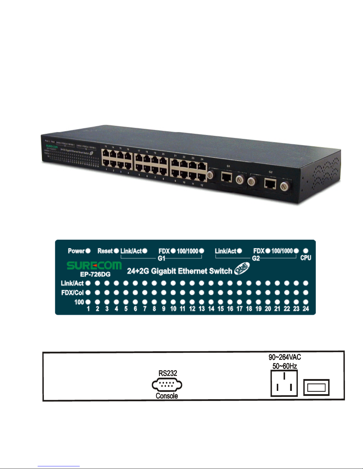
2. Hardware
This section describes the hardware features of this Gigabit Ethernet Smart Switch.
For easier management and control of the switch, familiarize yourself with its display indicators and ports. All LEDs are located on the front panel of the switch. They serve the
purpose of monitoring the operation and performance of the switch at a glance.
Front Panel
EP-726DG-S
Rear Panel
!
Page 8

LED Indicators
Power: System power indication. When power on system, it will light green.
The Other LEDs dedicated to each port for showing ports status.
DELroloCsutatSnoitircseDDELforebmuN
UPCneerG
nOydaeRedoMUPC
gnihsalFybdnatS
.tcA/kniLneerG
nOnOkniLdnastroP001/01*42
troPtibagiG*2
gnihsalFytivitcA
ffOffOkniL
001neerG
nOedoMspbM001
stroP001/01*42
ffOedoMspbM01
0001/001
neerGnOedoMspbM0001
stroPtibagiG*2
deRnOedoMspbM001
loC/XDFneerG
nO
fosutatsxelpuD-lluF
tropdetcennoc
dnastroP001/01*42
stroPtibagiG*2
gnihsalF
troppust'nod(noisilloC
)eludoMagiG
gnihsalFedoMxelpuDflaH
Note: When the Fiber Module works, the Link/Act LED is always linghting, not flashing.
Optional Modules
EP-101G-TX 1 Port 100/1000M Gigabit Copper Module
EP-101G-SC 1 Port 1000BASE-SX Gigabit SC Type Fiber Module
* Please contact with your dealers to order or get more information.
Reset
Reset: Hardware Reboot. After reset, system will reboot automatically.
"
Page 9

No. of Network Ports
1.10/100Mbps RJ-45 ports: Twenty Four
2.Expansion Slot: Two for one 1000BASE-T or 1000BASE-SX Gigabit port module.
Console Port
The console port interface conforms to the RS-232 electrical specification and locates
on the front panel. This interface supports asynchronous data of eight data bits, one stop
bit, and no parity bit. The unit only operates at 9600bps rates with RS-232 cable in
system configure.
Network Connection
All ports of this switch support Auto-MDI/MDI-X. So you can connect any device
(including PC, Switch, Hub) to a port of this switch via a regular cable. The RJ-45 port will
auto-detect and auto-switch to the correct MDI/MDI-X mode. (Do not need to connect to
a specific uplink port or cross-over cable)
Connect one end of the network cable to the RJ-45 port on the front panel, and connect
the other end of the network cable to the RJ-45 port on the network device. Follow the
same procedure to connect all the RJ-45 ports of the switch. Maximum length, using UTP
cable, between the switch and connected device is 100 meters (300ft). Once the network
cable is connected to both ends and the attached network device is powered on, the
LINK/ACT LED should be lit.
Note: Make sure the wiring is correct. You need to use Category 3/4/5 cable for 10Mbps
operation or Category 5 cable for 100/1000Mbps connections.
#
Page 10

EP-726DG
:sdradnatStenrehtET-ESAB013.208EEEI
tenrehtEtsaFXT-ESAB001u3.208EEEI
xelpud-llufroflortnocwolFx3.208EEEI
T-ESAB0001ba3.208EEEI
XS-ESAB0001z3.208EEEI
noitagerggaknilda3.208EEEI
:aideM
:T-ESAB01
:T-ESAB001
:T-ESAB0001
:XS-ESAB0001
XL-ESAB0001
5,4,3.taCPTU
puro5.taCPTU
puro5.taCPTU
mu521/5.26,521/05edom-itluM
mu521/9,521/8edom-elgniS
M001/01fo.oN
:troPstrop54-JR*42
:noitpOeludoMtroP noitpoeludomtroptibagiGrebiFroreppoCrofstolsni-edils2
:troPelosnoC9-BD232-SR*1
:teseRnottuBteseR*1
sserddACAM
:elbaTK41
:reffuBMARsetyBK215
:lortnoCwolF xelpud-flahroferusserpkcaB,xelpud-llufroflortnocwolF
edom
:NALV pu(NALVdesab-gaTQ1.208EEEIdnaNALVdesab-trop
)spuorg652ot
:knurTspuorggniknurt7otpU
:BIMBIMegdirB/tenrehtE,IIBIM
:NOMR)9,3,2,1(spuorG4
:DELUPC,0001,001,LOC/XDF,tcA/kniL,rewoP
:ylppuSrewoP)zH06-05,V042-001CA(rewoPhctiwSlanretnI
:erutarepmeT
:gnitarepO
:egarotS
0
0
54~C
0
C
02-
0
07~C
0
C
:ytidimuH
:gnitarepO
:egarotS
%09~%01
%09~%01
:ecnamrofnoCAssalCkraMEC,AssalCCCF
$
3. Technical Specification
Page 11

2-Year Warranty
The manufacturer warrants to the original consumer /purchaser free from defects
in materials or workmanship for limited time from the original factory shipment
date.
KEEP THIS STUB FOR YOUR RECORDS
Date Purchased:
Where Purchased:
From Whom:
Model: Serial:
MANUFACTURER
DISTRIBUTOR
WARRANTY REGISTRATION CARD
Please complete this form and return it within 10
days of purchase to validate the warranty
Name/Title:
Company:
Address:
Tel. No.: Signature:
Purchase Model: Serial No.:
Purchase from:
Address:
Date of Purchase:
Place
Stamp
Here
Page 12
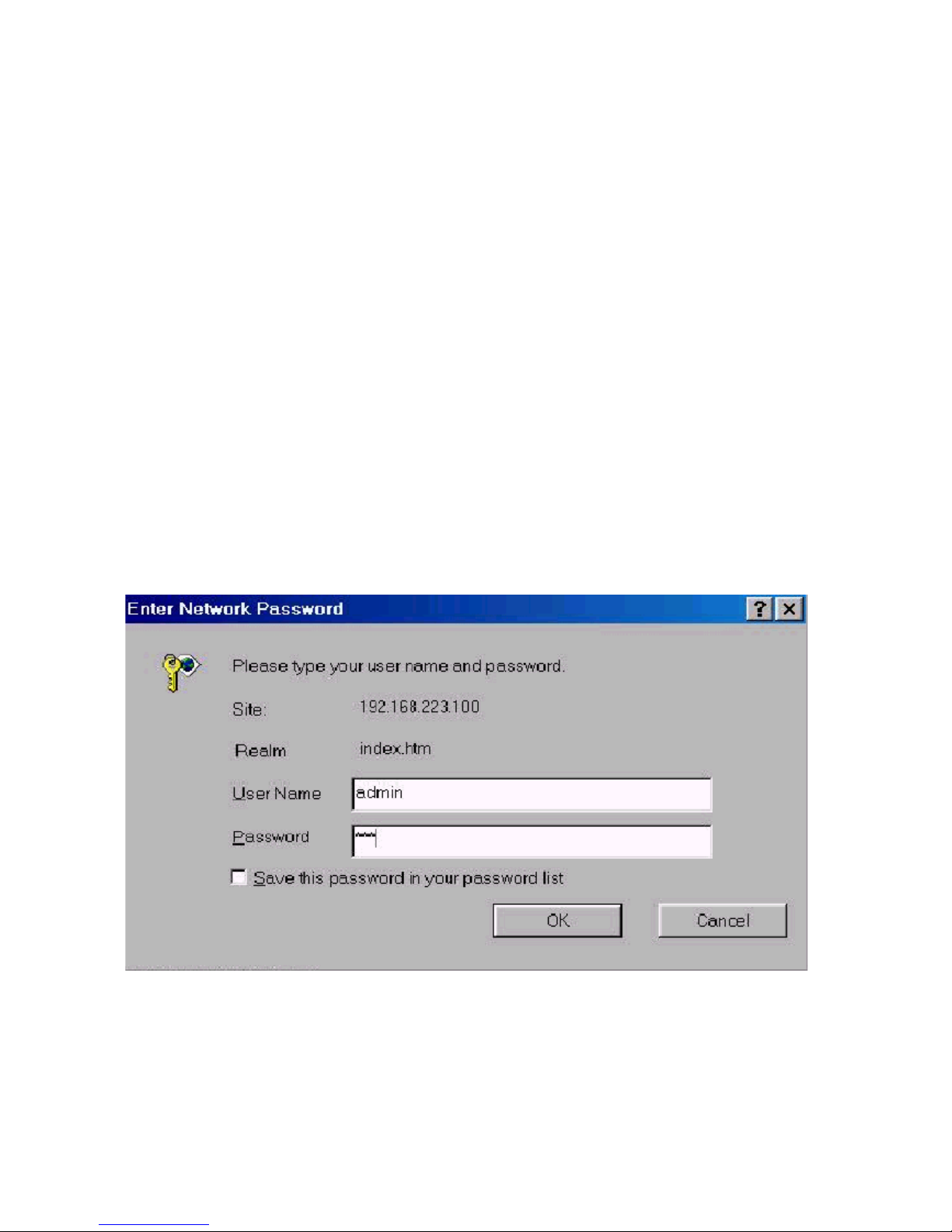
1. Web Management Overview
This switch provides a web browser to manage and monitor.
The default values are as follows:
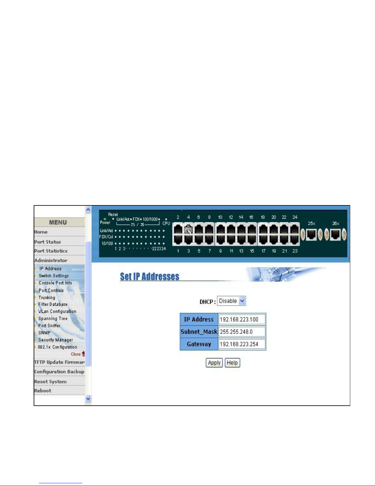
IP Address: 192.168.223.100
Subnet Mask: 255.255.248.0
Default Gateway: 192.168.223.254
User Name: admin
Password: 123
You can browse http://192.168.223.100, type user name
and password as below.
%
4. Software
Page 13
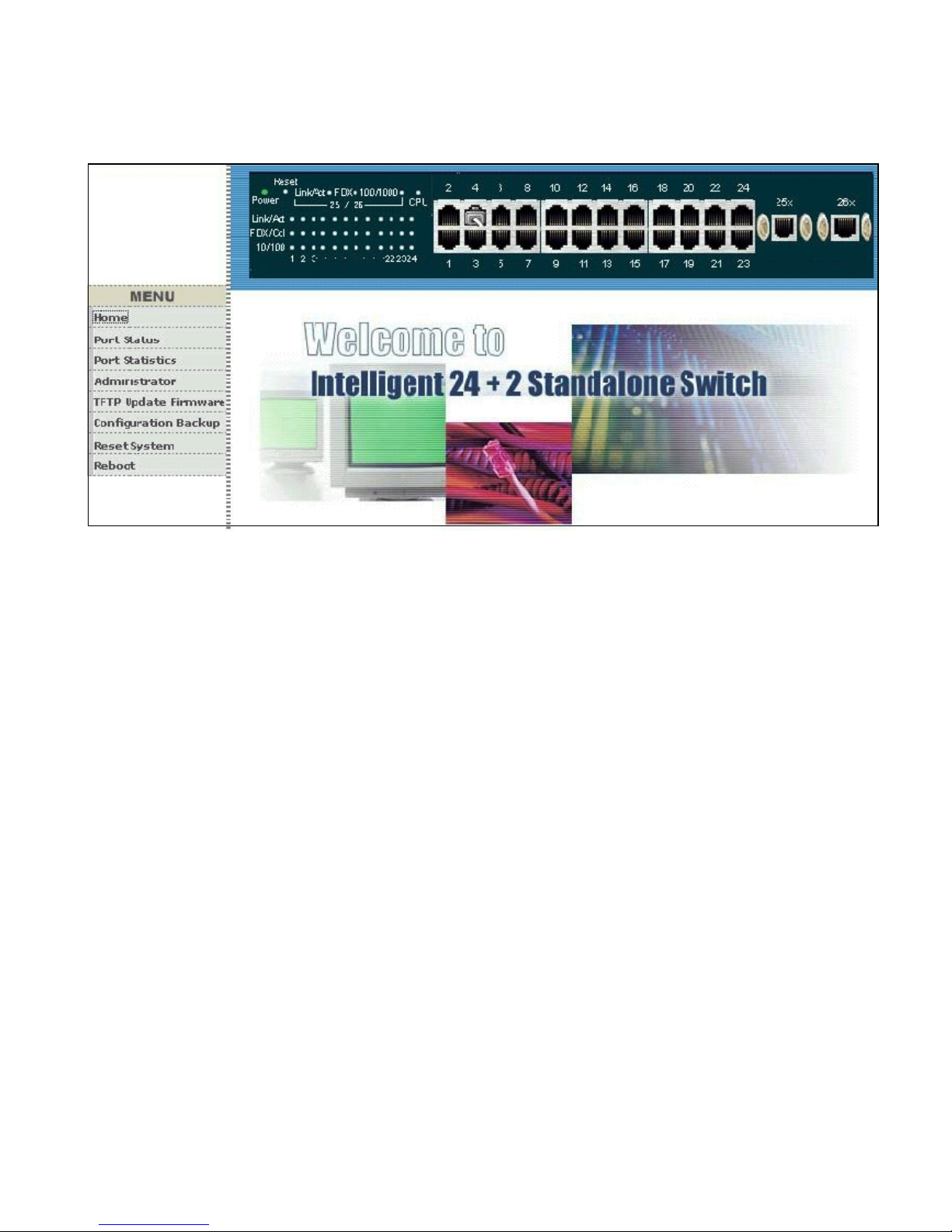
After type in the correct username and password, you can see the homepage as follows:
&
Page 14

2.Port Status
Click the port status icon on the menu column you will see the port status page. In this page, you can
see the status of each port that depended on users settings and the negotiation results.
'
Page 15
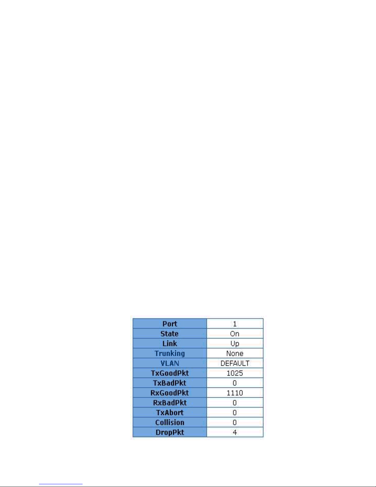
1. State: Displays the status of each port (on means enable and off means disable). Unlink will be
treated as off .
2. Link Status: Down and Up means No Link and Link respectively.
3. Negotiation: Displays the auto negotiation modes: auto, force and nway-force.
4. Speed status: Displays the speed of each port: Port 1- 24 are 10/100Mbps(Fast Ethernet Switch)
Port 25-26 are 10/100/1000Mbps (Gigabit Ethernet Switch)
5. Duplex status: Displays the port is full-duplex mode or half-duplex mode.
6. Flow Control:
Full: Displays the flow control status is enable or disable in full duplex mode.
Half: Displays the backpressure is enable or disable in half duplex mode.
7. Rate Control: Displays the rate control settings.
Ingr: Displays the ports effective ingress rate of user settings. Egr: Displays the ports effective egress
rate of user settings.
8. Port Security: Shows the port security is enabled or disabled.
9. Config: Displays the state of users settings.
10. Atual: Displays the negotiation results.
You can see a single port counter by clicking on each port as following.
Page 16
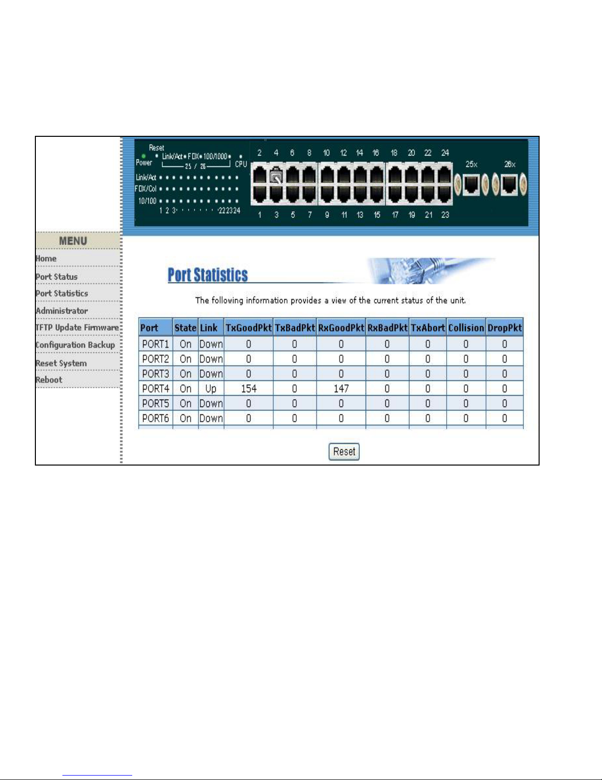
3.Port Statistics
The following information provides a view of the current status of the switch. Press Reset button to
clean all count.
Page 17
4. Administrator
This management switch provides advance features, which offers you more flexibility in setting up your
network. The following sections explain how to set up the IP address,Switch settings, Console port
information, Port controls,Trunk configuration, Filter database, VLAN configuration,Spanning tree, Port
Sniffer, SNMP management, Security Manager, TFTP Update Firmware, Configuration Backup,
Reset system and Reboot etc.
4.1 IP Address
You can configure the IP Settings and fill in the new values, than click Apply button. You must restart
the switch then use new IP address to browse this web management.
Page 18
4.2 Switch Settings
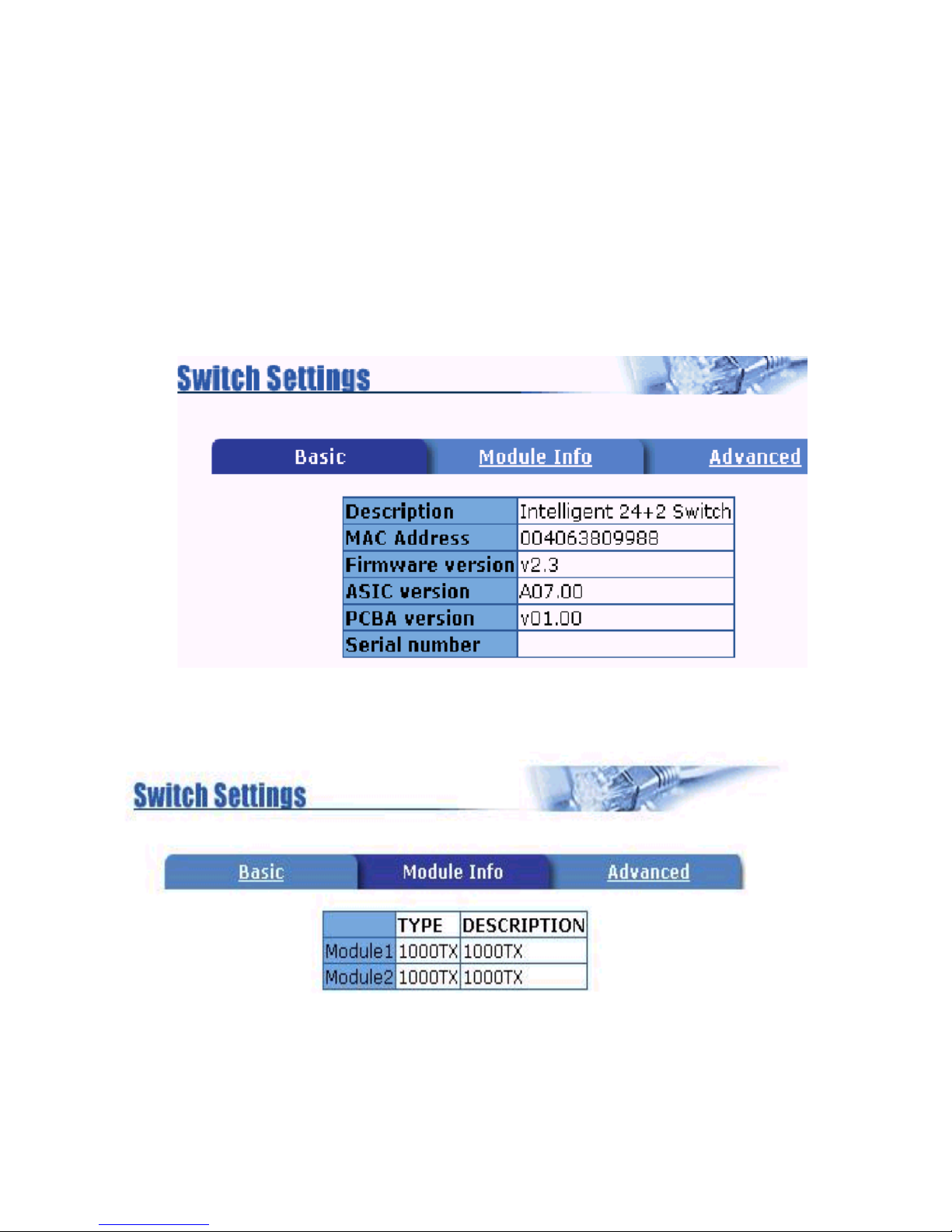
4.2.1 Basic
Description: Displays the name of this management switch.
MAC Address: The unique hardware address is assigned by manufacturer (default).
Firmware Version: Displays the switchs firmware version.
ASIC Version: Displays the switchs Hardware version.
PCBA version: Displays the switchs PCBA version.
Serial number: The serial number is assigned by manufacturer.
4.2.2 Module Info
Displays the module card informations.
Note:
The module type will be 1000TX for Copper module 1000FX-Full only for Fiber module.
!
Page 19
4.2.3 Advanced
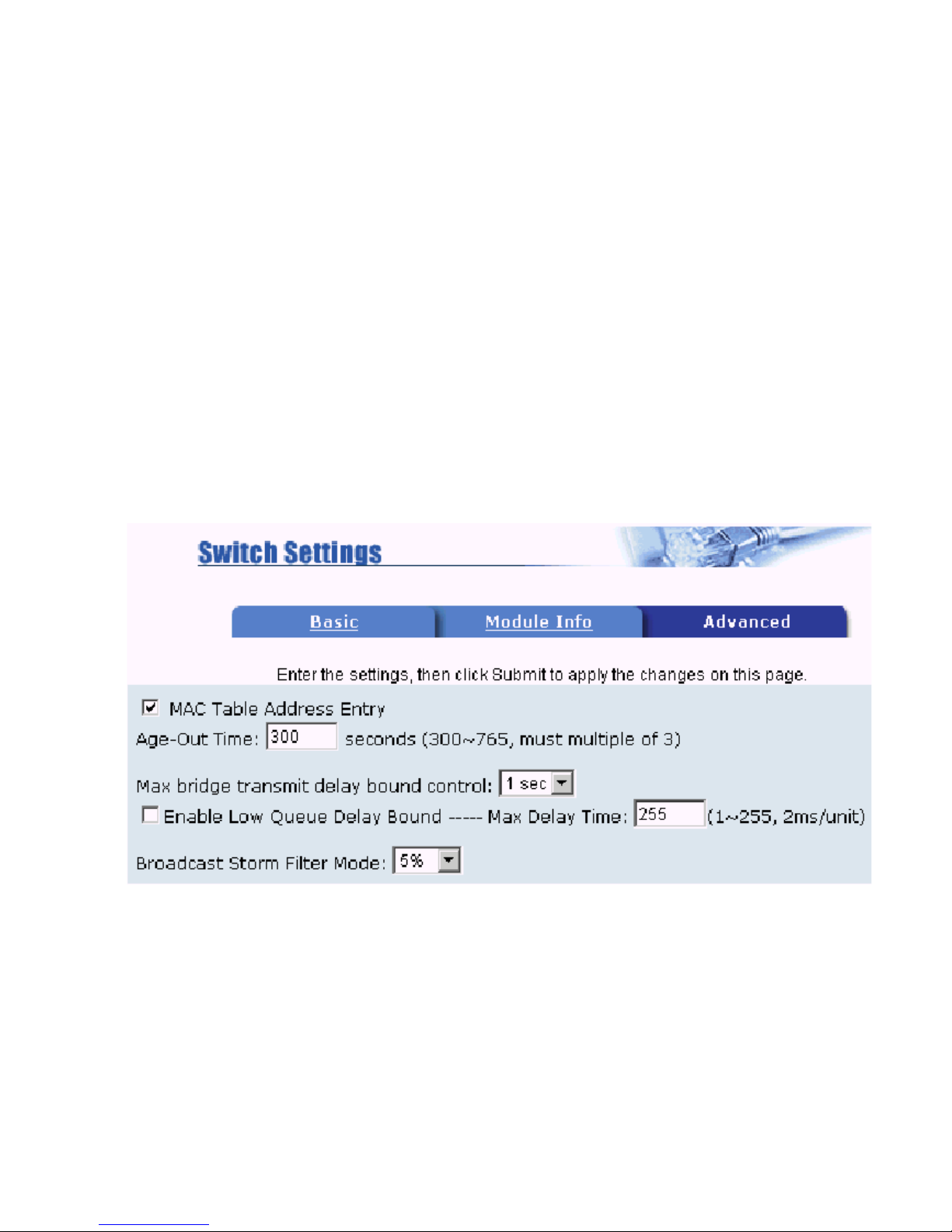
Miscellaneous Settings:
MAC Address Age-out Time: Type the number of seconds that an inactive MAC address remains in
the switchs address table.
The valid range is 300~765 seconds. Default is 300 seconds.
Max bridge transit delay bound control: Limit the packets queuing time in switch. If enable, the
packets queued exceed the time will be droped. This valid value are 1sec, 2 sec, 4 sec and off. Default
is 1 second.
Broadcast Storm Filter Mode: To configure broadcast storm control, enable it and set the upper
threshold for individual ports.
The threshold is the percentage of the ports total bandwidth used by broadcast traffic. When broadcast
traffic for a port rises above the threshold you set, broadcast storm control becomes active. The valid
threshold value are 5%, 10%, 15%, 20%, 25% and off.
Priority Queue Service settings:
First Come First Service: The sequence of packets sent is depend on arrive order.
All High before Low: The high priority packets sent before low priority packets.
WRR: Weighted Round Robin. Select the preference given to packets in the switchs high-priority
queue. These options represent the number of high priority packets sent before one low priority packet
is sent. For example, 2 High : 1 Low means
"
Page 20
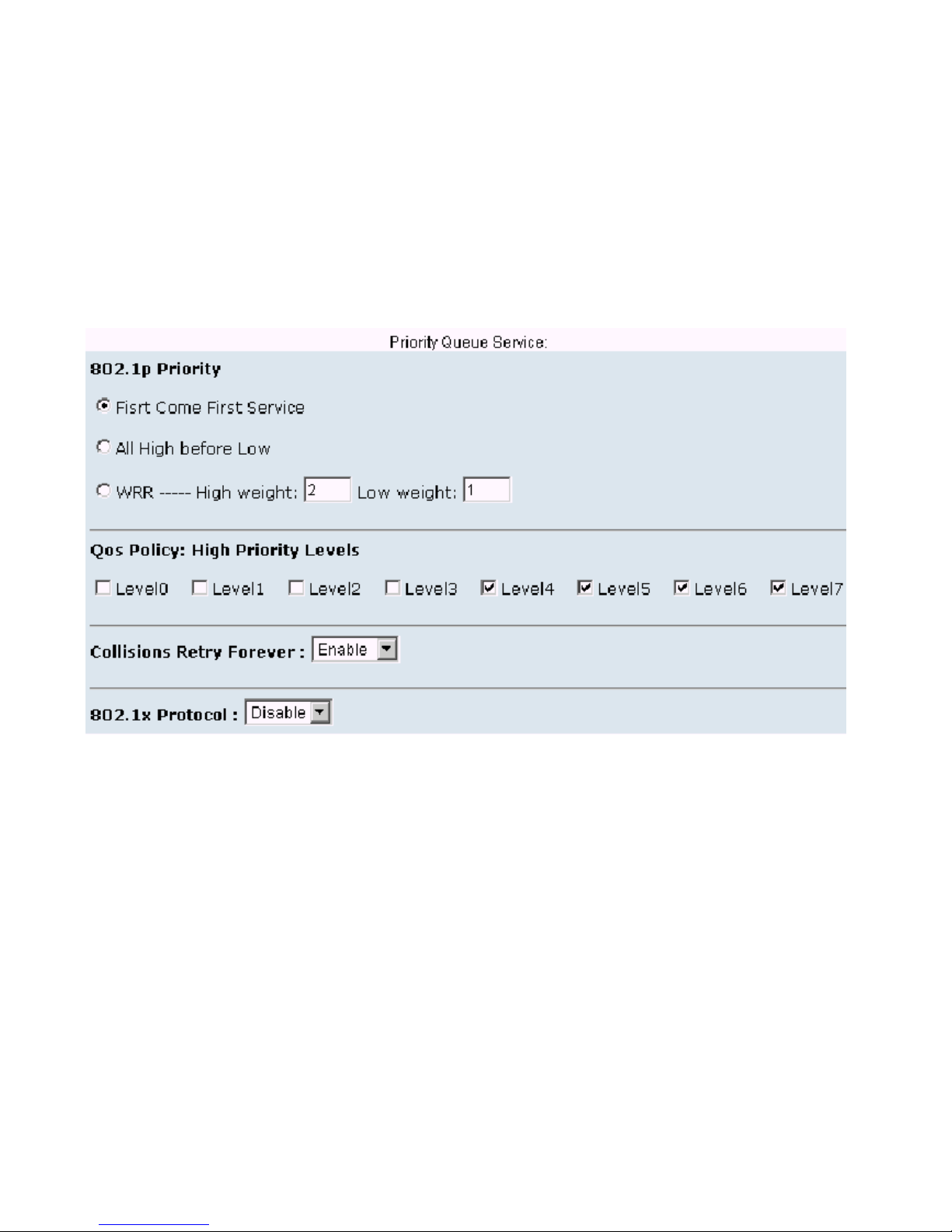
that the switch sends 2 high priority packets before sending 1 low priority packet.
Qos Policy: High Priority Levels, 0~7 priority levels, can map to high or low queue.
Collisions Retry Forever: Enable it or just disable this function.
802.1X Protocol: IEEE 802.1X is port-based authentication protocol. You can enable it to control
users access to the internet.
#
Page 21
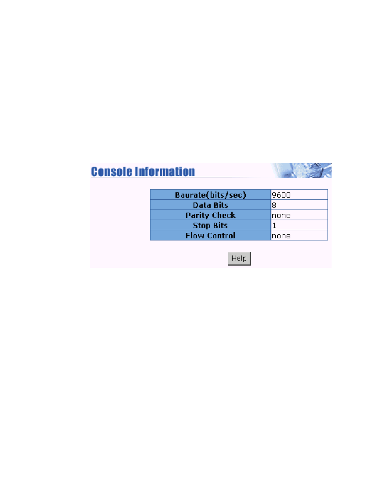
4.3 Console Port Information
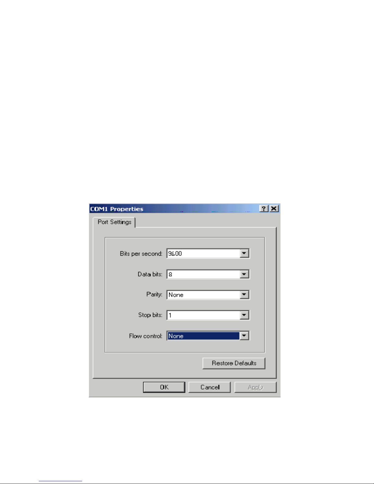
Console is a standard UART interface to communicate with Serial Port. You can use windows
HyperTerminal program to link the switch. Connect To->Configure
Bits per second: 9600
Data bits: 8
Parity: none
Stop Bits: 1
Flow control: none
$
Page 22
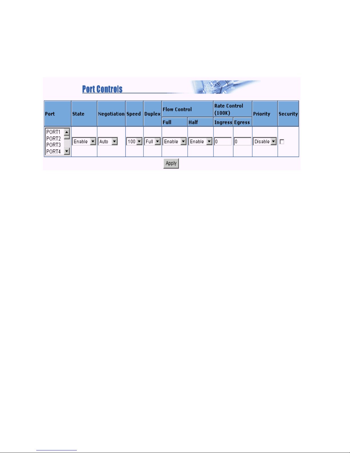
4.4 Port Controls
You can change the status of each port in this page.
1.State: You can enable or disable this port.
2.Auto Negotiation: You can set auto negotiation mode as Auto,Nway (specify the speed/duplex on
this port and enable auto-negotiation) or Force of each port.
3.Speed: You can set 100 or 10Mbps speed on Port1~Port24. And set 1000/100/10Mbps on
Port25~Port26 (Gigabit Ethernet switch) or 100/10Mbps on Port25~Port26 (Fast Ethernet switch).
4.Duplex: You can set each port as full-duplex or half-duplex mode.
5.Flow control:
Full: You can set flow control function is enable or disable in full duplex mode.
Half: You can set backpressure is enable or disable in half duplex mode.
6.Rate Control: This switch, port1 ~ port 24, supports by-port ingress and egress rate control. For
example, assume port 1 is 10Mbps, users can set its effective egress rate is 1Mbps, ingress
rate is 500Kbps. This switch will perform flow control or backpressure to confine the ingress rate to
meet the specified rate.
Ingress: Type the port effective ingress rate. The valid range is
0 ~ 1000. The unit is 100K
0: disable rate control
1 ~ 1000: valid rate value
Egress: Type the port effective egress rate. The valid range is 0~1000. The unit is 100K.
%
Page 23

0: disable rate control
1 ~ 1000: valid rate value.
7.Port Security: A port in security mode will be locked without permission of address learning. Only
the incoming packets with SMAC already existing in the address table can be forwarded normally. You
can disable the port from learning any new MAC addresses then use the static MAC addresses screen
to define a list of MAC addresses that can use the secure port.
Enter the settings, then click Apply button to changes on this page.
&
Page 24
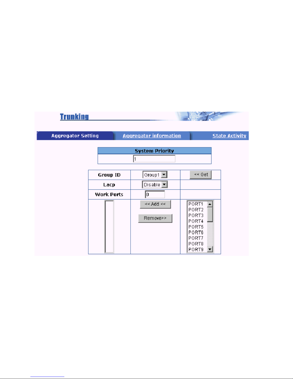
4.5 Trunking
The Link Aggregation Control Protocol (LACP) provides a standardized means for exchanging
information between Partner Systems on a link to allow their Link Aggregation Control instances to
reach agreement on the identity of the Link Aggregation Group to which the link belongs, move the link
to that Link Aggregation Group, and enable its transmission and reception functions in an orderly
manner. In conclusion, Link aggregation lets you group up to eight consecutive ports into a single dedicated connection. This feature can expand bandwidth to a device on the network. LACP operation
requires
full-duplex mode, more detail information refers to IEEE 802.3ad.
4.5.1 Aggregator setting
System Priority: A value used to identify the active LACP. The switch with the lowest value has the
highest priority and is selected as the active LACP.
1.Group ID: There are seven trunk groups to provided configure. Choose the group id and click
Get.
2.LACP: If enable, the group is LACP static trunking group. If disable, the group is local static trunking
group. All ports support LACP dynamic trunking group. If connecting to the device that also supports
LACP, the LACP dynamic trunking group will be created automatically.
'
Page 25
3. Work ports: Allow max four ports can be aggregated at the same time. If LACP static trunking
group, the exceed ports is standby and able to aggregate if work ports fail. If local static trunking group,
the number must be as same as the group member ports.
4 Select the ports to join the trunking group. Allow max four ports can be aggregated at the same time.
5. If LACP enable, you can configure LACP Active/Passive status in each ports on State Activity page.
6. Click Apply.
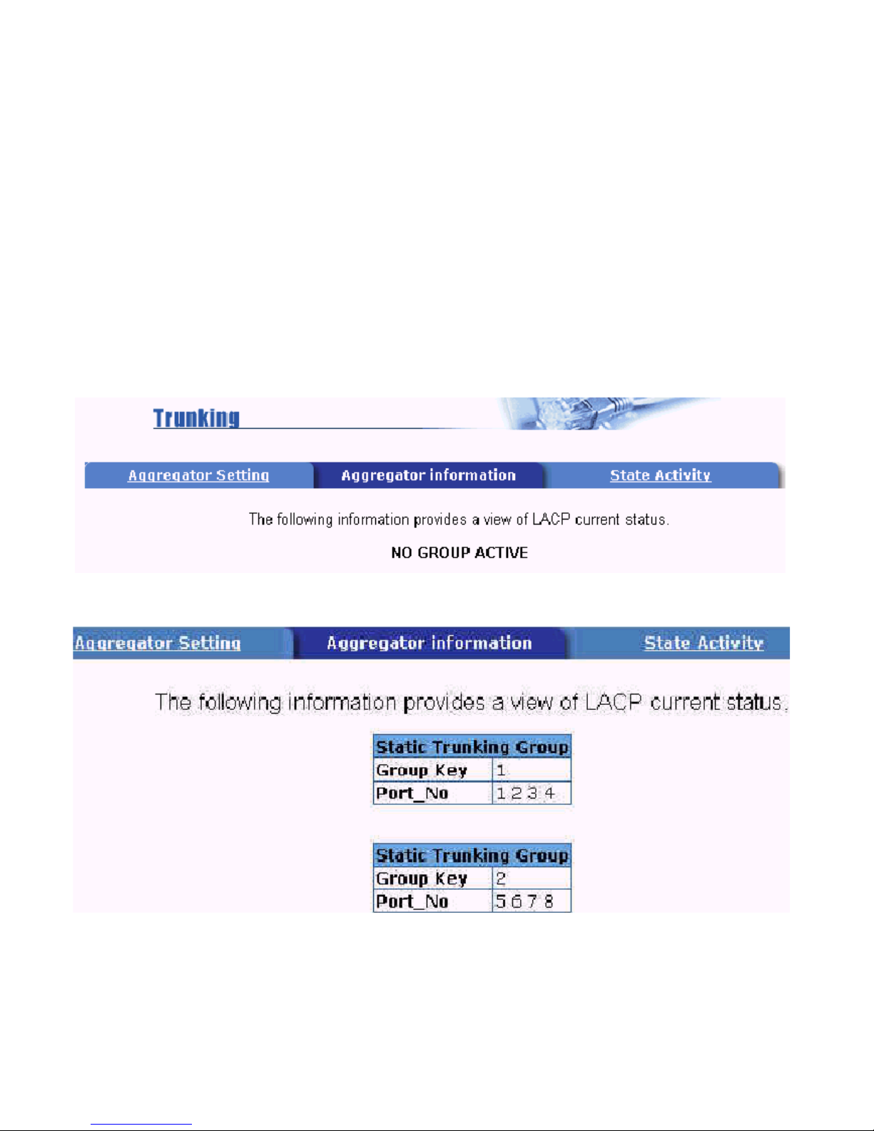
4.5.2 Aggregator Information
When you are setting LACP aggregator, you can see relation information here.
1. This page is no group active. LACP dont working.
2. This page is Static Trunking group.
Page 26
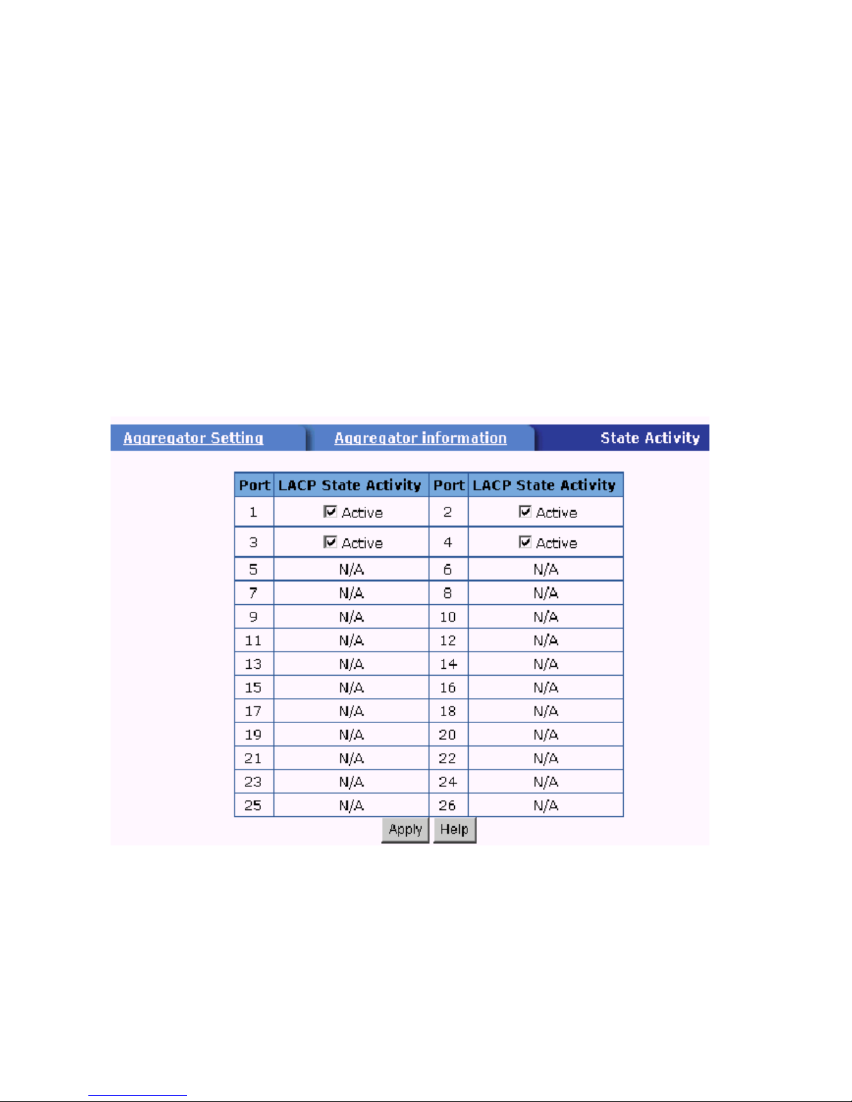
4.5.3 State Activity
Active (selected): The port automatically sends LACP protocol packets.
Passive (not selected): The port does not automatically sends LACP protocol packets, and responds
only if it receives LACP protocol packets from the opposite device.
1. A link having either two active LACP ports or one active port can perform dynamic LACP trunking.
A link has two passive LACP ports will not perform dynamic LACP trunking because
both ports are waiting for LACP protocol packets from the opposite device.
2. If you are active LACP actor, when you select trunking port, the active status will be created
automatically.
Page 27
4.6 Filter Database
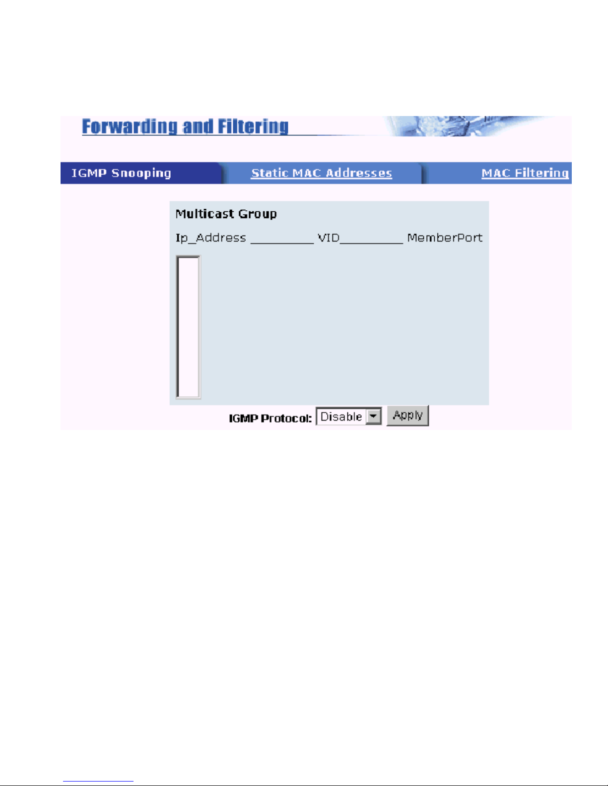
4.6.1 IGMP Snooping
This switch supports IP multicast, you can enable IGMP protocol on web managements switch
settings advanced page,then display the IGMP snooping information in this page, you can view difference multicast group ,VID and member port here, IP multicast addresses range from 224.0.0.0 through
239.255.255.255.
The Internet Group Management Protocol (IGMP) is an internal protocol of the Internet Protocol (IP)
suite. IP manages multicast traffic by using switches, routers, and hosts that support IGMP. Enabling
IGMP allows the ports to detect IGMP queries and report packets and manage IP multicast traffic
through the switch.
4.6.2 Static MAC Address
When you add a static MAC address, it remains in the switchs address table, regardless of whether
the device is physically connected to the switch or not. This saves the switch from having to re-learn a
devices MAC address when the disconnected or powered-off device is active on the network
again.
Page 28
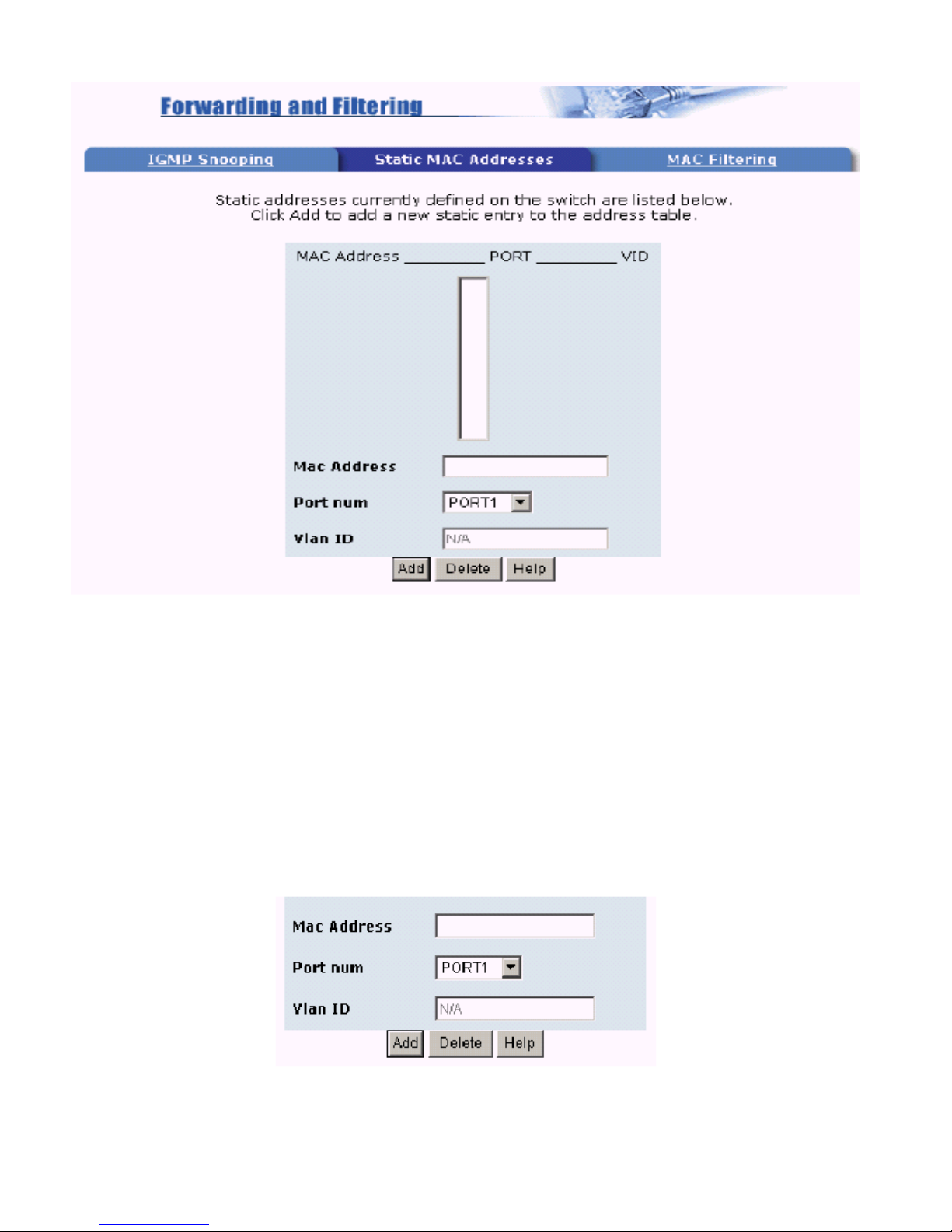
Steps to add Static MAC Address:
1. From the main menu, click administrator->Filter Database->Static MAC Address.
2. In the MAC address box, enter the MAC address to and from which the port should permanently
forward traffic, regardless of the devices network activity.
4. In the Port Number box, enter a port number.
5. If tag-based (IEEE 802.1Q) VLANs are set up on the switch, static addresses are associated with
individual VLANs. Type the VID (tag-based VLANs) to associate with the MAC address.
6. Click add.
!
Page 29
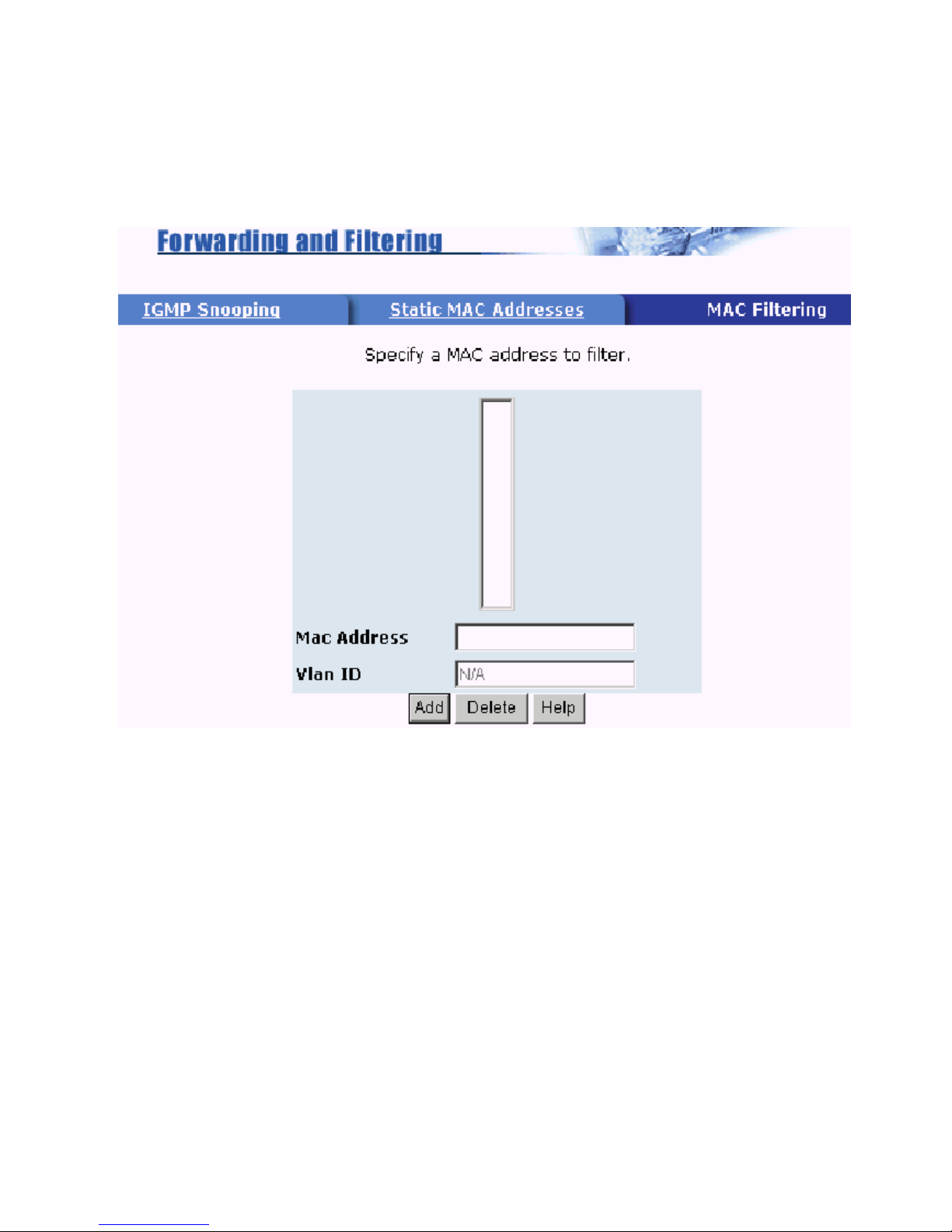
4.6.3 MAC Filtering
MAC address filtering allows the switch to drop unwanted traffic. Traffic is filtered based on the
destination addresses.
Steps to specify a MAC address to filter:
1.In the MAC Address box, enter the MAC address that wants to filter.
2. If tag-based (802.1Q) VLAN are set up on the switch, in the VLAN ID box, type the VID to
associate with the MAC address.
3. Click the Add.
4. Choose the MAC address that you want to delete and then click the Delete can delete it.
"
Page 30
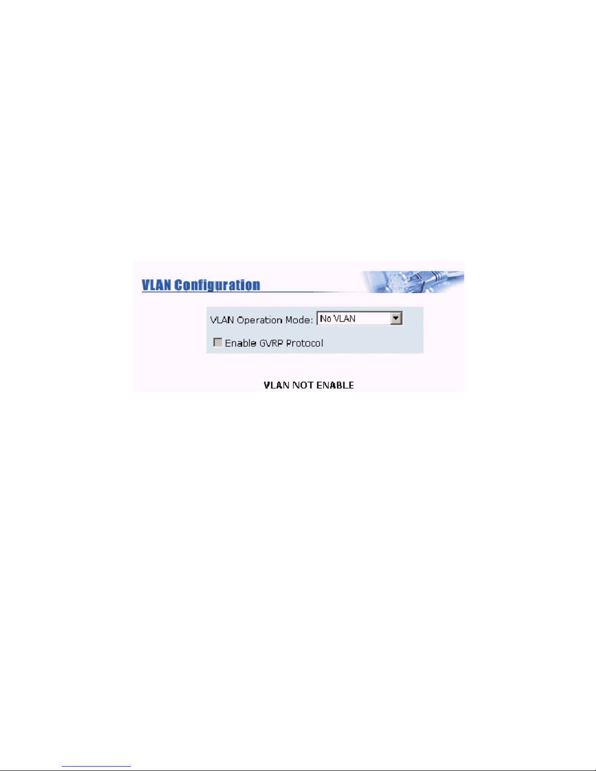
4.7 VLAN Configuration
A Virtual LAN (VLAN) is a logical network group that limits the broadcast domain. It allows you to
isolate network traffic so only members of the VLAN receive traffic from the same VLAN members.
Basically, creating a VLAN from a switch is logically equivalent of reconnecting a group of network
devices to another Layer 2 switch. However, all the network devices are still plug into the same switch
physically.
This switch supports both port-based and 802.1Q (tagged-based) VLAN in web management page.
In the default configuration, VLAN support is disabled.
NOTE: You have to reboot the switch for valid value every time you change the VLAN mode.
#
Page 31
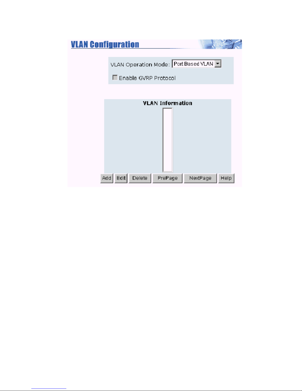
4.7.1 Port-based VLAN
Steps to create a new VLAN group based on port-based VLAN:
1.Click Add to create a new VLAN group.
2.Enter the VLAN name, group ID and select the members for the new VLAN.
3.Click Apply.
4.If there are many groups that over the limit of one page, you can click the NextPage to view other
VLAN groups.
NOTE: If the trunk group exists, you can see it (ex: TRK1,TRK2...) in select menu of ports, and you
can configure it as the member of the VLAN or not.
$
Page 32
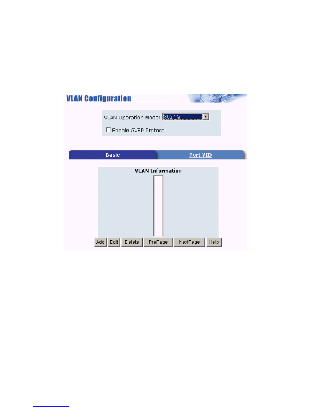
4.7.2 802.1Q VLAN
In this page, you can create Tag-based VLAN, and enable or disable GVRP protocol. There are 256
VLAN groups to configure. Enable 802.1Q VLAN, the all ports on the switch belong to default
VLAN, VID is 1. The default VLAN cant be deleted.
GVRP (GARP [Generic Attribute Registration Protocol] VLAN Registration Protocol) GVRP allows
automatic VLAN configuration between the switch and nodes. If the switch is connected to a device
with GVRP enabled, you can send a GVRP request using the VID of a VLAN defined on the switch,
then it will automatically add that device to the existing VLAN.
%
Page 33
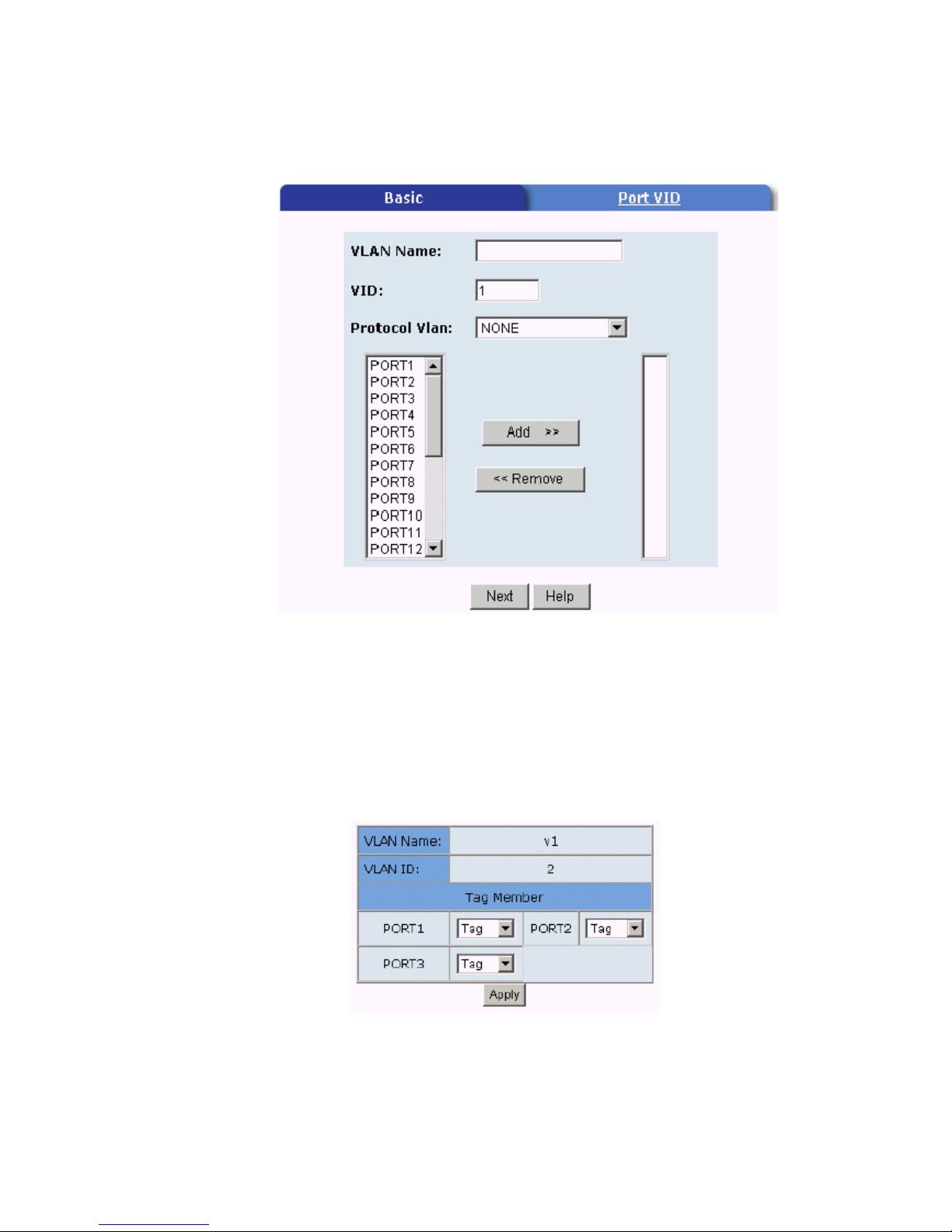
4.7.3 Basic
Create a VLAN and add tagged member ports to it.
1. From the main menu, click administrator-> VLAN configuration, click Add then you will see the
page as follow.
2. Type a name for the new VLAN.
3. Type a VID (between 2-4094). The default is 1.
4. Choose the protocol type.
5. From the Available ports box, select ports to add to the VLAN and click Add >>. If the trunk
group exists, you can see it here (ex: TRK1,TRK2), and you can configure it as the member of the
VLAN or not.
6. Click Next. Then you can view the page as follow.
7. Use this page to set the outgoing frames as VLAN-Taggedframes or no. Then click Apply.
Tag: outgoing frames with VLAN-Tagged.
Untag: outgoing frames without VLAN-Tagged.
&
Page 34
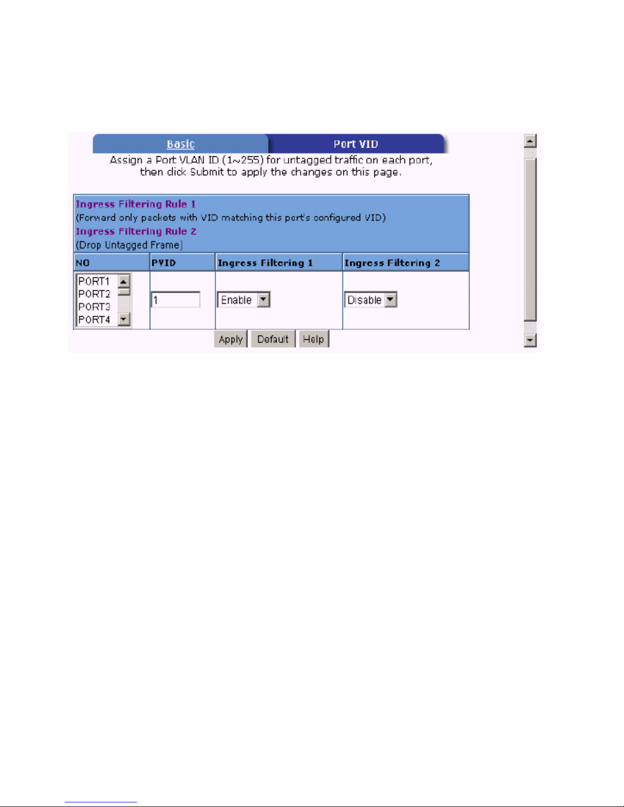
4.7.4 Port VID
Configure port VID settings
From the main Tag-based (IEEE 802.1Q) VLAN page, click Port VID Settings.
Port VID (PVID)
Set the port VLAN ID that will be assigned to untagged traffic on a given port. This feature is useful
for accommodating devices that you want to participate in the VLAN but that dont support tagging.
Each port of this switch allows user to set one PVID, the range is 1~255, default PVID is 1. The PVID
must be the same as the VLAN ID the port belongs to, or the untagged traffic will be dropped.
Ingress Filtering
Ingress filtering lets frames belonging to a specific VLAN to be forwarded if the port belongs to that
VLAN. This switch have two ingress filtering rule as follows:
Ingress Filtering Rule 1: Forward only packets with VID matching this ports configured VID.
Ingress Filtering Rule 2: Drop Untagged Frame.
'
Page 35
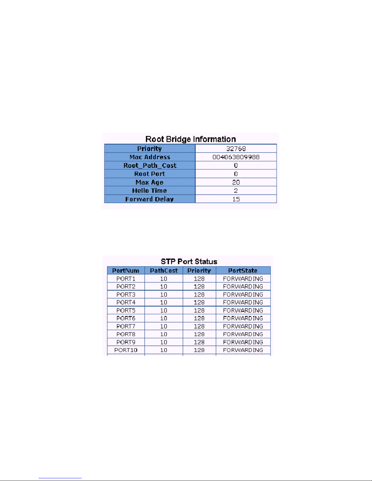
4.8 Spanning Tree
The Spanning-Tree Protocol (STP) is a standardized method (IEEE 802.1D ) for avoiding loops in
switched networks. When STP enabled, ensure that only one path at a time is active between any two
nodes on the network.
You can enable Spanning-Tree Protocol on web managements switch setting advanced item by
selecting enable Spanning-Tree protocol. We are recommended that you enable STP on all switches
ensures a single active path on the network.
1.You can view spanning tree information about the Root Bridge, such as following screen.
2.You can view spanning tree status about the switch, such as following screen.
3. You can set new value for STP parameter, then click Apply button to modify.
!
Page 36
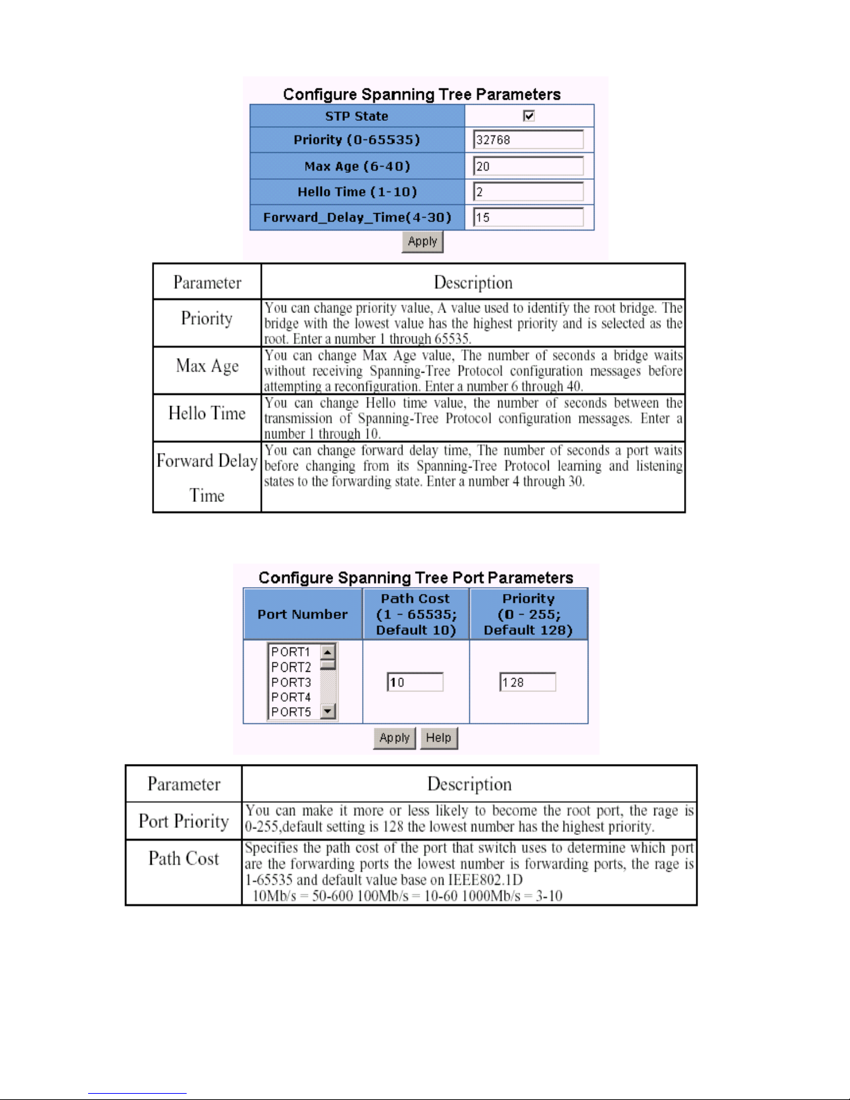
4. The following parameter can be configured on each port,click Apply button to modify.
!
Page 37
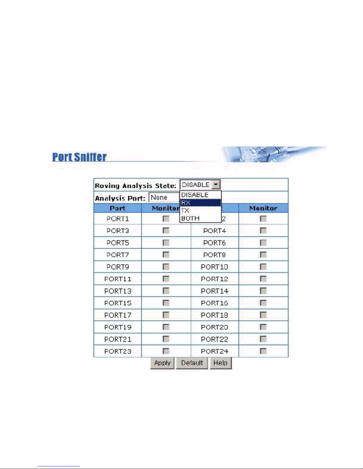
4.9 Port Sniffer
The Port Sniffer is a method for monitor traffic in switched networks. Traffic through ports can be
monitored by one specific port. That is, traffic goes in or out monitored ports will be duplicated into
sniffer port.
1.Roving Analysis State: Press Space key to set sniffer mode as Disable, Rx, Tx or Both.
2.Analysis Port: It means sniffer port which can be used to see all monitored port traffic.
You can connect analysis port to Lan analysier or netxray.
3.Monitored Port: The ports you want to monitor. All monitor ports traffic will be copied to analysis
port. You can select max 25 monitor ports in the switch. You can choose which port want to be monitored in only one sniffer mode.
!
Page 38
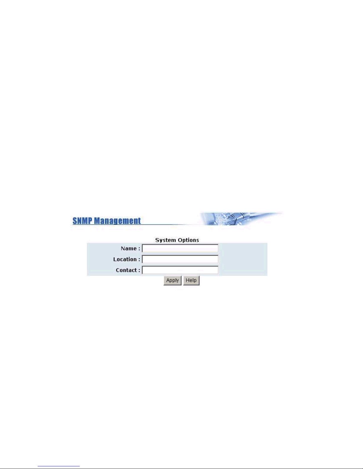
4.10 SNMP
Any Network Management running the simple Network Management Protocol (SNMP) can management the switch, provided the Management Information Base (MIB) is installed correctly on the management station. The SNMP is a Protocol that governs the transfer of information between management
and agent. This switch supports SNMP V1.
1. Use this page to define management stations as trap managers and to enter SNMP community
strings. You can also define a name, location, and contact person for the switch. Fill in the system
options data then click Apply to update the changes on this page.
Name: Enter a name to be used for the switch.
Location: Enter the location of the switch.
Contact: Enter the name of a person or organization.
!!
Page 39
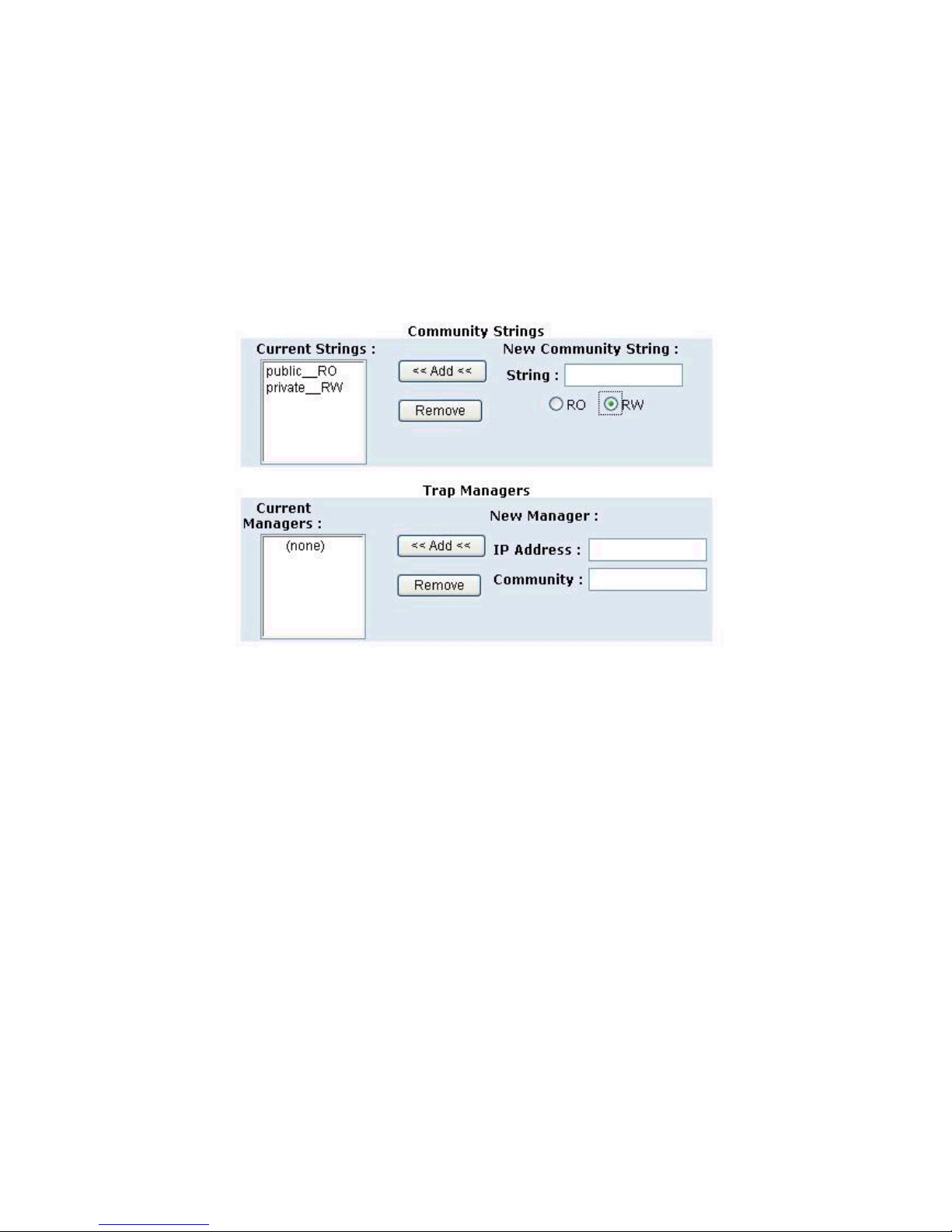
2. Community strings serve as passwords and can be entered as one of the following:
RO: Read only. Enables requests accompanied by this string to display MIB-object information.
RW: Read write. Enables requests accompanied by this string to display MIB-object information and to
set MIB objects.
3. Trap Manager
A trap manager is a management station that receives traps, the system alerts generated by the switch.
If no trap manager is defined, no traps are issued. Create a trap manager by entering the IP address of
the station and a community string.
!"
Page 40
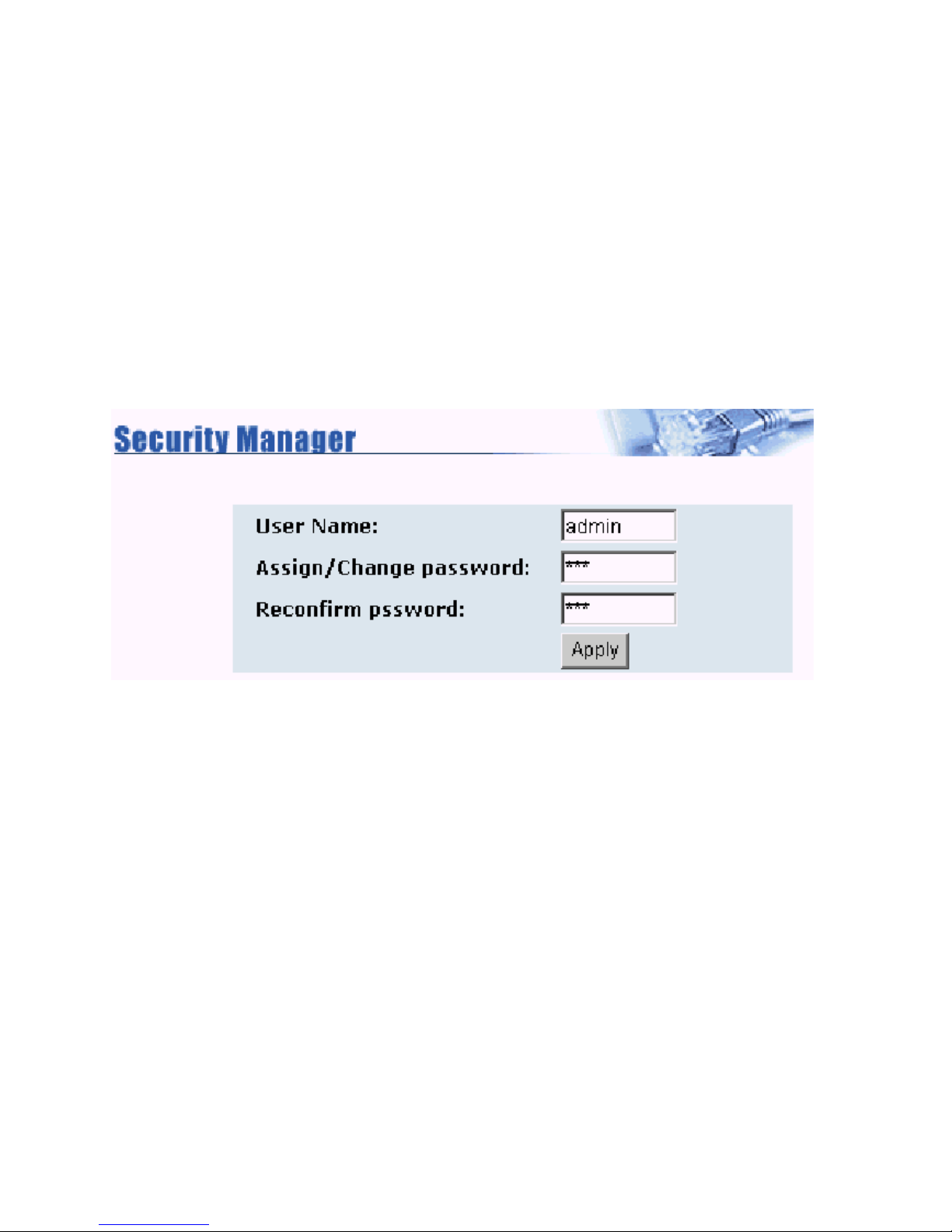
4.11 Security Manager
Use this page you can change web management user name and password.
1.User name: Type the new user name.
2. Password: Type the new password.
3. Reconfirm password: Retype the new password.
4. Click Apply.
!#
Page 41
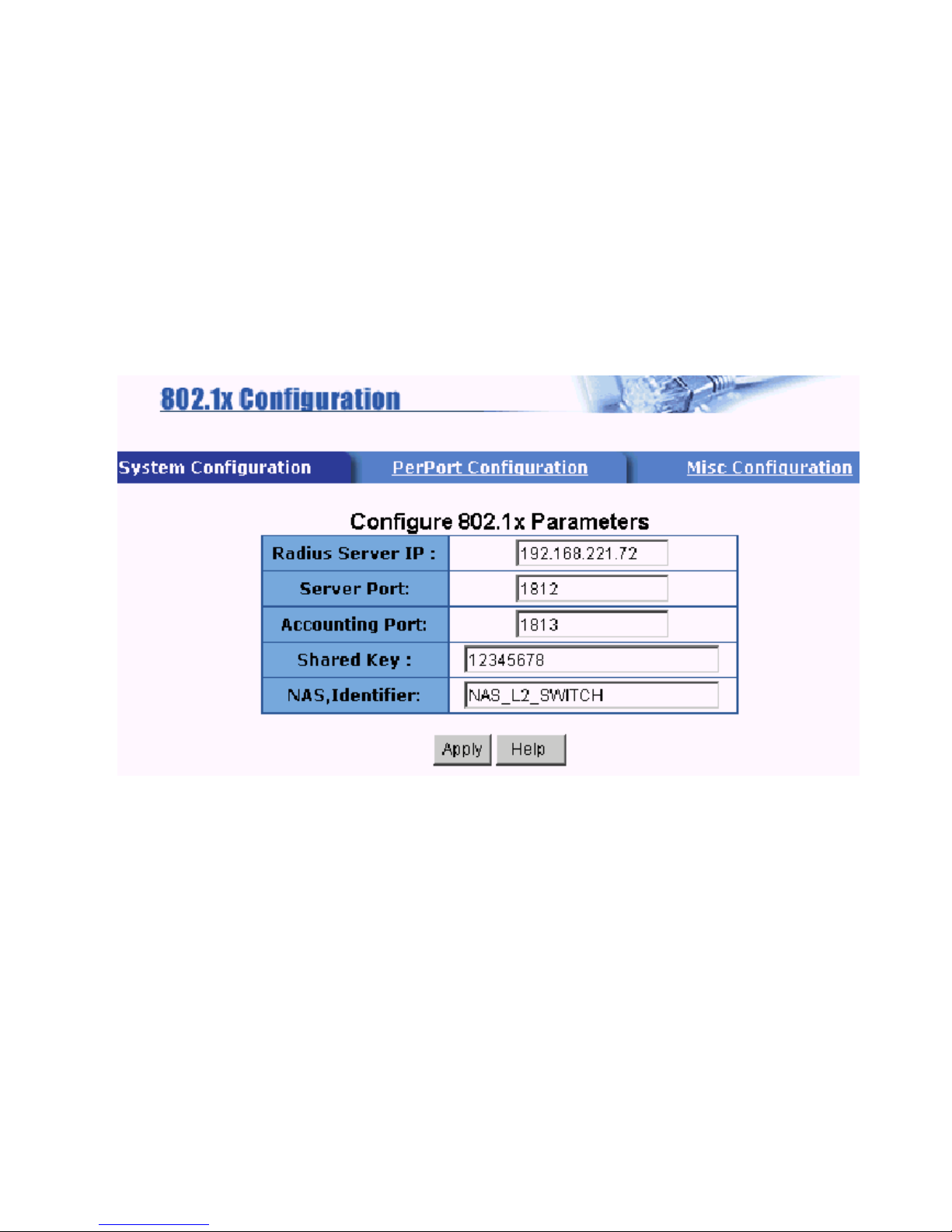
4.12 802.1X Configuration
If you enable the IEEE 802.1X function, you can configure the parameters of this function.
System Configuration
1. Radius Server IP: Set the Radius Server IP address
2. Server Port: Set the UDP destination port for authentication requests to the specified Radius Server.
3. Accounting Port: Set the UDP destination port for accounting requests to the specified Radius
Server.
4. Shared Key: Set an encryption key for use during authentication sessions with the specified radius
server. This key must match the encryption key used on the Radius Server.
5. NAS, Identifier: Set the identifier for the radius client.
!$
Page 42
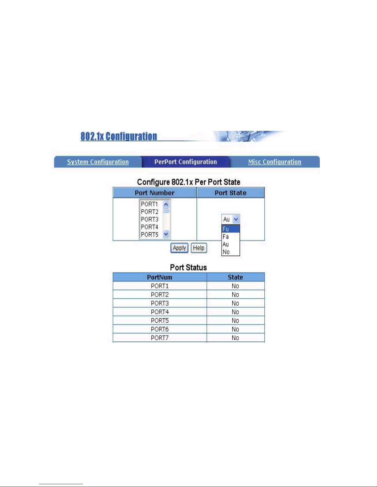
4.12.1 Perport Configuration:
There are four types for each port:
Fu, Force unauthorized: The specified port is required to be held in the Unauthorized state.
Fa, Force authorized: The specified port is required to be held in the Authorized state.
Au, Auto: The specified port is set to the Authorized or Unauthorized state in accordance with the
outcome of an authentication exchange between the Supplicant and the authentication server.
No, None: The specified port is required to be held in the Authorized state.
Page 43
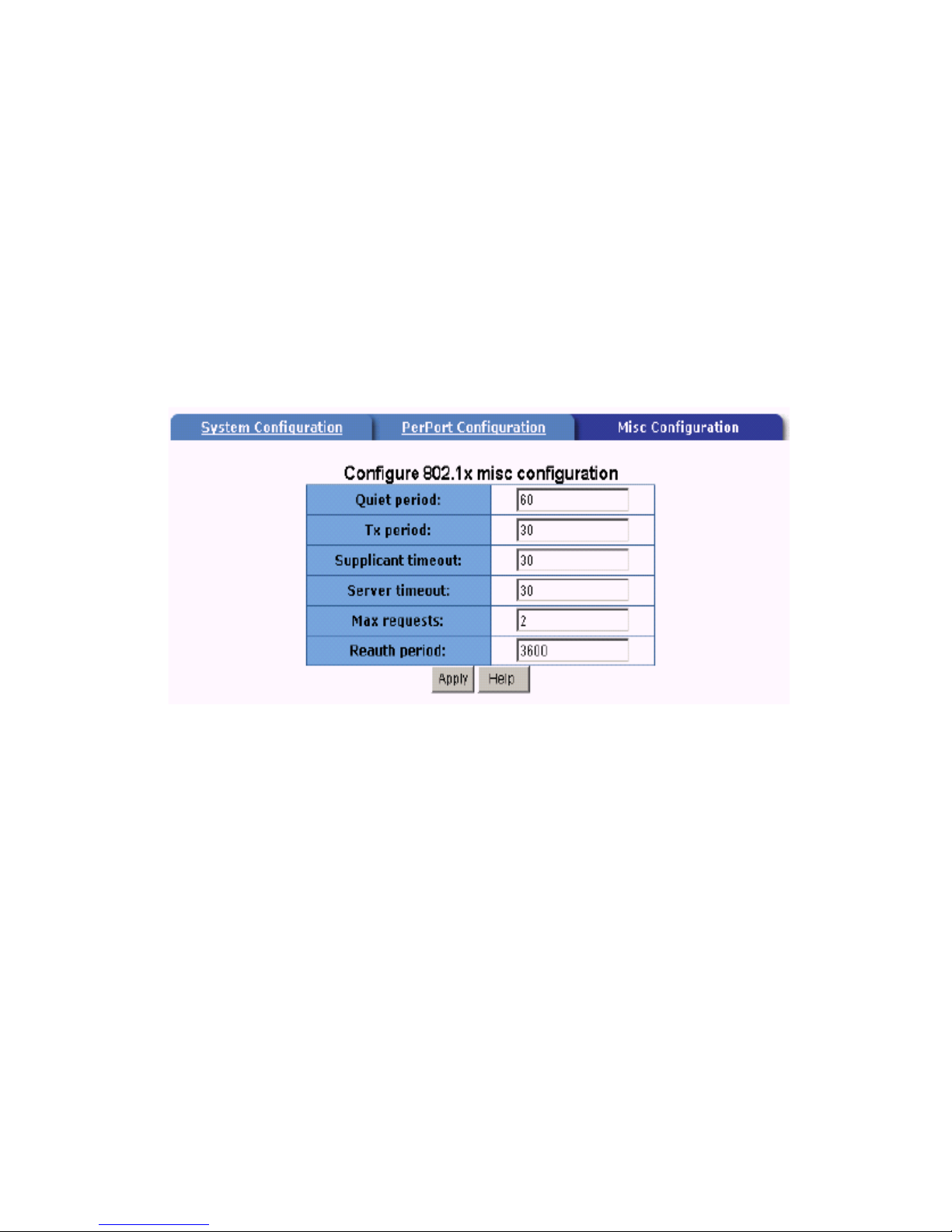
4.12.2 MISC Configuration
1. Quiet period: Set the period during which the port doesnt try to acquire a supplicant.
2. Tx period: Set the period the port waits to retransmit next EAPOL PDU during an authentication
session.
3. Supplicant timeout: Set the period of time the switch waits for a supplicant response to an EAP
request.
4. Server timeout: Set the period of time the switch waits for a server response to an authentication
request.
5. Max requests: Set the number of authentication attemps that must time-out before authentication fails
and the authentication session ends.
6. Reauth period: Set the period of time after which clients connected must be reauthenticated.
!&
Page 44
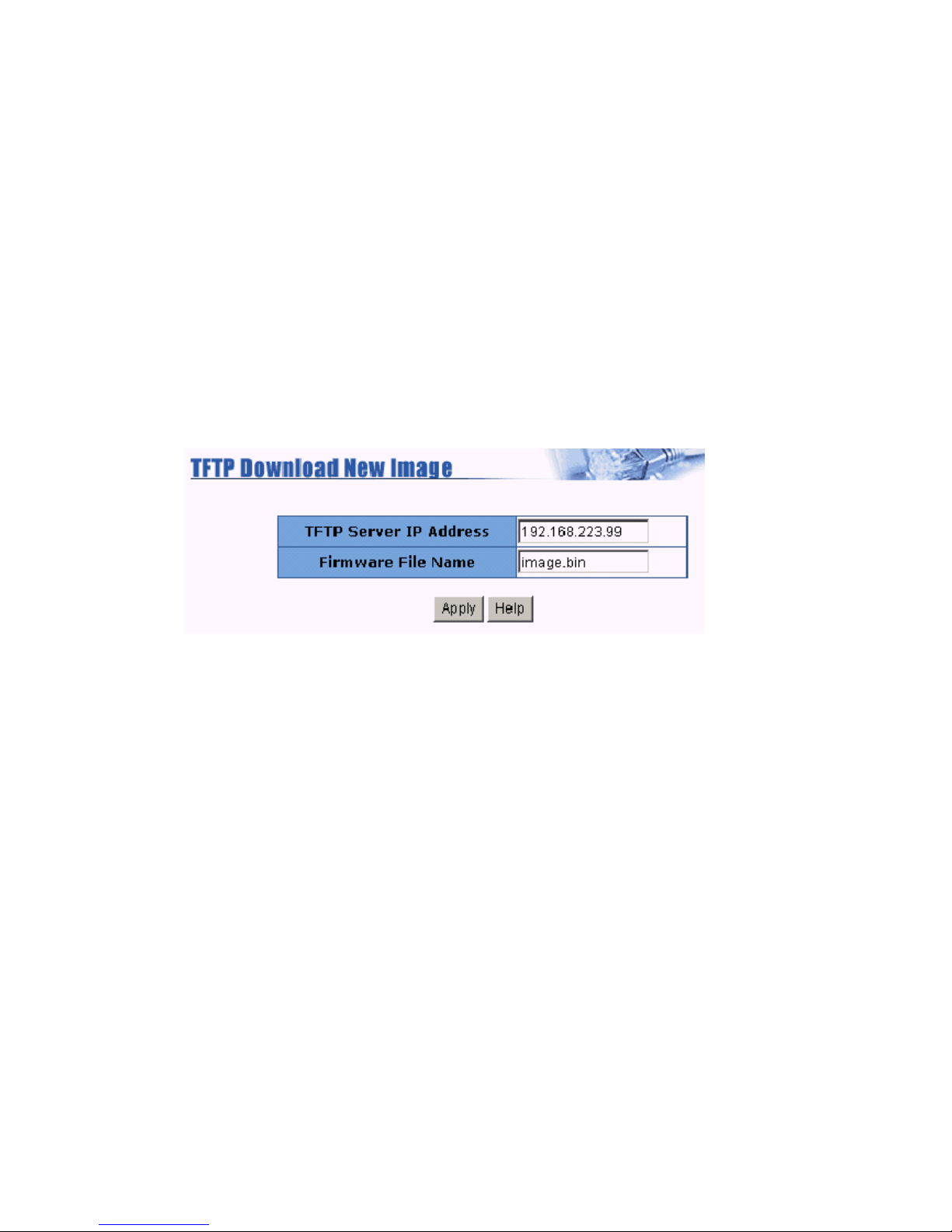
4.13 TFTP Update Firmware
The following menu options provide some system control functions to allow a user to update firmware
and remote boot switch system:
1. Install TFTP Turbo98 and execution.
2. Copy firmware update version image.bin to TFTP Turbo98 directory.
3. In web management select administratorTFTP update firmware.
4. Download new image.bin file then in web management press <update firmware>.
5. After update finished, press <reboot> to restart switch.
!'
Page 45
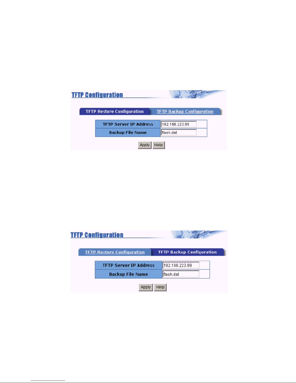
4.14 Configuration Backup
4.14.1 TFTP Restore Configuration
Use this page to set tftp server address. You can restore EEPROM value from here, but you must put
back image in tftp server, switch will download back flash image.
4.14.2 TFTP Backup Configuration
Use this page to set tftp server IP address. You can save current EEPROM value from here, then go
to the TFTP restore configuration page to restore the eeprom value.
"
Page 46
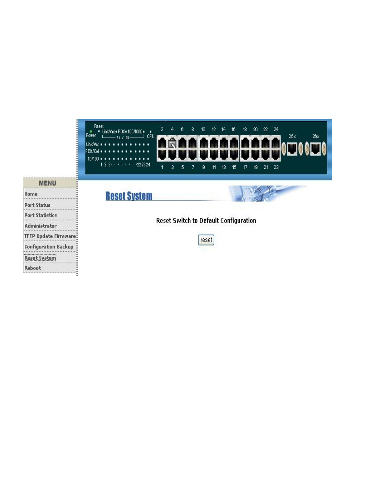
4.15 Reset System
Reset the Switch to default configuration, default value as below
"
Page 47
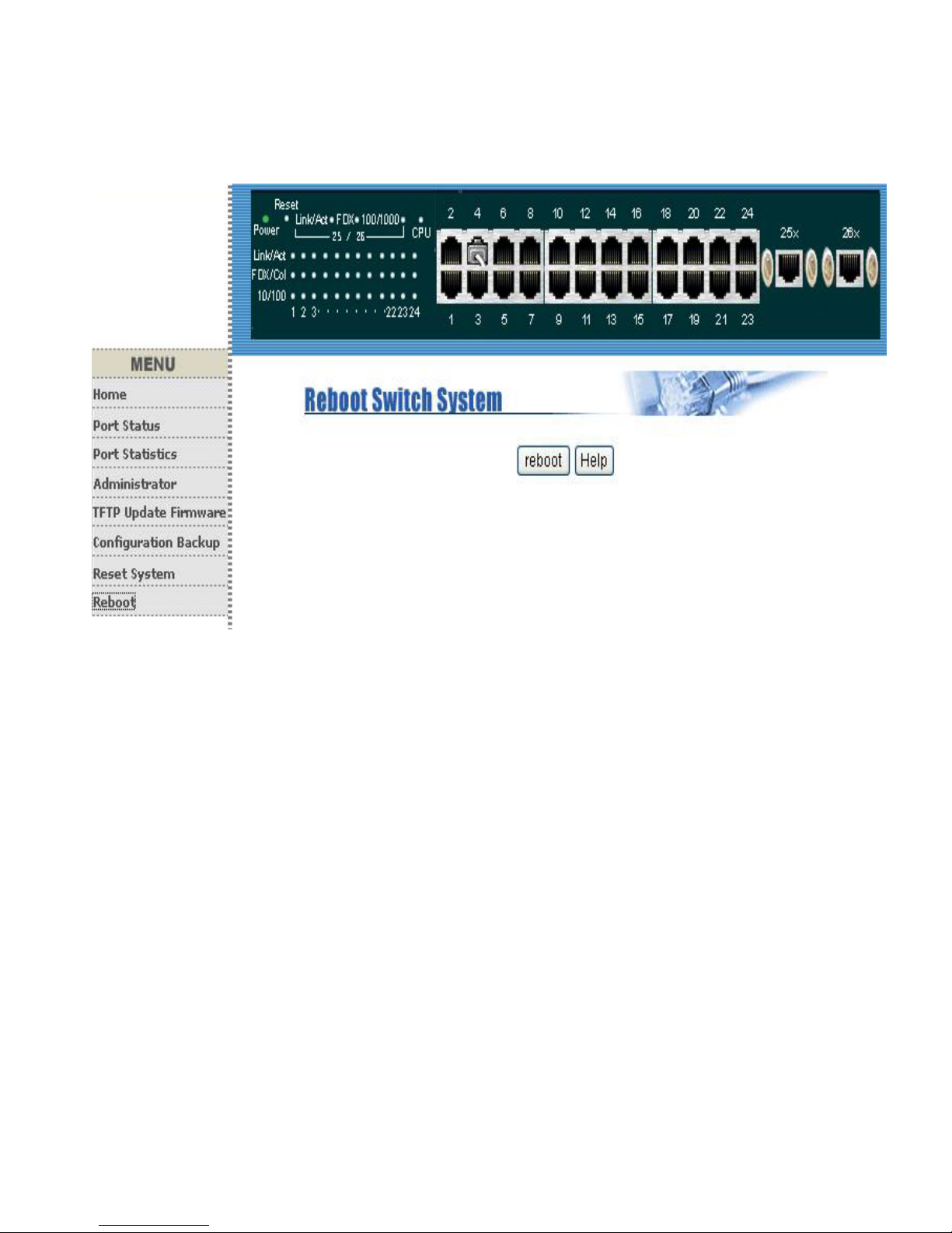
4.16 Reboot
Reboot the system in software reset.
"
Page 48
5.Configuration of Management Function
Before configuration
1.Connect to PC: Attach a RS-232 serial cable 9-pin male connector to the female
connector on the switch. Plug the other side of this cable to your PC.
2.Using Hyper Terminal to connect to Switch: In MS-Windows, launch Hyper
Terminal, create a new connection, and follow these steps:
(1) Open the HyperTerminal application.
(2) In Windows, select run from the start menu and choose the application.
(3) From the HyperTerminal menu, double click the icon then on the next window;
create a new name, such as 24+2G Smart Switch.
(4)Adjust the settings of the communication port. Select the using by connect interface
such as COM1, COM2. Then select the Bits per second at 9600 and set the flow
control value as None.
"!
Page 49

6. Console-Menu Line
This switch also provides a serial interface to manage and monitor, you can follow the Console Port
Information provided by web to use windows HyperTerminal program to link the switch.
You can type user name and password to login. The default user name is admin with password
123.
""
Page 50
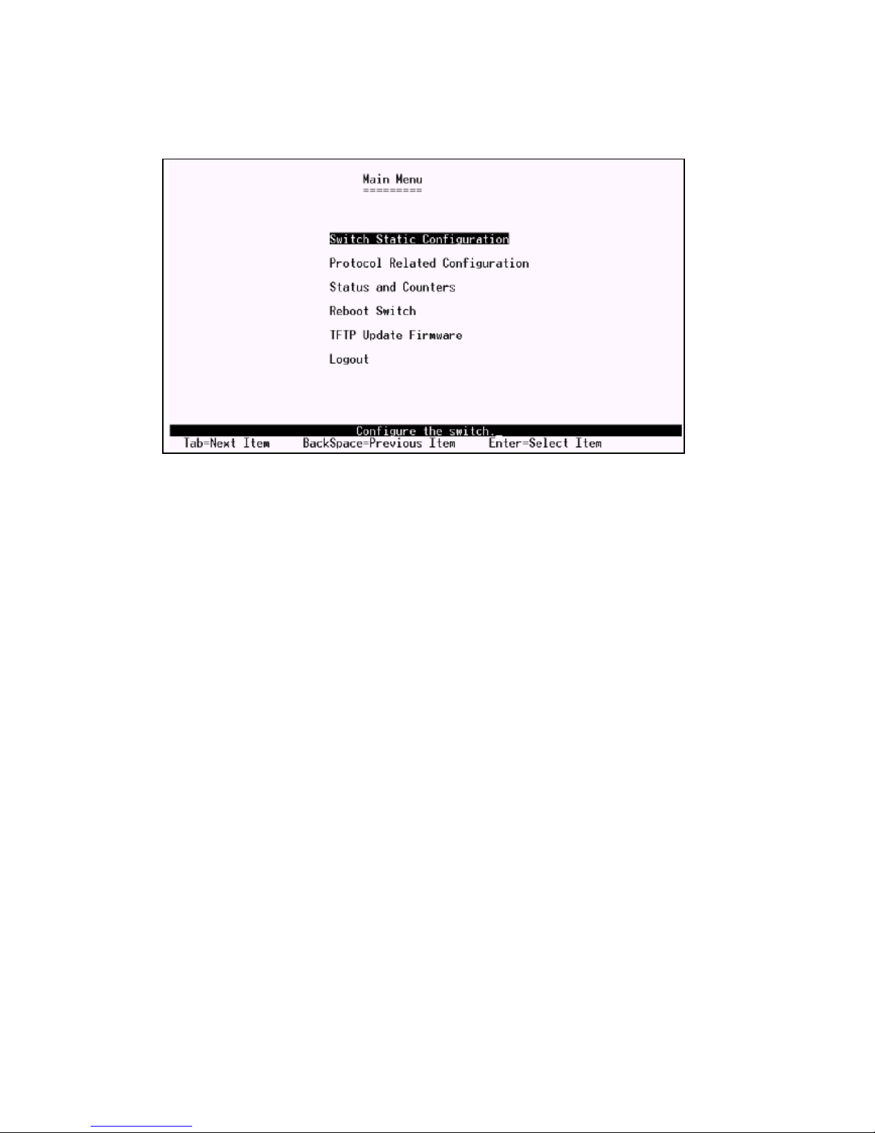
6.1 Main Menu
There are six items for selected as follows:
Switch Static Configuration: Configure the switch.
Protocol Related Configuration: Configure the protocol function.
Status and Counters: Show the status of the switch.
Reboot Switch: Restart the system or reset switch to default configuration.
TFTP Update Firmware: Use tftp to download image.
Logout: Exit the menu line program.
<Control Key> The control keys as follow provided in all menus:
Ta b: Move the vernier to next item.
Backspace: Move the vernier to previous item.
Enter: Select item.
Space: Toggle selected item to next configure.
"#
Page 51
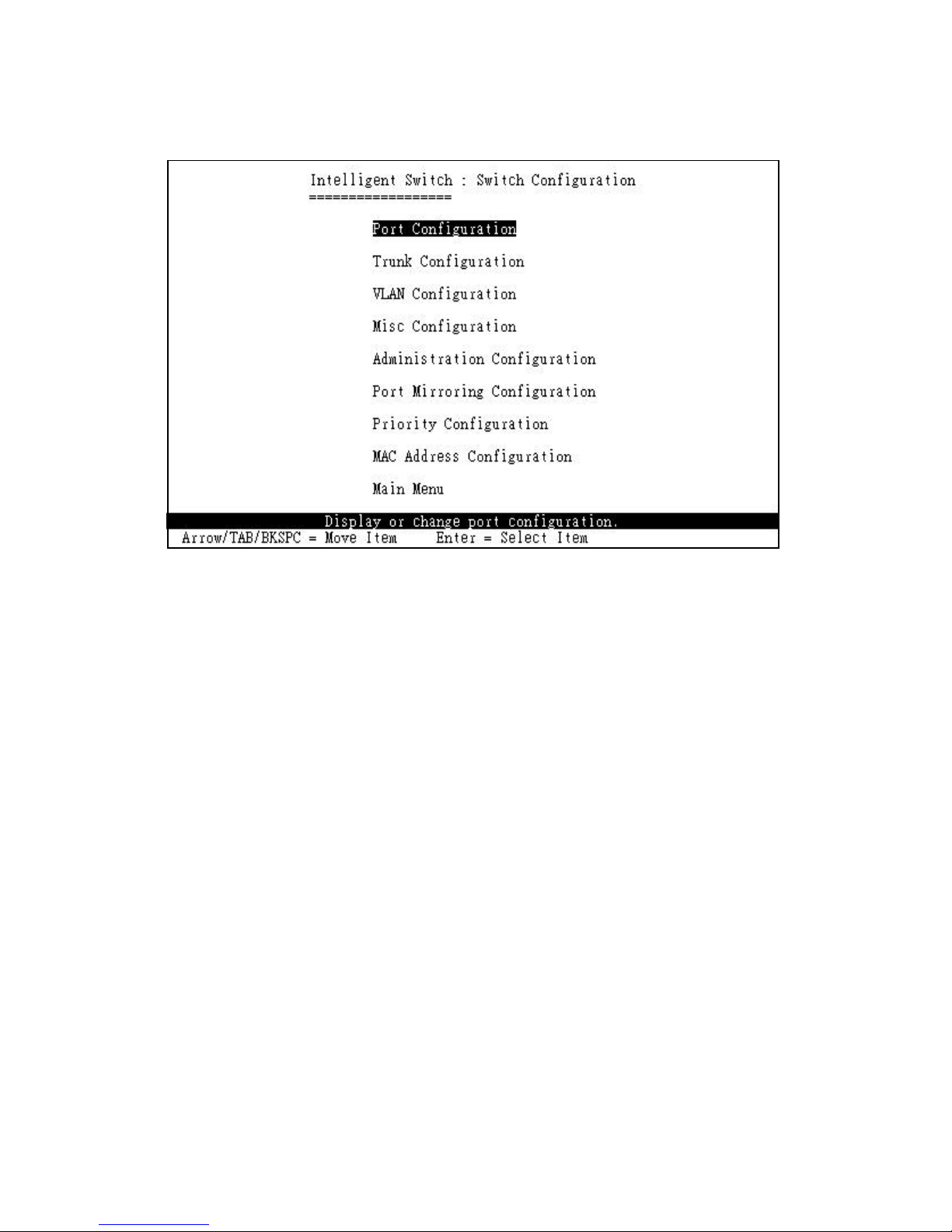
6.2 Switch Static Configuration
You can press the key of Tab or Backspace to choose item, and press Enter key to select item. The
action menu line as follow provided in later configure page.
Actions->
<Quit>: Exit the page of port configuration and return to previous menu.
<Edit>: Configure all items. Finished configure press Ctrl+A to go back action menu line.
<Save>: Save all configure value.
<Previous Page>: Return to previous page to configure.
<Next page>: Go to next page to configure.
"$
Page 52
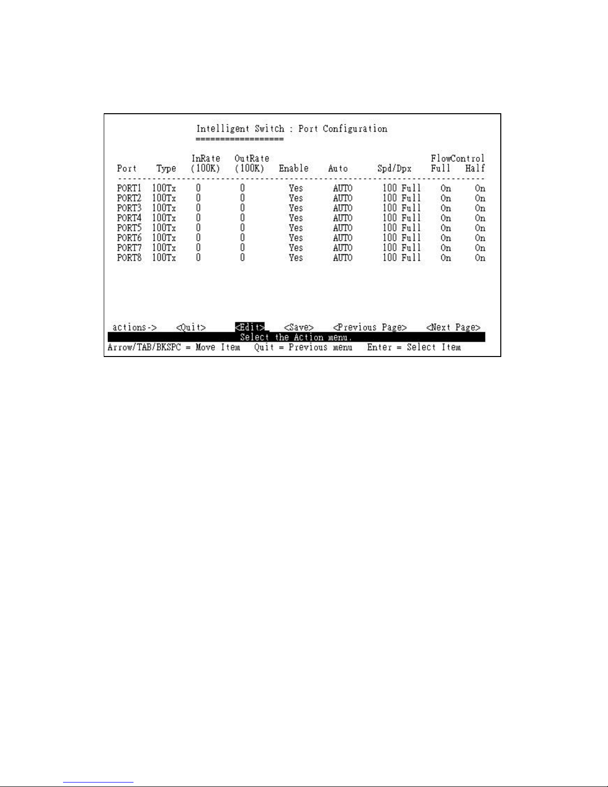
6.2.1 Port Configuration
This page can change the status of each port. Press <Space> key to change configuration of each
item.
1. InRate(100K/unit): You can set input rate control, per unit is 100K. The valid range is 0~1000.
0: disable rate control.
1~1000: valid rate value.
2. OutRate(100K/unit): You can set output rate control, per unit is 100K. The valid range is 0~1000.
0: disable rate control.
1~1000: valid rate value.
3.Enable: You can disable or enable this port control. Yes means the port is enabled, No means
the port is disabled.
4.Auto: You can set auto-negotiation mode as Auto, Nway_Force or Force of each port.
5.Spd/Dpx: You can set 100/10Mbps speed on port 1~port24; 1000/100/10Mbps speed on
port25~port26 (Gigabit Switch), 100/10Mbps speed on port25~port26 (Fast Ethernet Switch)
and set full-duplex or half-duplex mode.
6. Flow Control:
Full: Displays the flow control status is enable/disable in full duplex mode.
"%
Page 53

Half: Displays the backpressure is enable/disable in half duplex mode.
NOTE:
1. Pressing <Save> only can save one page configuration.
2. If the static trunk group exists, you can see it (ex: TRK1, TRK2) after port 26, and you can
configure all of the items
as above.
"&
Page 54
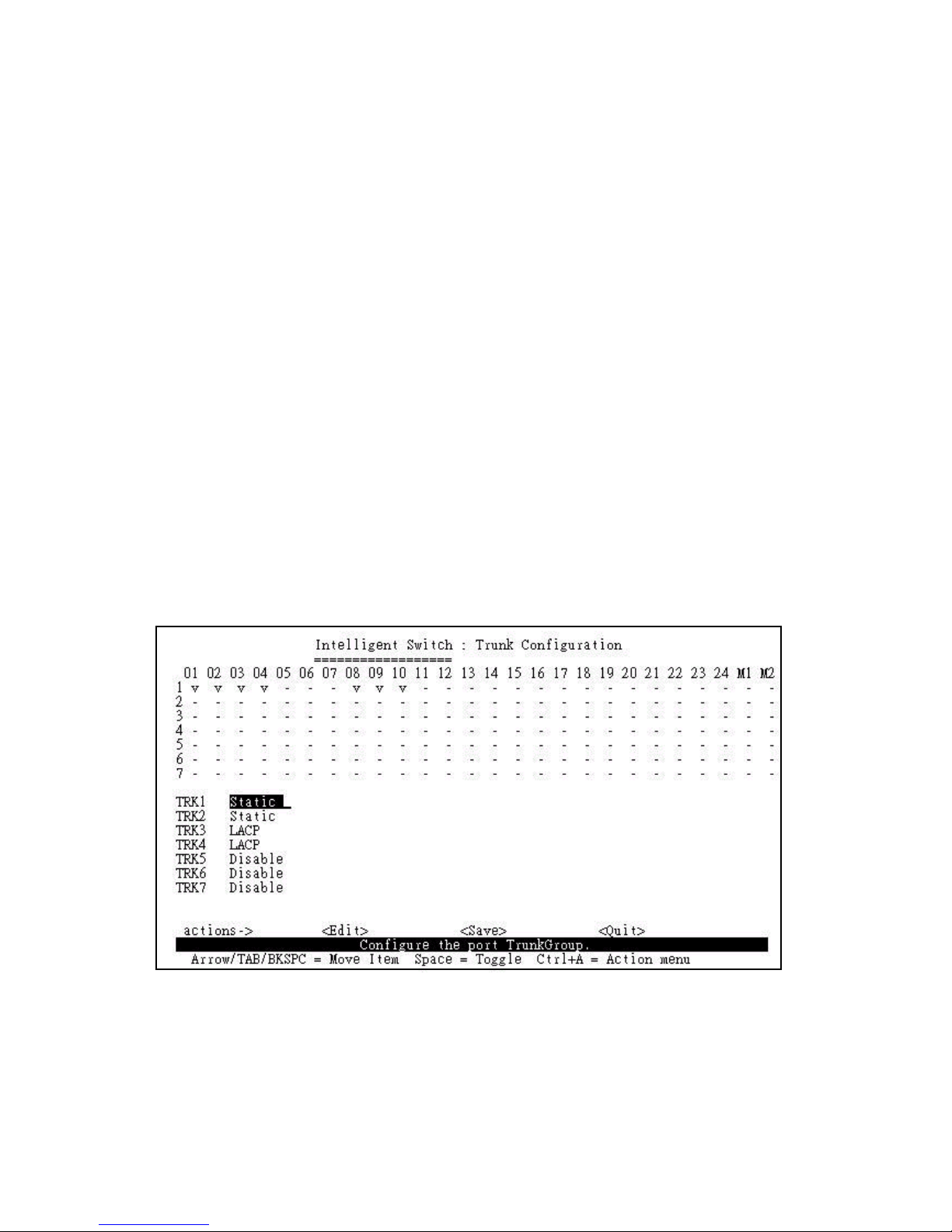
6.2.2 Trunk Configuration
This page can create max to seven trunk groups. You can arbitrarily select up to four ports from port
1~port 24/port25 ~ port26 to build a trunking group.
1. Select <Edit> on actions menu.
2. Press <Space> key to configure the member port of the trunk group. Besides, you have to set
Static or LACP for the corresponding trunk group of TRK1~TRK7 item.
Static the normal trunk.
LACP this trunk group have link aggregation control protocol.
3. Press Ctrl+A to go back action menu line.
4. Select <Save> to save all configure value.
5. If the item of TRK1~TRK7 is set Disable, it means the trunk group is deleted.
6. All ports in the same static trunk group will be treated as single port. So when you setting VLAN
members and Port configuration they will be toggled on or off simultaneously.
NOTE: If VLAN group exists, all of the members of static trunk group must be in same VLAN group.
"'
Page 55
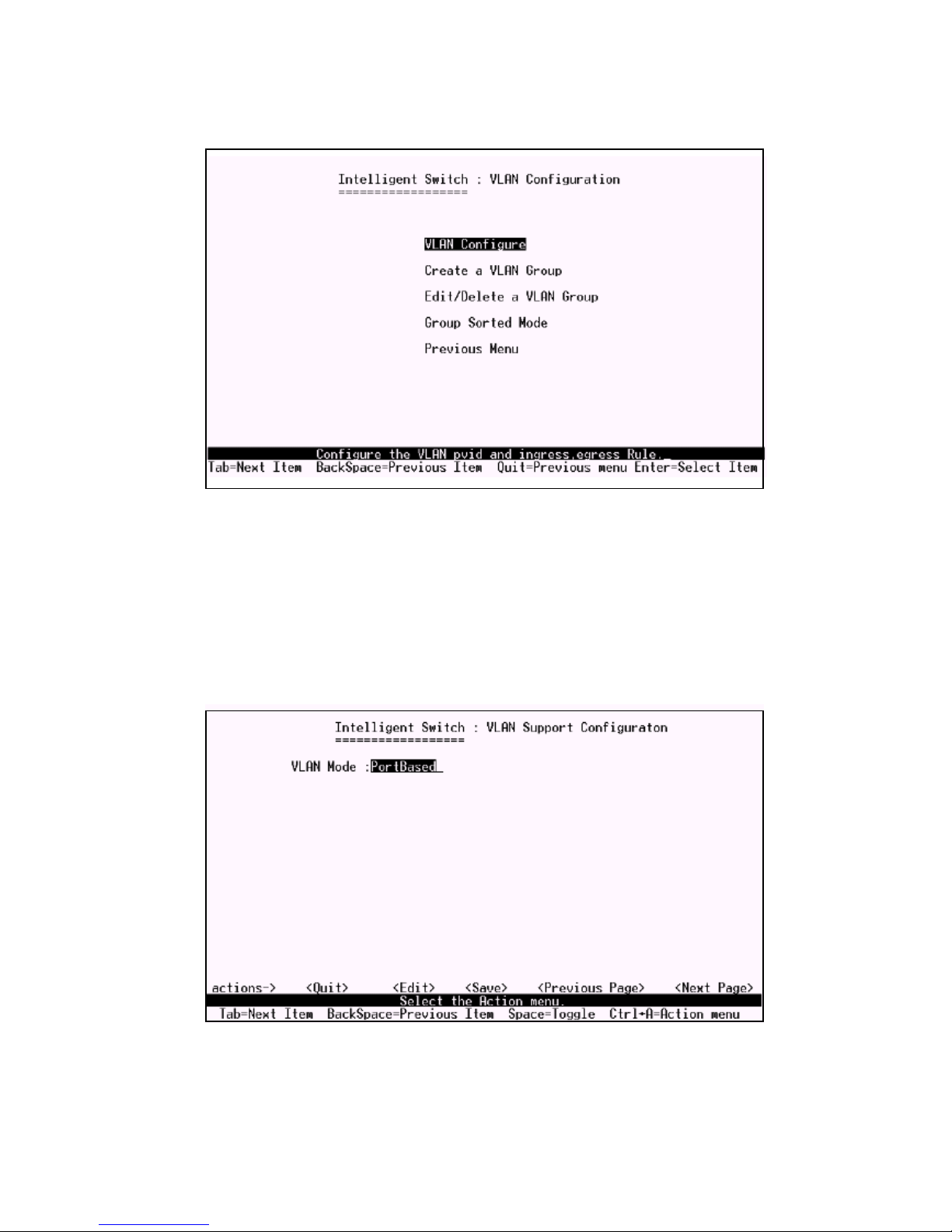
6.2.3 VLAN Configuration
This page can set VLAN mode as port-based VLAN, 802.1Q VLAN or just disable the VLAN
function.
NOTE: You have to restart the switch for valid value every time, you change the VLAN mode.
#
Page 56
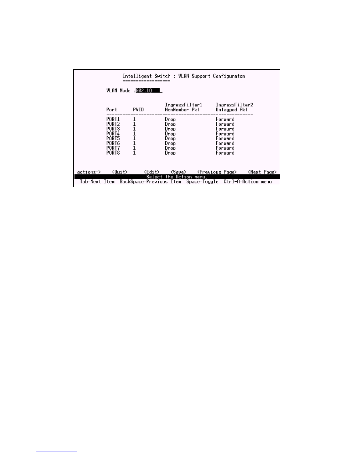
If set 802.1Q VLAN, you can set PVID, ingress filtering 1 and ingress filtering 2 in this page too.
1.PVID (Port VID : 1~255): Type the PVID.
2.NonMember Pkt: It matches that Ingress Filtering Rule 1 on web management. It will forward only
packets with VID matching this ports configured VID. Press Space key to choose forward or drop the
frame that VID not matching this ports configured VID.
3.UnTagged Pkt: It matches that Ingress Filtering Rule 2 on web management. It will drop untagged
frames. Press Space key to choose drop or forward the untagged frames.
#
Page 57
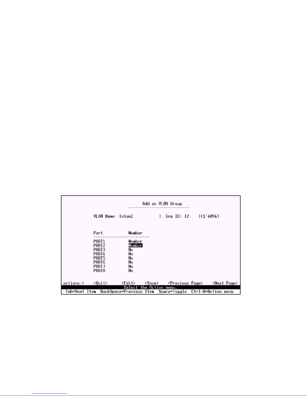
6.2.3.1 Create a VLAN Group
Create Port-based VLAN and add member/nonmember ports to it
1.Select <Edit>.
2.VLAN Name: Type a name for the new VLAN.
3.Grp ID: Type the VLAN group ID. The group ID range is 1~26.
4.Member: Press Space key to choose VLAN member.
There are two types to select:
a. Member: the port is a member port.
b. NO: the port is NOT a member port.
5.Press Ctrl+A go back action menu line.
6.Select <Save> to save all configure value.
NOTE: If the trunk group exists, you can see it (ex: TRK1, TRK2) after port26, and you can
configure it is the member of the VLAN or not.
#
Page 58
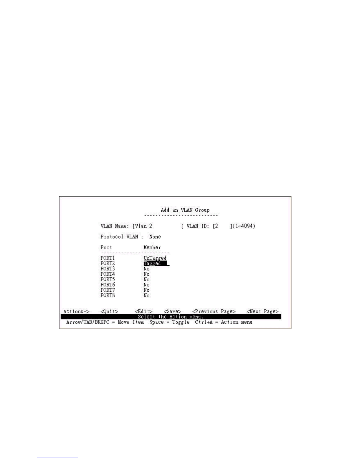
Create 802.1Q VLAN and add tagged /untagged member ports to it
1.Select <Edit>.
2.VLAN Name: Type a name for the new VLAN.
3.VLAN ID: Type a VID (between 2~4094). The default is 1.
There are 256 VLAN groups to configure.
3.Protocol VLAN: Press Space key to choose protocol types.
4.Member: Press Space key to choose VLAN members. There are three types to select:
UnTagged: this port is the member port of this VLAN group and outgoing frames are NO VLAN-
Tagged frames.
Tagged: this port is the member port of this VLAN group and outgoing frames are VLAN-Tagged
frames.
NO: The port is NOT member of this VLAN group.
5.Press Ctrl+A go back action menu line.
6.Select <Save> to save all configure value.
NOTE: If the trunk group exists, you can see it (ex: TRK1, TRK2) after port26, and you can
configure it as the member of the VLAN or not.
#!
Page 59
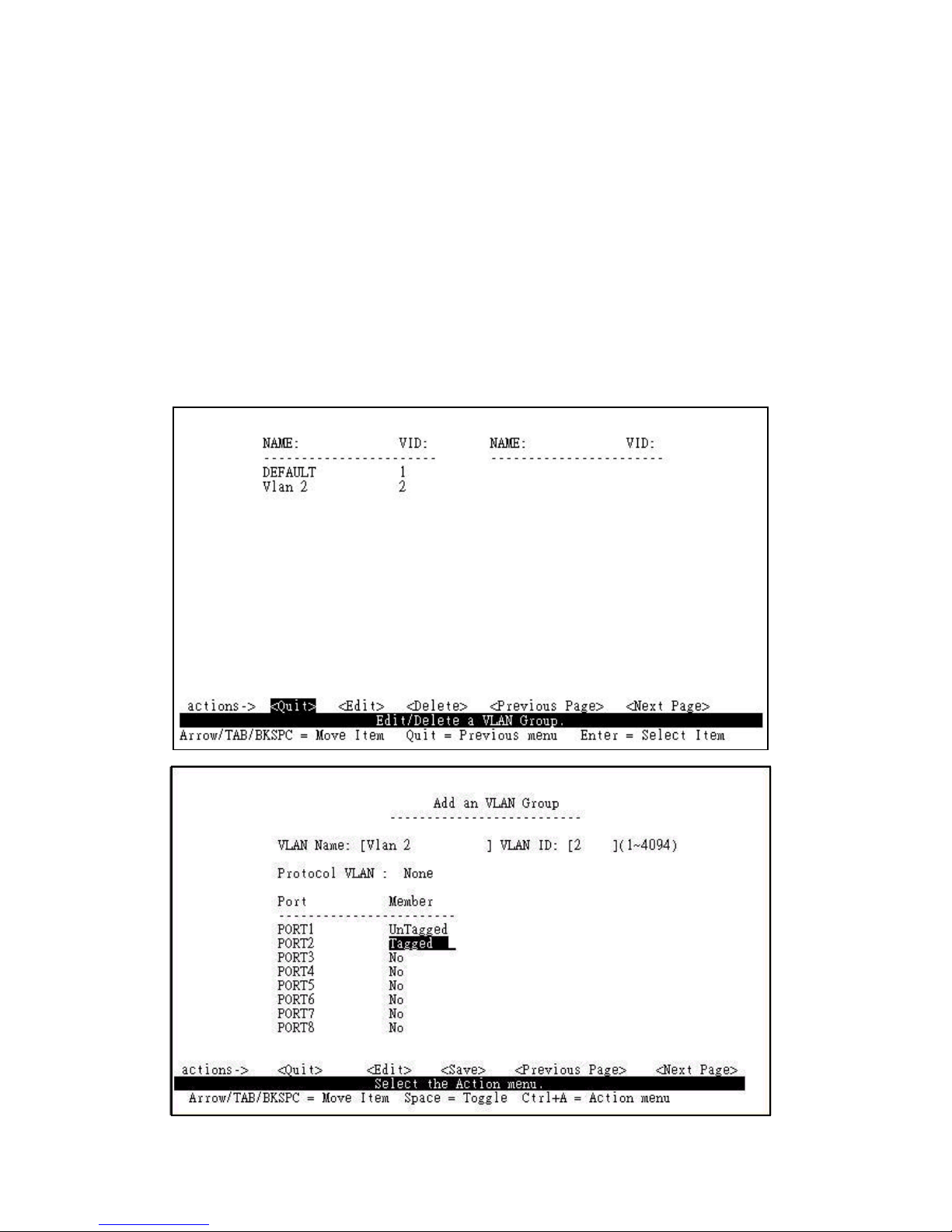
6.2.3.2 Edit / Delete a VLAN Group
In this page, you can edit or delete a VLAN group.
1.Press <Edit> or <Delete> item.
2.Choose the VLAN group that you want to edit or delete and then press enter.
3.You can modify the protocol VLAN item and the member port as tagged or un-tagged and remove
some member ports from this VLAN group.
4.After edit VLAN, press <Save> key to save all configures value.
NOTE:
1. Press <Enter> once will complete deletion on delete mode.
2. The VLAN Name and VLAN ID cannot be modified.
3. The default VLAN cant be deleted.
#"
Page 60
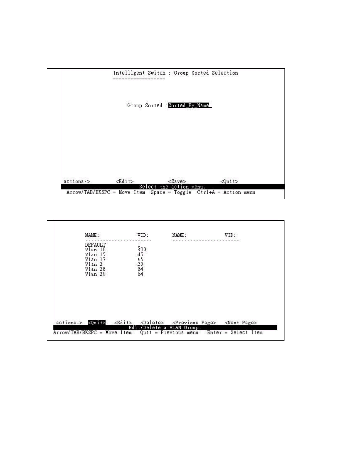
6.2.3.3 Groups Sorted Mode
In this page, you can select VLAN groups sorted mode as (1) sorted by name (2) sorted by VID.
In the Edit/Delete a VLAN group page will display the result.
In the Edit/Delete a VLAN Group page, the result of sorted by name.
In the Edit/Delete a VLAN Group page, the result of sorted by VID.
##
Page 61
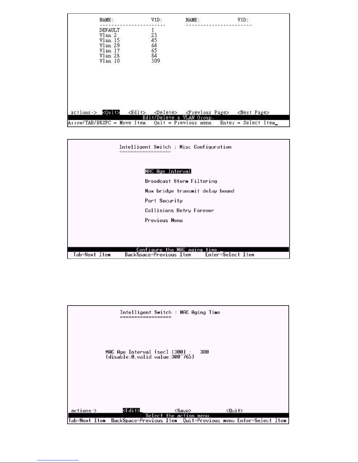
6.2.4 Misc Configuration
6.2.4.1 MAC Age Interval
Type the number of seconds that an inactive MAC address remains in the switchs address table. The
valid range is 300~765 seconds. Default is 300 seconds.
#$
Page 62
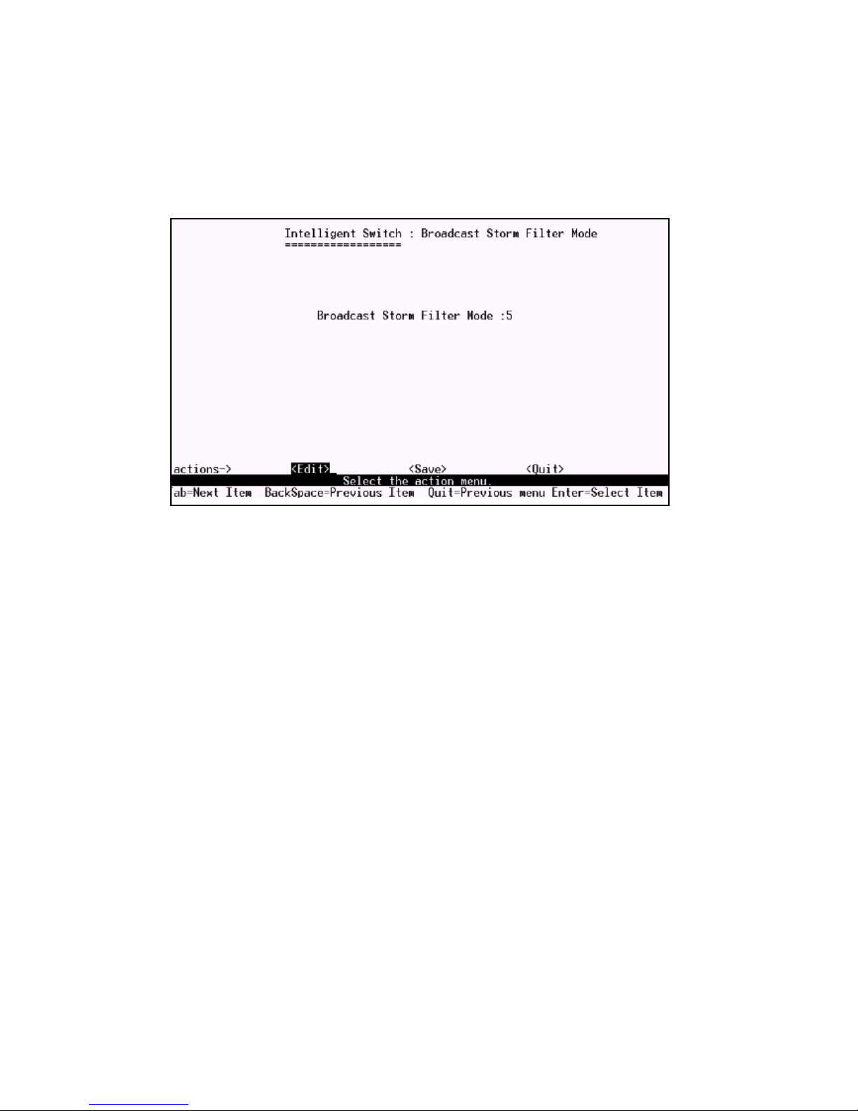
6.2.4.2 Broadcast Storm Filtering
In this page you can configure broadcast storm settings.
1.Press <Edit> to configure the broadcast storm filter mode.
2.Press Space key to choose the threshold value.
The valid threshold value are 5%,10%,15%,20%,25% and NO.
#%
Page 63

6.2.4.3 Max bridge transmit delay bound
1.Max bridge transmit delay bound: Limit the packets queuing time in switch. If enable, the packets
queued exceed will be drop. Press Space key to set the time. This valid value are 1sec, 2sec, 4sec and
off. Default is off.
2.Low Queue Delay Bound: Limit the low priority packets queuing time in switch. If enable, the low
priority packet stays in switch exceed Low Queue Max Delay Time, it will be sent.
Press Space key to enable or disable this function.
3.Low Queue Max Delay Time: To set the time that low priority packets queuing in switch. Default
Max Delay Time is 255ms. The valid range is 1~255 ms.
NOTE: Make sure of Max bridge transit delay bound control is enabled before enable Low Queue
Delay Bound, because Low Queue Delay Bound must be work under Max bridge transit delay bound
control is enabled situation.
#&
Page 64
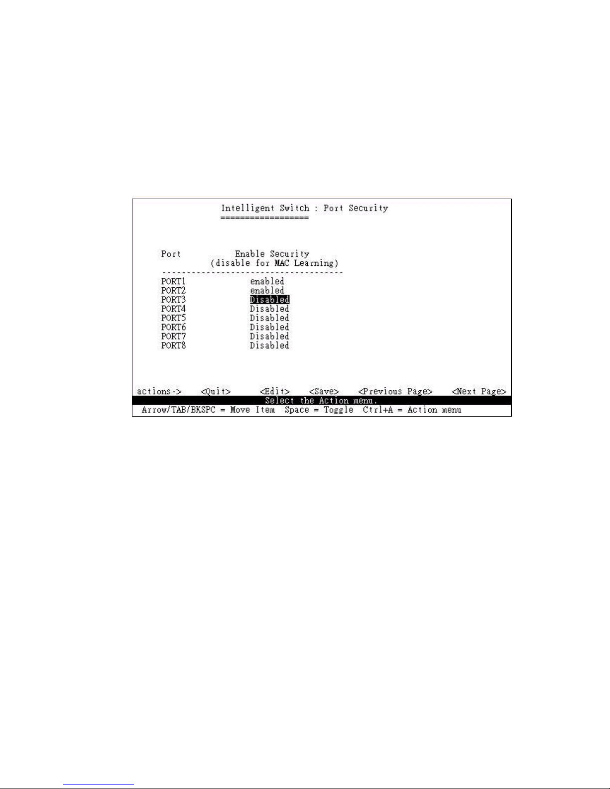
6.2.4.4 Port Security
A port in security mode will be locked without permission of address learning. Only the incoming
packets with SMAC already existing in the address table can be forwarded normally. You can disable
the port from learning any new MAC addresses, then use the static MAC addresses screen to define a
list of MAC addresses that can use the secure port.
1.Select <Edit>.
2.Press Space key to choose enable / disable item.
3.Press Ctrl+A to go back action menu line.
4.Select <Save> to save all configure value.
5.You can press <Next Page> to configure port9 ~ port26 and press <Previous Page> to return to
last page.
#'
Page 65
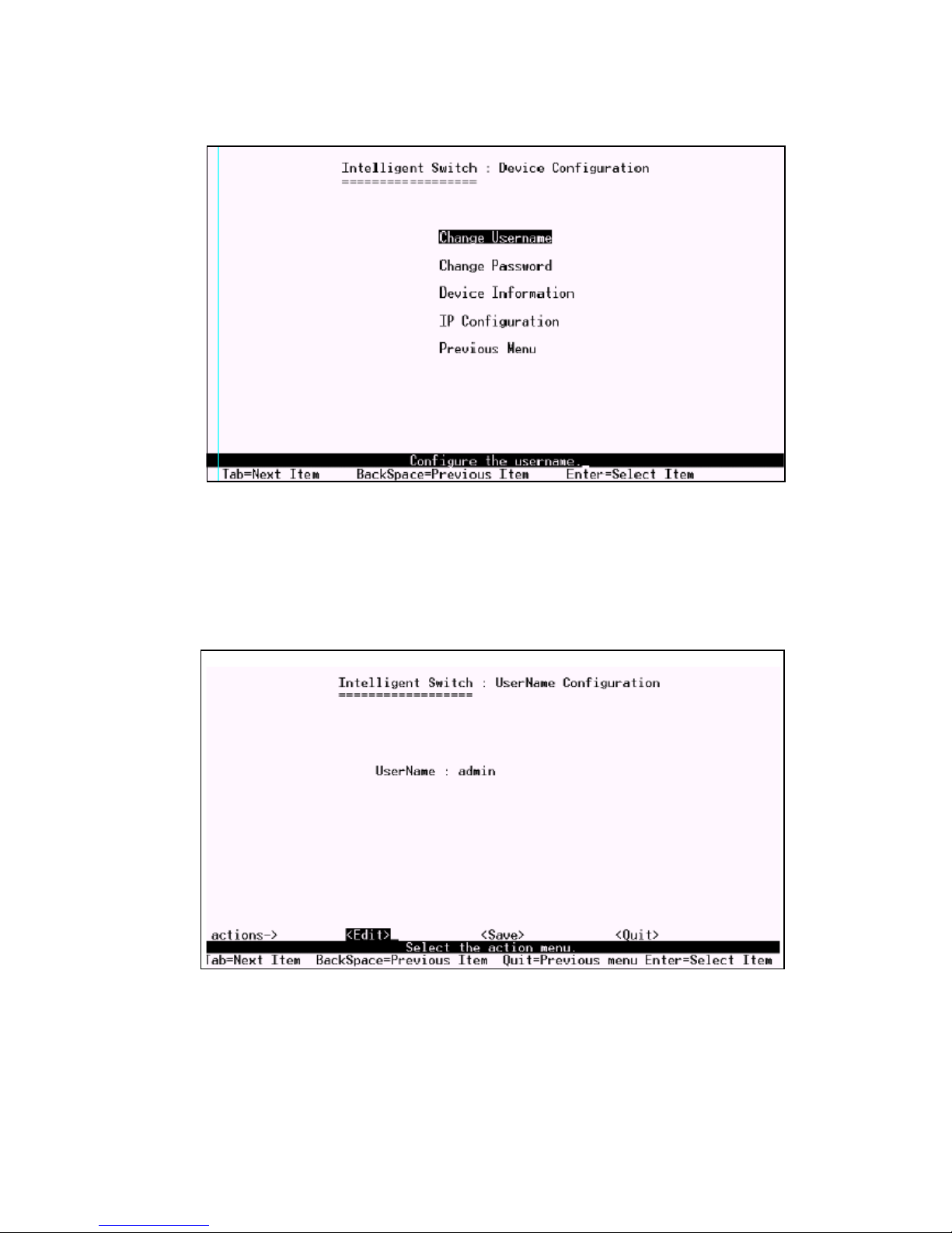
6.2.5 Administration Configuration
6.2.5.1 Change Username
You can change web management user name in this page. Type the new user name, then
press <Save> item.
$
Page 66
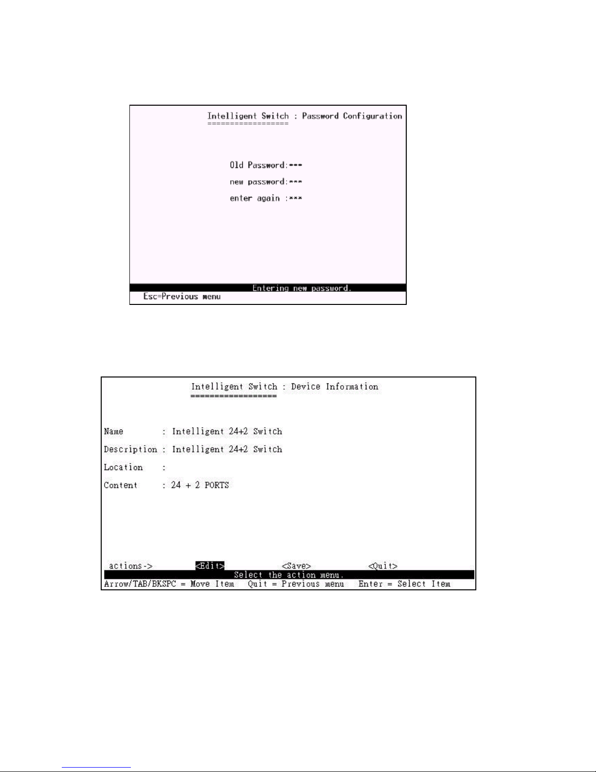
6.2.5.2 Change Password
In this page you can change web management login password.
6.2.5.3 Device Information
This page provide user to configure the device information.
$
Page 67
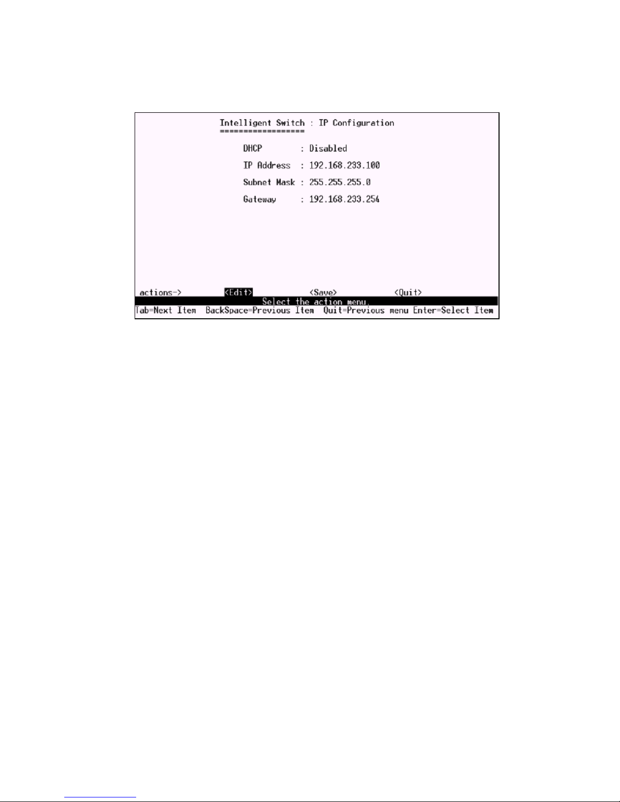
6.2.5.4 IP Configuration
You can configure the IP setting and fill in the new value.
$
Page 68
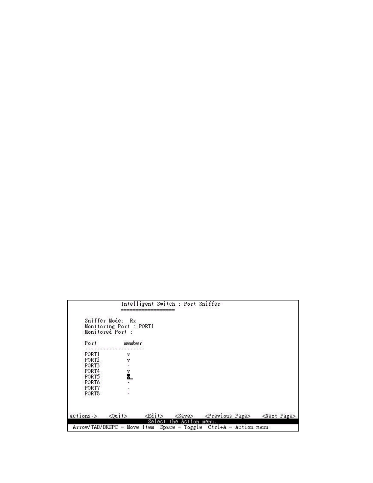
6.2.6 Port Mirroring Configuration
The port mirroring is a method for monitor traffic in switched networks. Traffic through ports can be
monitored by one specific port. That is, traffic goes in or out monitored ports will be duplicated into
monitoring port.
Press Space key to change configure of each item.
1.Select <Edit>.
2.Sniffer Mode: Press Space key to set sniffer mode: Disable\Rx\Tx\Both.
3.Monitoring Port: It means sniffer port can be used to see all monitor port traffic. Press Space key
to choose it.
4.Monitored Port: The ports you want to monitor. All monitor port traffic will be copied to sinffer
port. You can select max 25 monitor ports in the switch. You can choose which port want to be monitored in only one sniffer mode.
Press Space key to choose member port,V is the member, not the member.
5.Press Ctrl+A go back action menu line
6.Select <Save> to save all configure value.
7.On the action menu line you can press <Next Page> to configure port9 ~ port26, press <Previous
Page> return to last page.
NOTE: Only have one sniffer mode in this switch at the same time.
$!
Page 69
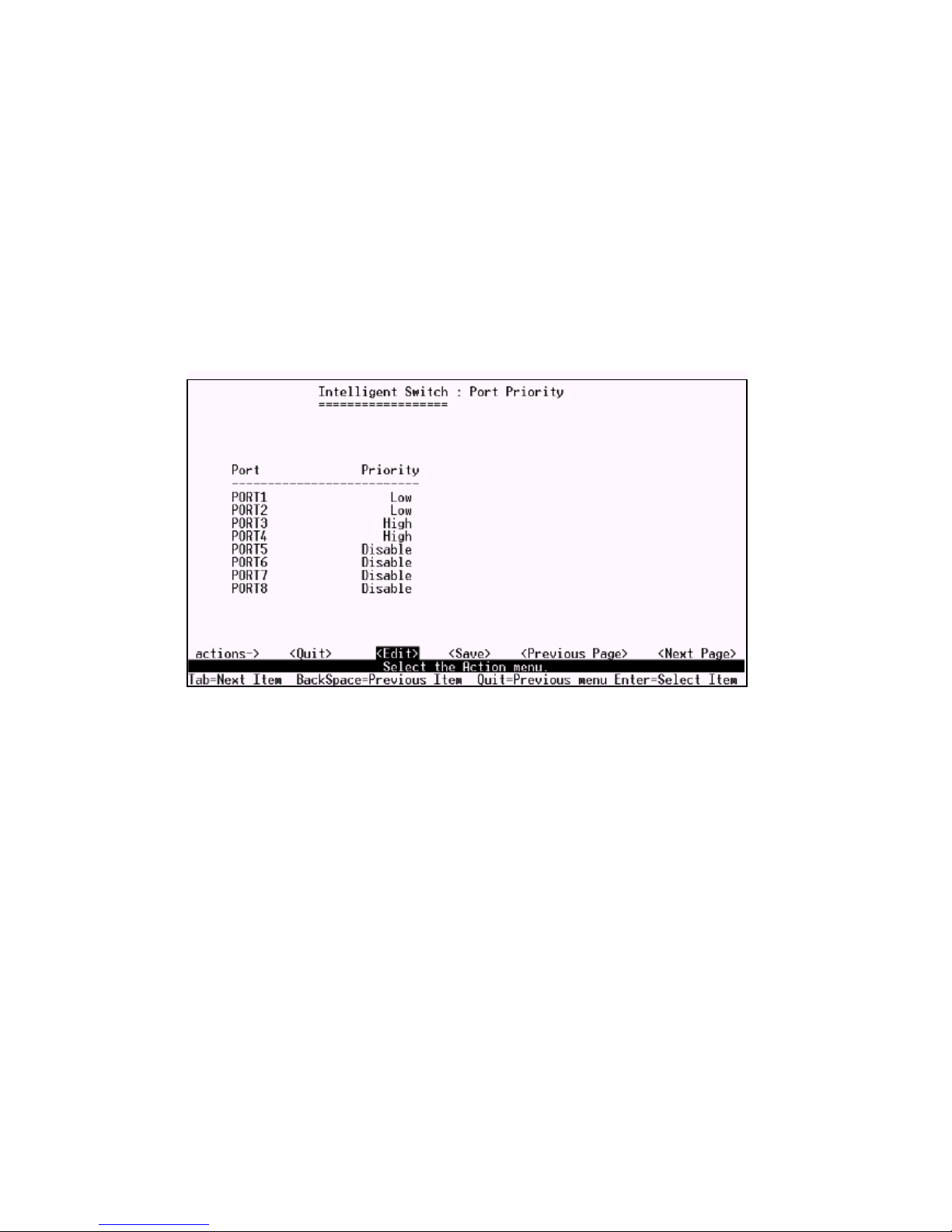
6.2.7 Priority Configuration
There are 0~7 priority levels can map to high or low queue.
1.Select <Edit>.
2.Press Space key to select the priority level mapping to high or low queue.
3.High/Low Queue Service Ration H:L : You can select the ratio of high priority packets and low
priority packets.
4.Press Ctrl+A go back action menu line.
5.Selcet <Save> to save all configure value.
$"
Page 70
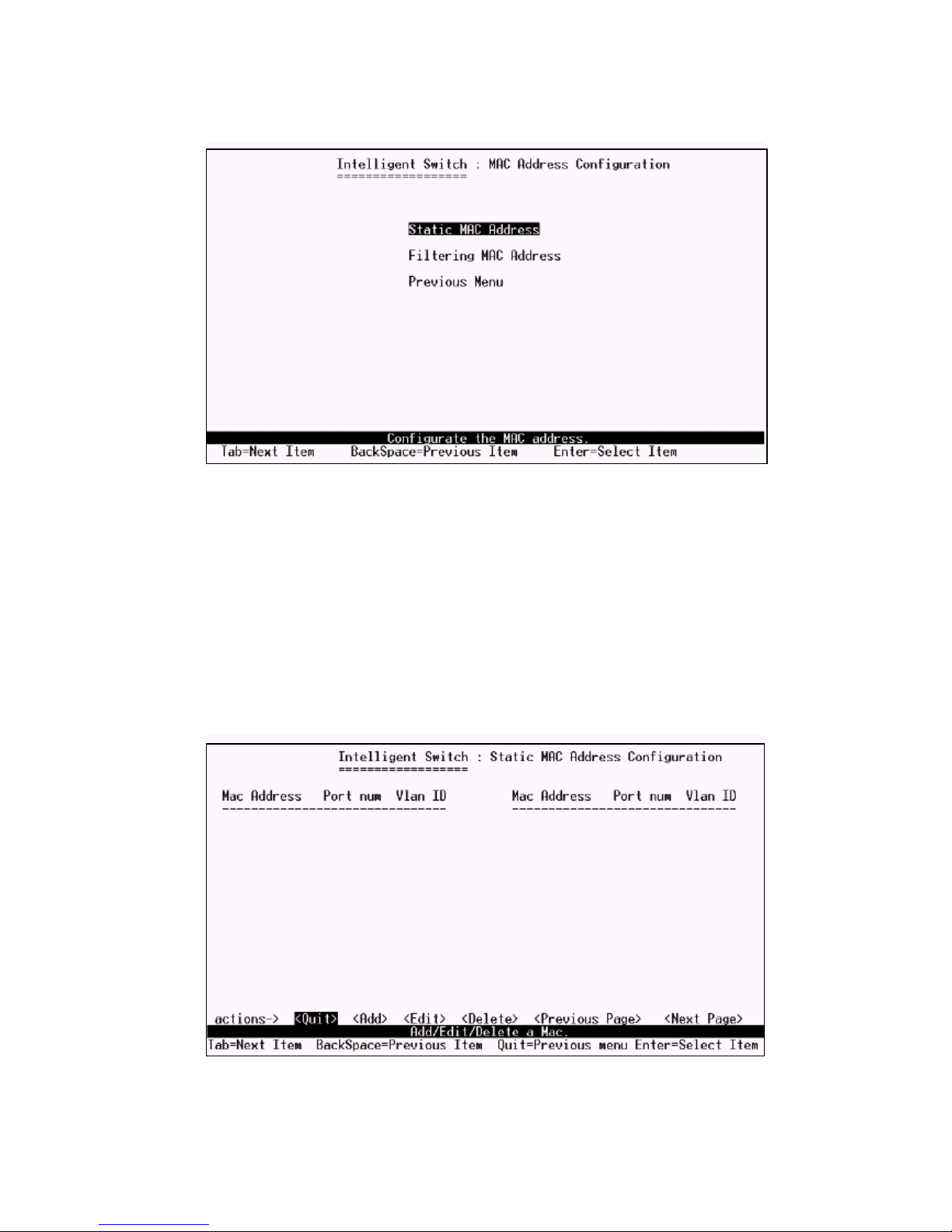
6.2.8 MAC Address Configuration
6.2.8.1 Static MAC Address
When you add a static MAC address, it remains in the switchs address table, regardless of whether
the device is physically connected to the switch. This saves the switch from having to re-learn a devices
MAC address when the disconnected or powered-off device is active on the network again.
In this page you can add/modify/delete a static MAC address.
$#
Page 71
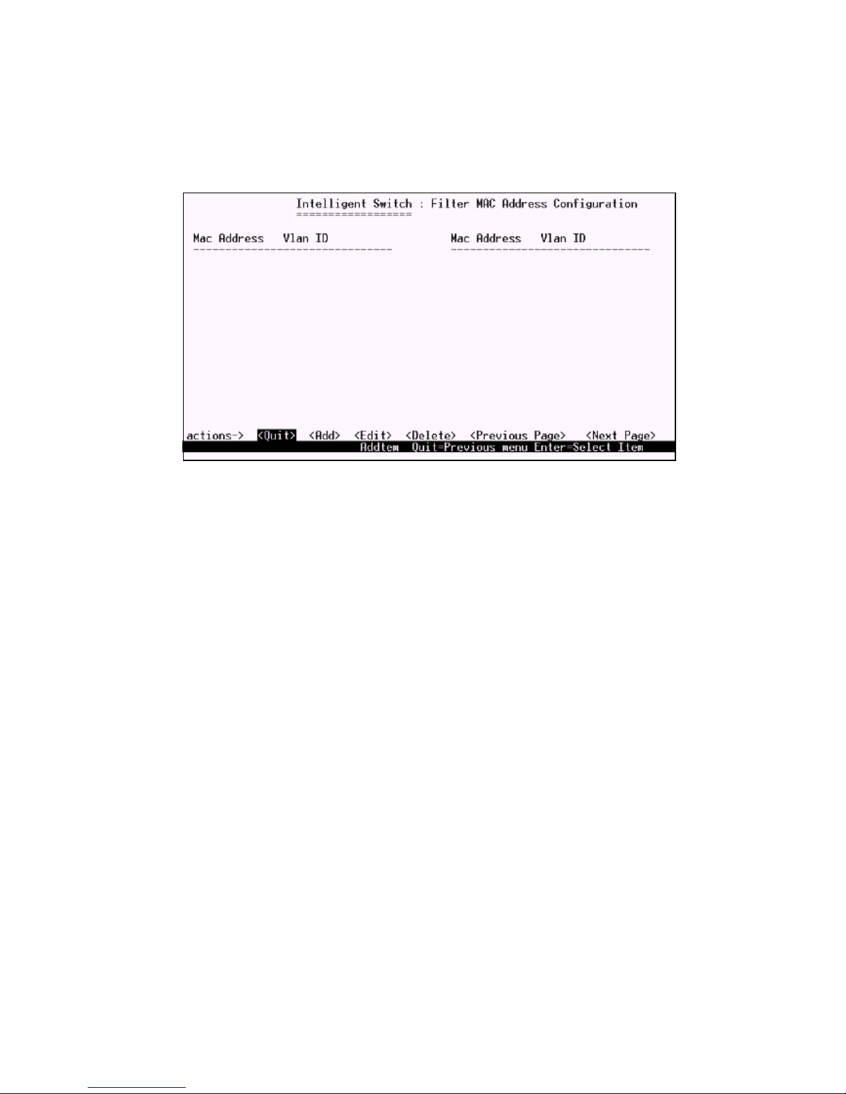
6.2.8.2 Filtering MAC Address
MAC address filtering allows the switch to drop unwanted traffic. Traffic is filtered based on the
destination addresses. In this page you can add/modify/delete the filtering MAC address.
$$
Page 72
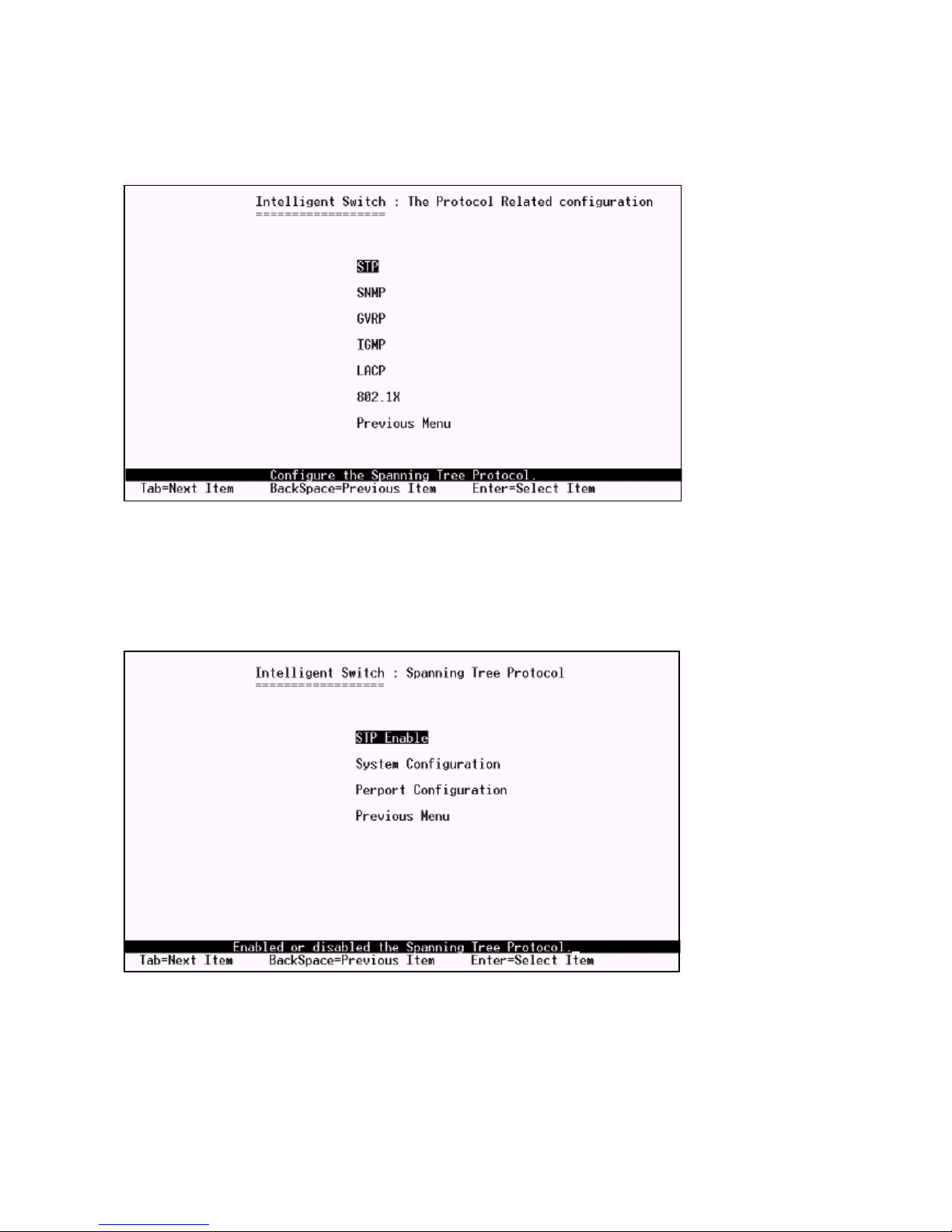
7. Protocol Related Configuration
7.1 STP
$%
Page 73
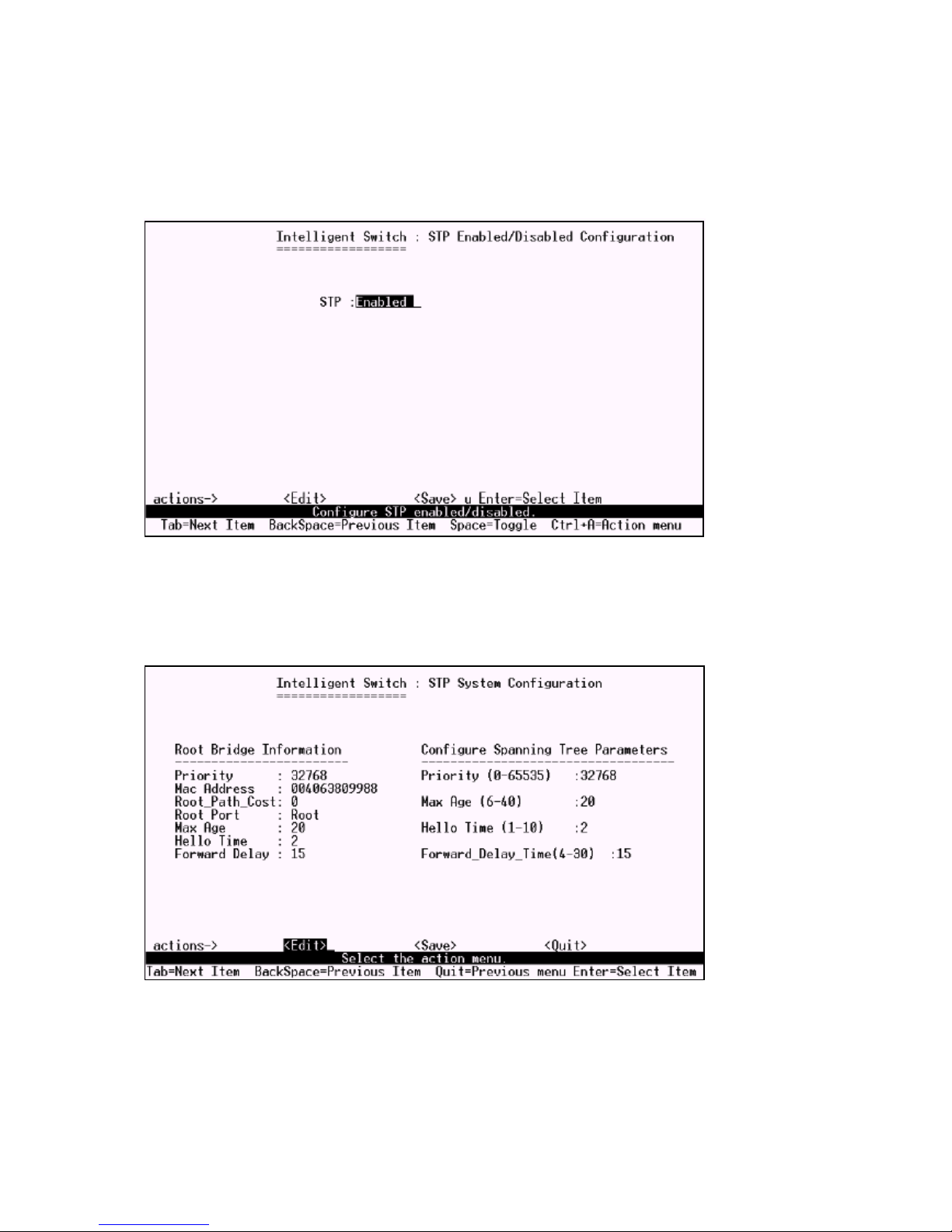
7.1.1 STP Enable
You can enable or disable Spanning Tree function in this page. Press Space key to select enable or
disable.
7.1.2 System Configuration
1.You can view spanning tree information about the Root Bridge on the left.
2.On the right, you can set new values for STP parameters.
$&
Page 74
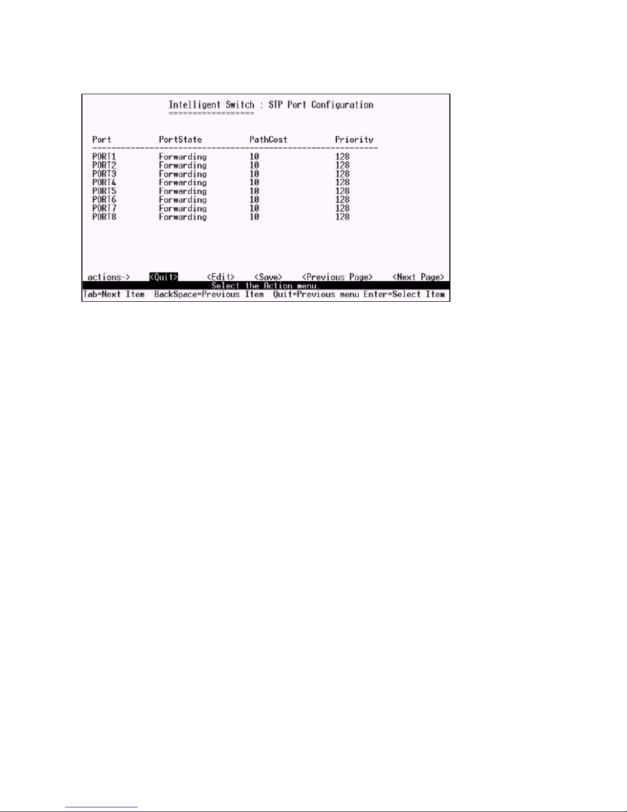
7.1.3 Perport Configuration
1.PortState: Display spanning tree status about the switch for per port as forwarding or blocking.
2.Select <Edit>.
3.PathCost: Specifies the path cost of the port that switch uses to determine which port are the forwarding ports.
4.Priority: This means port priority. You can make it more or less likely to become the root port.
5.Press Ctrl+A go back action menu line.
6.Select <Save> to save all configure value.
7.On the action menu line you can press <Next Page> to configure port9 ~ port26, press <Previous
Page> to return to last page.
$'
Page 75
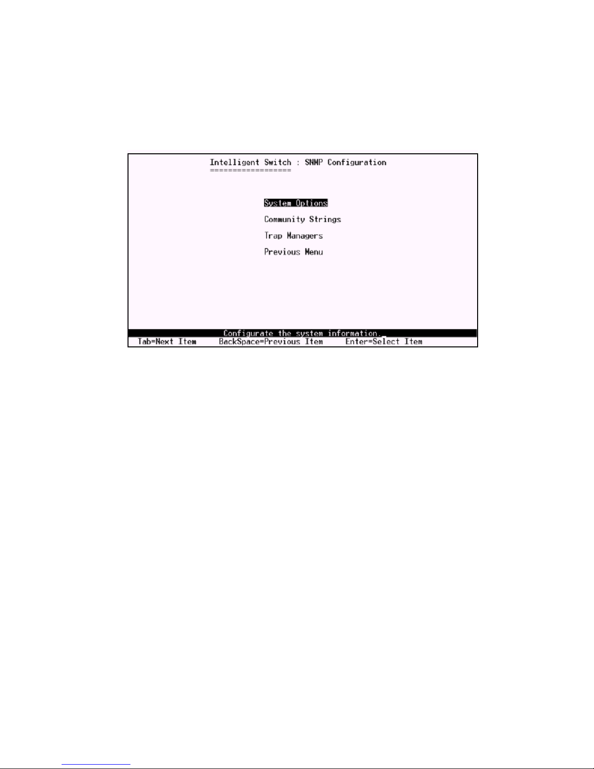
7.2 SNMP
Use this page to define management stations as trap managers and to enter SNMP community strings.
You can also define a name, location, and contact person for the switch.
%
Page 76
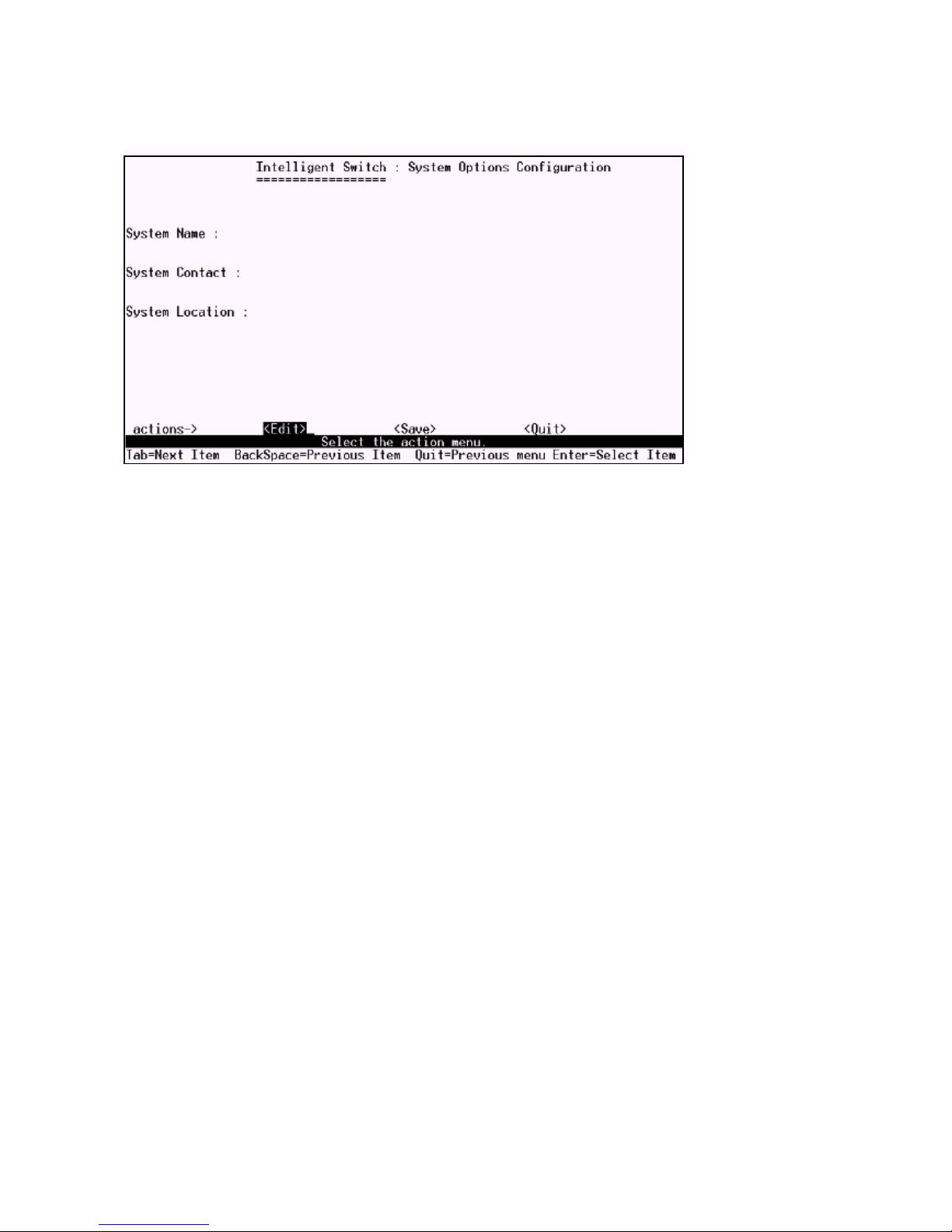
7.2.1 System Options
1.Press <Edit>.
2.System Name: Type a name to be used for the switch.
3.System Contact: Type the name of contact person or organization.
4.System Location: Type the location of the switch.
5.Press Ctrl+A go back action menu line.
6. Press <Save> to save configure value.
%
Page 77
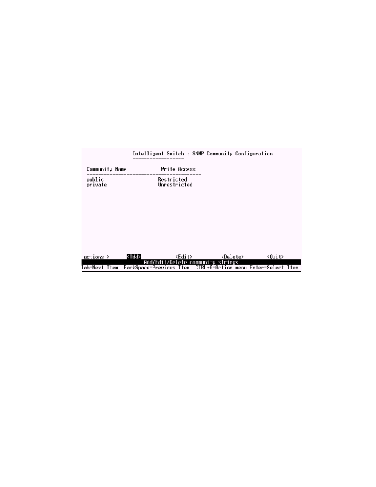
7.2.2 Community Strings
Use this page to add/edit/delete SNMP community strings.
1.Community Name: The name of current strings.
2.Write Access: Enable the rights is read only or read write.
Restricted: Read only, enables requests accompanied by this string to display MIB-object information.
Unrestricted: Read write, enables requests accompanied by this string to display MIB-object informa-
tion and to set MIB objects.
%
Page 78
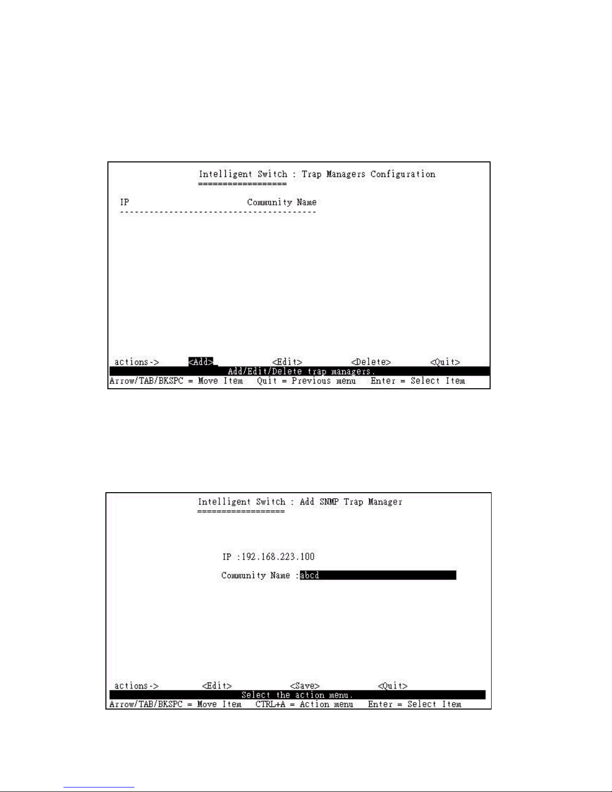
7.2.3 Trap Managers
A trap manager is a management station that receives traps, the system alerts generated by the switch.
If no trap manager is defined, no traps are issued. Create a trap manager by entering the IP address of
the station and a community string.
Add the trap manager
1.Press <Add> -> <Edit> to add the trap manager.
2.IP: Type the IP address.
3.Community Name: Type the community name.
4.Press Ctrl+A go to actions line, then press <Save> key to save all configure.
%!
Page 79
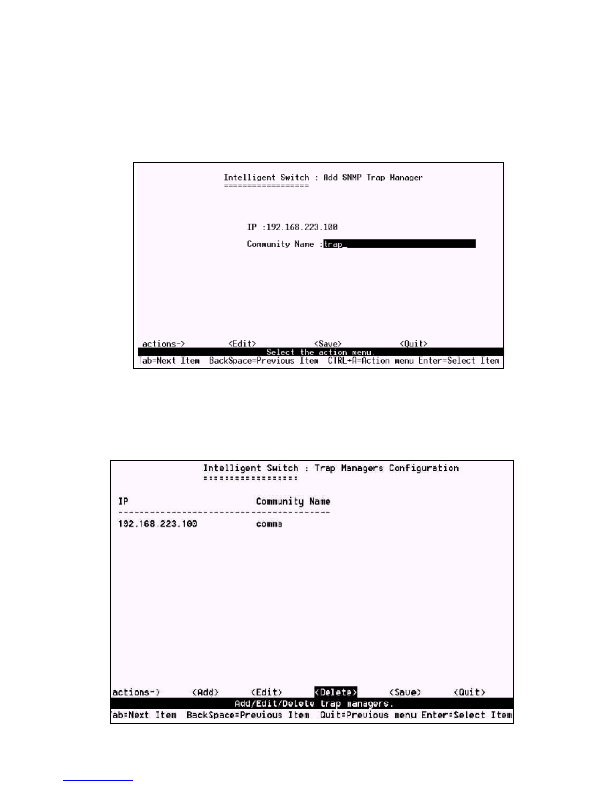
Edit trap manager
1.Press <Edit> key to choose the item that you want to modify.
2.Press <Edit> key.
3.IP: Type the new IP address.
4.Community Name: Type the community name.
5.Press Ctrl+A go to actions line, press <Save> key to save all configure.
Delete trap manager
1.Press <Delete> key.
2.Choose the trap manager that you want to delete and then press enter.
3. Press <Enter> once will complete deletion on delete mode.
%"
Page 80
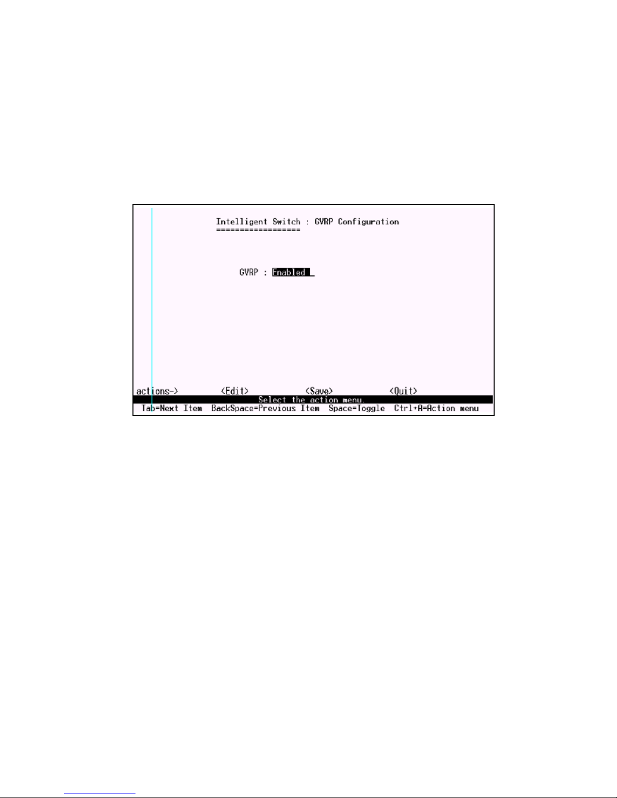
7.3 GVRP
In this page you can enable/disable the GVRP (GARP VLAN Registration Protocol) support.
1.Select <Edit>.
2.Press Space key to choose Enabled / Disabled.
3.Press Ctrl+A go back action menu line.
4.Select <Save> to save configure value.
%#
Page 81
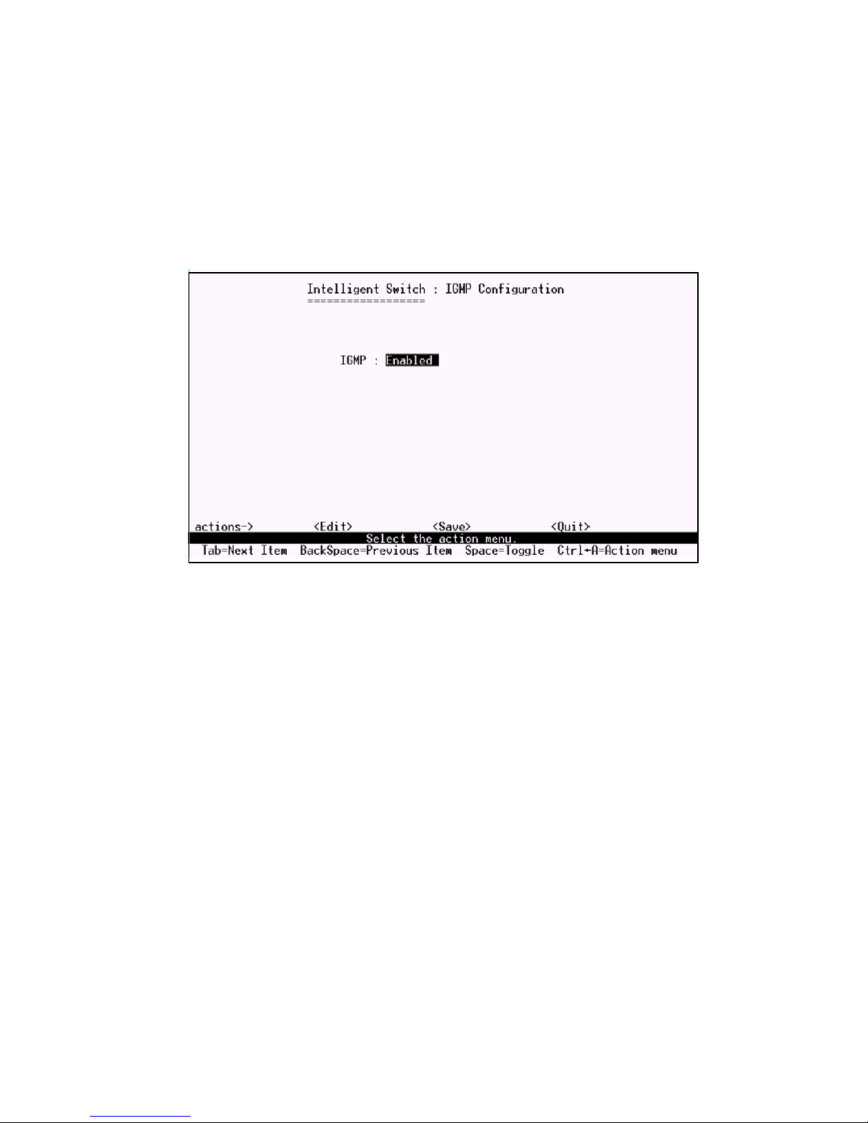
7.4 IGMP
In this page you can enable / disable the IGMP support.
1.Select <Edit>.
2.Press Space key to choose Enabled / Disabled.
3.Press Ctrl+A go back action menu line.
4.Select <Save> to save configure value.
%$
Page 82
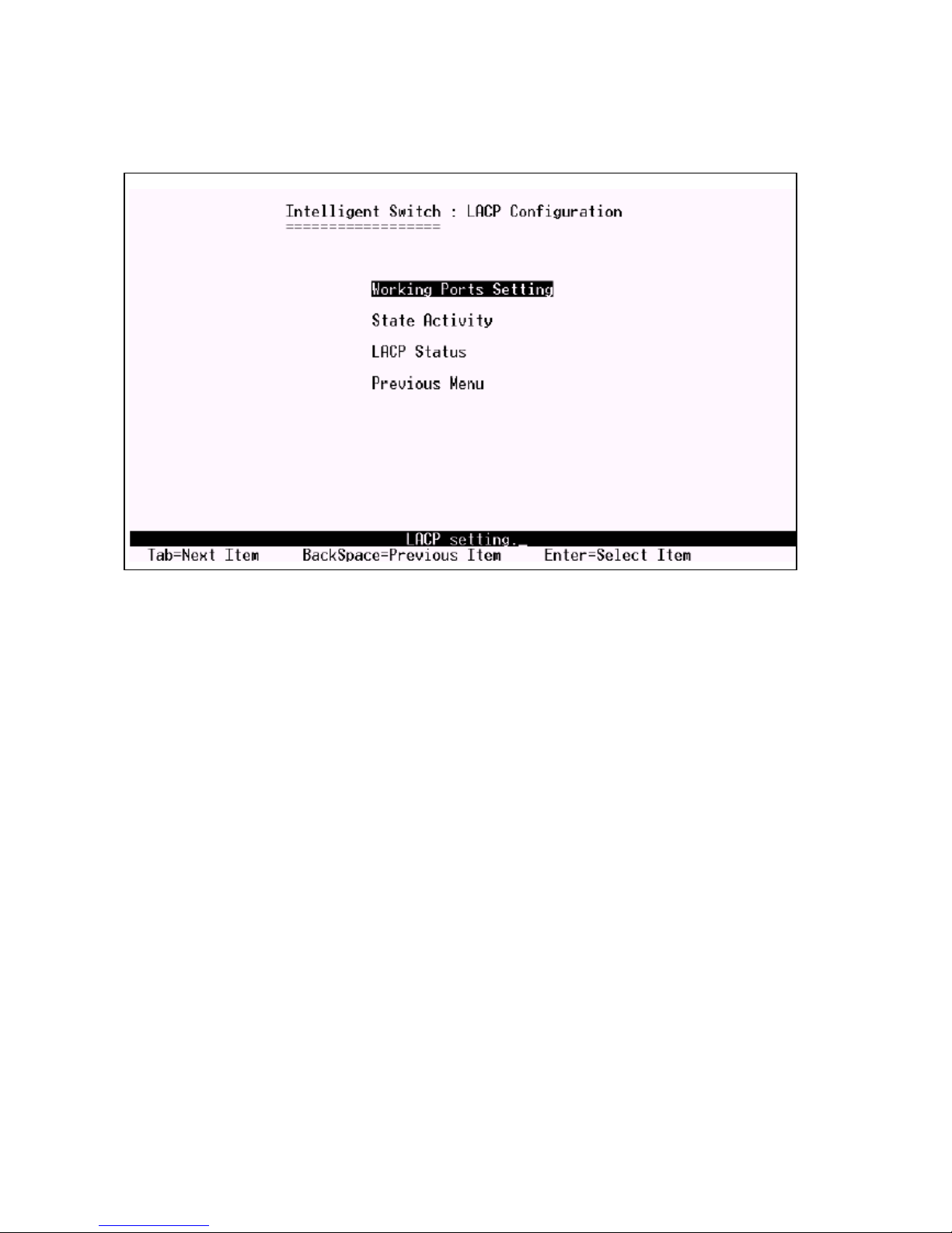
7.5 LACP
In this page you can configure and view all the LACP status.
%%
Page 83
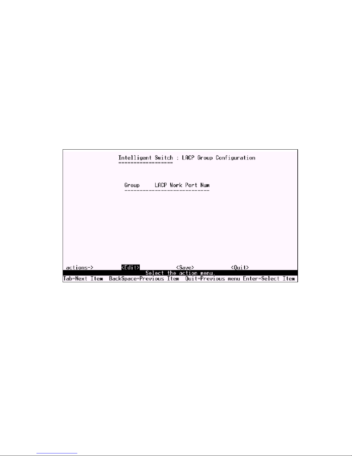
7.5.1 Working Port Setting
This page can set the actually work ports in trunk group.
1.Select <Edit>.
2.Group: Display the trunk group ID.
3.LACP: Display the trunk groups LACP status.
4.LACP Work Port Num: The max number of ports can be aggregated at the same time. If LACP
static trunking group, the exceed ports is standby and able to aggregate if work ports fail.
NOTE: Before set this page, you have to set trunk group on the page of Trunk Configuration first.
%&
Page 84
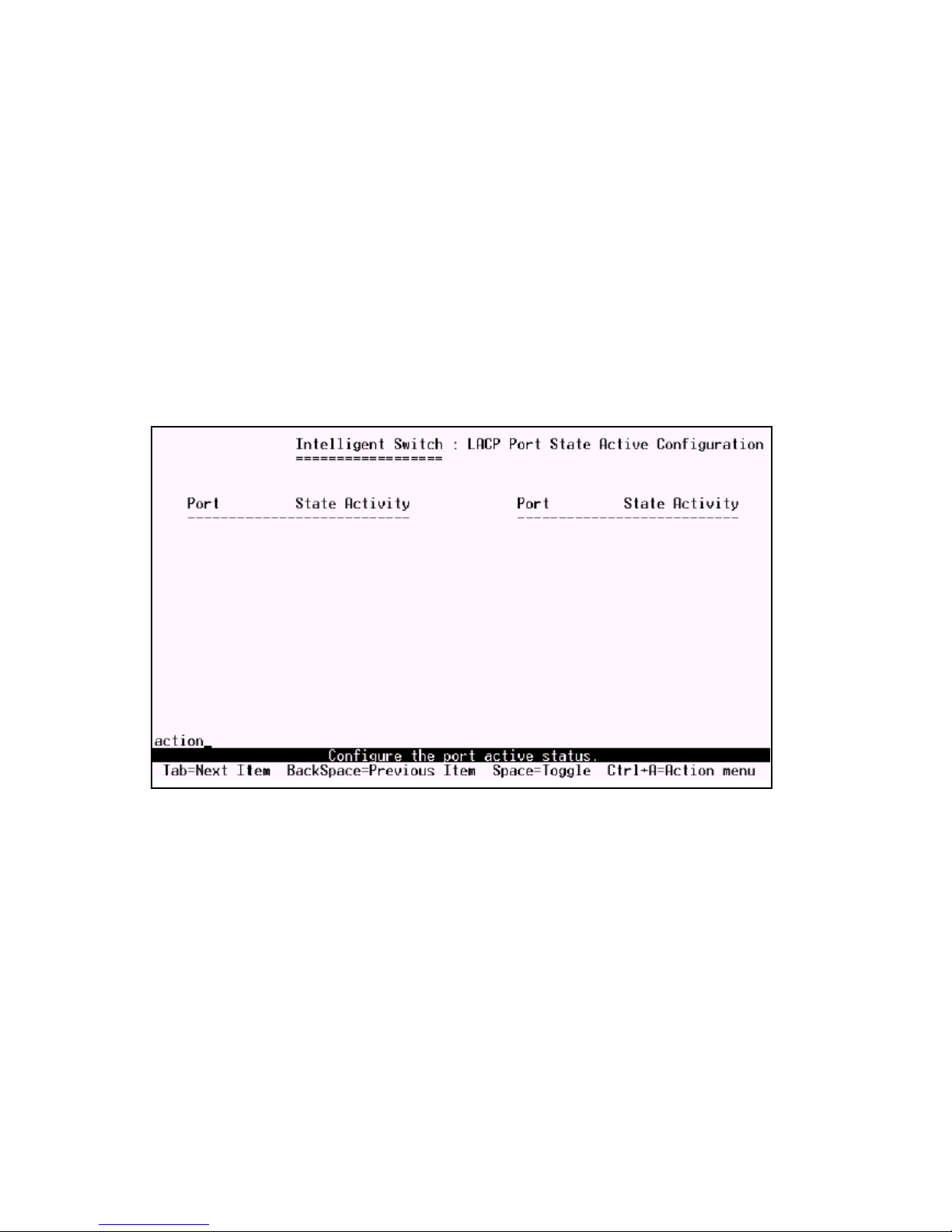
7.5.2 State Activity
1.Select <Edit>.
2.Press Space key to choose the item.
Active: The port automatically sends LACP protocol packets.
Passive: The port does not automatically send LACP protocol packets, and responds only if it re-
ceives LACP protocol packets from the opposite device.
3.Press Ctrl+A go back action menu line.
4.Select <Save> to save configure value.
If user set LACP mode in the trunk group, all of the member ports of this trunk group will set Active
automatic.
%'
Page 85
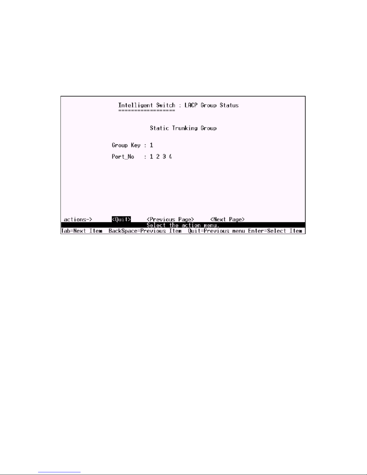
7.5.3 LACP Status
When you set trunking groups you can see relation information here.
<Quit>: Exit this page and return to previous menu.
<Previous Page>: Return to previous page to view.
<Next page>: Go to next page to view.
&
Page 86
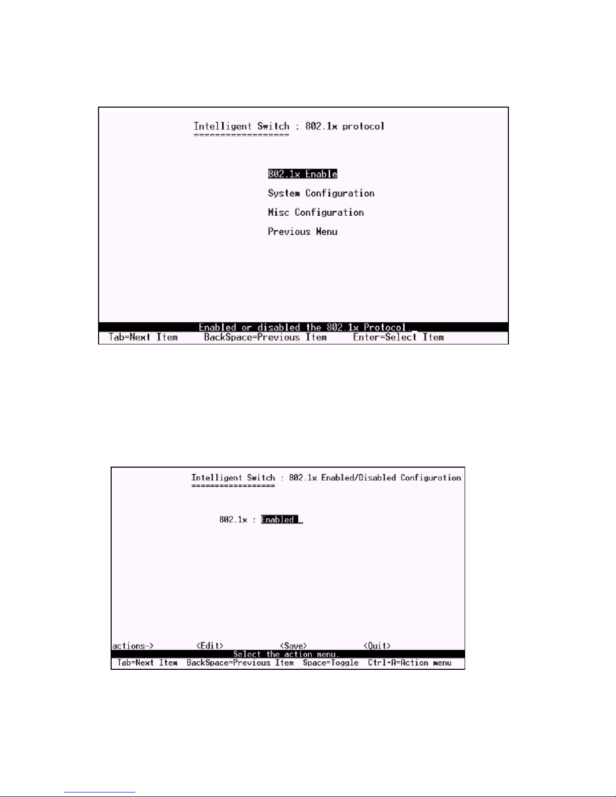
7.6 802.1X Configuration
7.6.1 Enable 802.1X function
Press Space key to enable or disable the 802.1x function.
&
Page 87
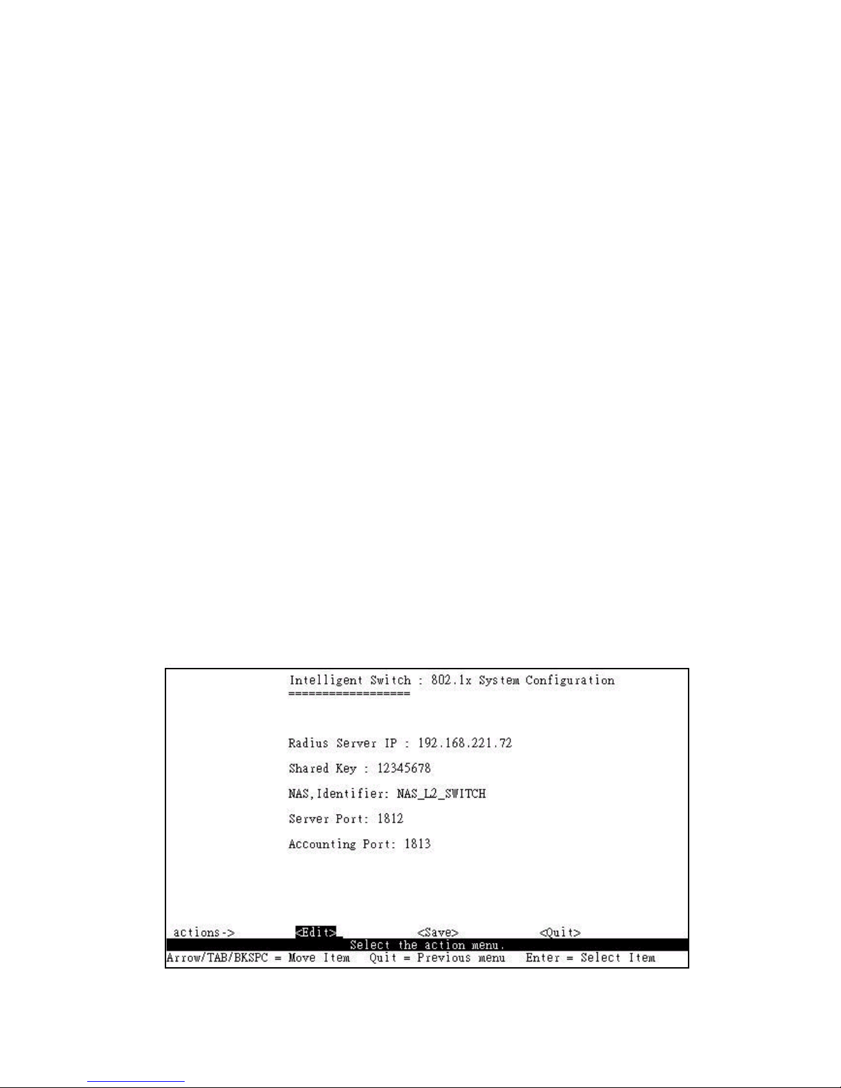
7.6.2 System Configuration
If you enable the IEEE 802.1X function, you can configure the parameters of this function.
1. Radius Server IP: Set the Radius Server IP address
2. Shared Key: Set an encryption key for use during authentication sessions with the specified radius
server. This key must match the encryption key used on the Radius
Server.
3. NAS, Identifier: Set the identifier for the radius client.
4. Server Port: Set the UDP destination port for authentication requests to the specified Radius Server.
5. Accounting Port: Set the UDP destination port for accounting requests to the specified Radius
Server.
There are four types for each port:
Fu, Force unauthorized: The specified port is required to be held in the Unauthorized state.
Fa, Force authorized: The specified port is required to be held in the Authorized state.
Au, Auto: The specified port is set to the Authorized or Unauthorized state in accordance with the
outcome of an authentication exchange between the Supplicant and the authentication server.
No, None: The specified port is required to be held in the Authorized state.
&
Page 88
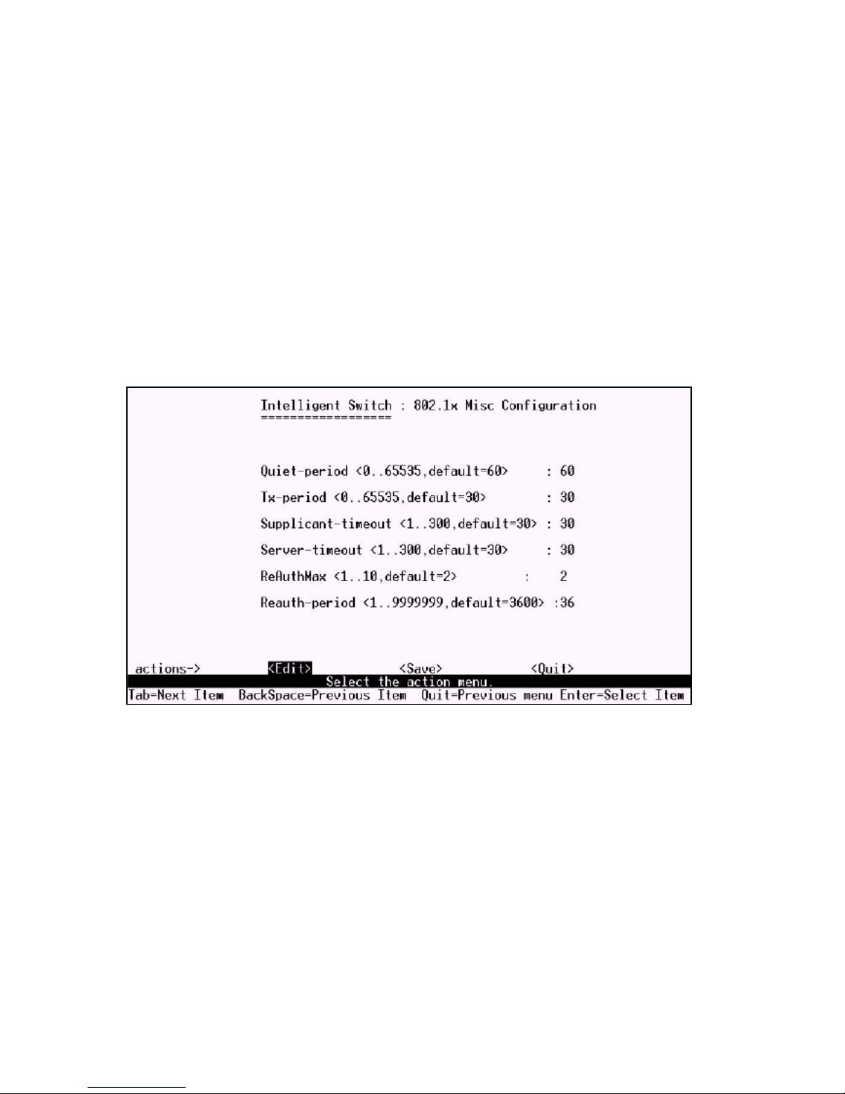
7.6.3 Misc Configuration
1. Quiet period: Set the period during which the port doesnt try to acquire a supplicant.
2. Tx period: Set the period the port waits to retransmit next EAPOL PDU during an authentication
session.
3. Supplicant timeout: Set the period of time the switch waits for a supplicant response to an EAP
request.
4. Server timeout: Set the period of time the switch waits for a server response to an authentication
request.
5. Max requests: Set the number of authentication attemps that must time-out before authentication fails
and the authentication session ends.
6. Reauth period: Set the period of time after which clients connected must be re-authenticated
&!
Page 89
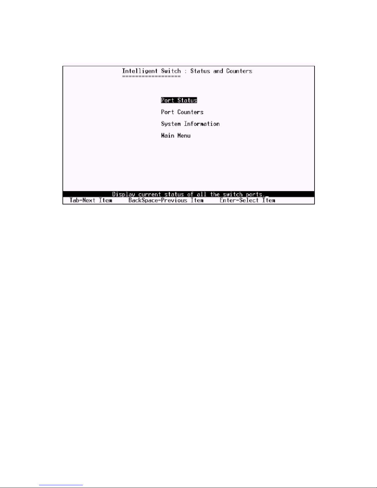
8. Status and Counters
You can press the key of Tab or Backspace to choose each item, and press Enter key to select the
item.
&"
Page 90
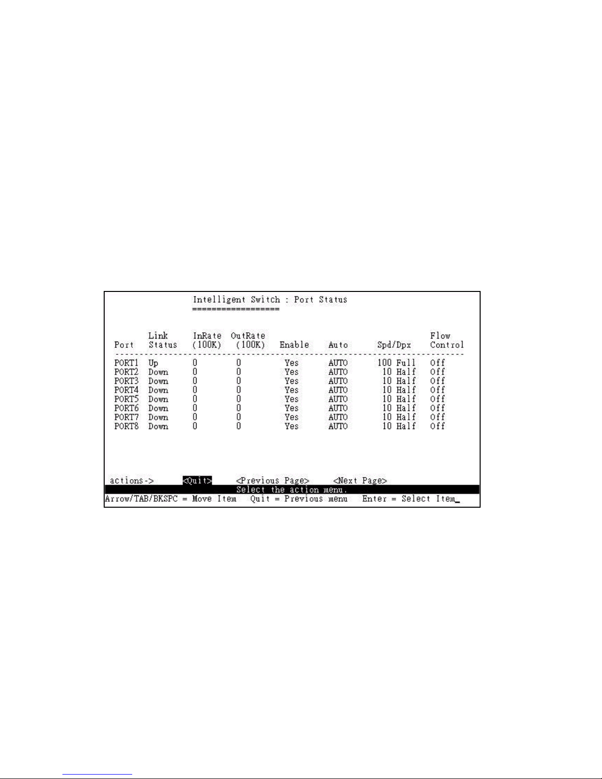
8.1 Port Status
This page displays the status of each port.
Link Status: Down and Up means No Link and Link respectively.
InRate: Displays the input rate control (100K/unit) setting values.
OutRate: Displays the output rate control (100K/unit) setting values.
Enabled: Displays the port is enabled or disable depended on user settings. Enable will be displayed as
Yes, disable will be displayed as No. If the port is unlink it will be treated as No.
Auto: Displays the port is link on which Nway mode: Auto ,Nway_Force , Force.
Spd/Dpx: Displays the port speed and duplex.
Flow Control: In auto / Nway force mode, displays the flow control status is enable or disable after
negotiation.In force mode, displays the flow control status is enable or disable depending on user
settings.
&#
Page 91
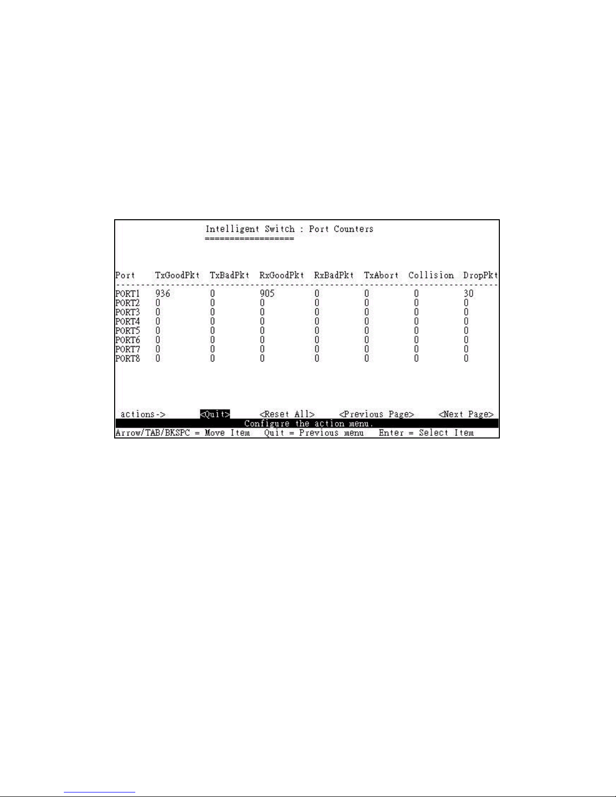
8.2 Port Counters
The following information provides a view of the current status of the unit.
<Quit>: Exit the page of port status, and return to previous menu.
<Reset All>: Set all count to 0.
<Previous Page>: Display previous page.
<Next page>: Display next page.
&$
Page 92
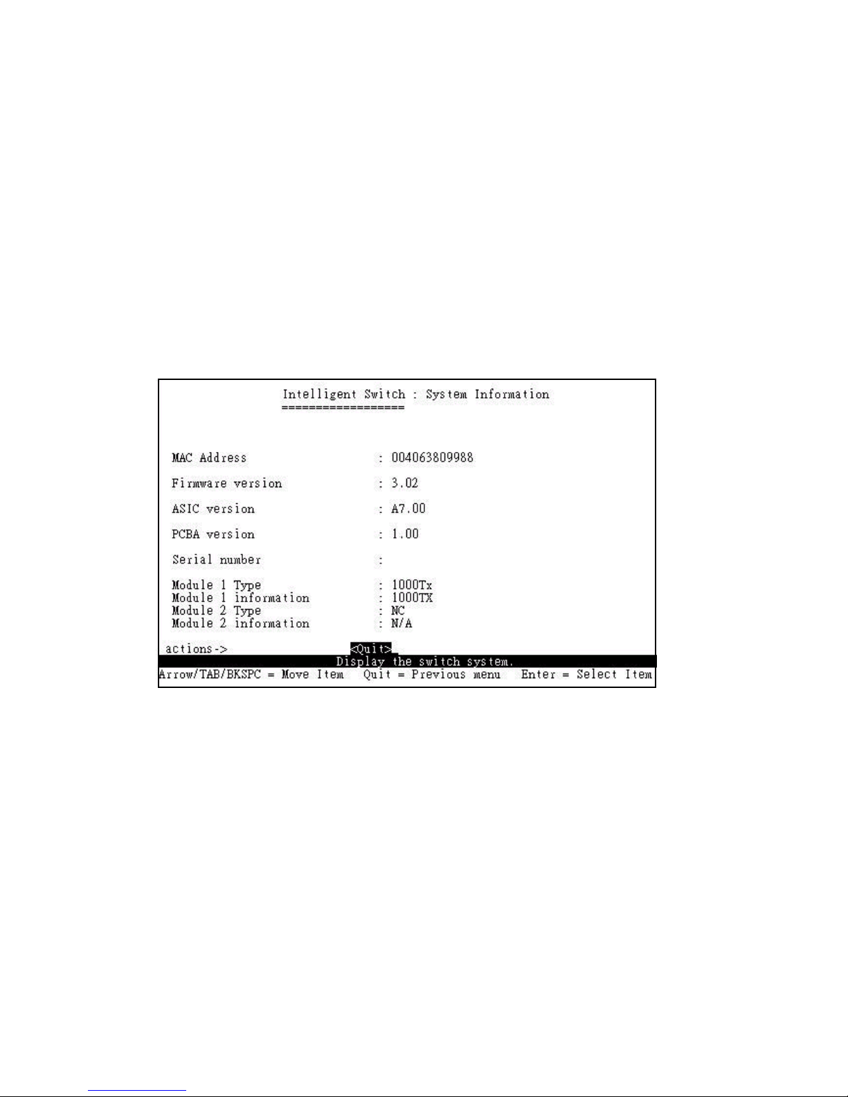
8.3 System Information
MAC Address: The unique hardware address assigned by manufacturer.
Firmware Version: Display the switchs firmware version.
Hardware Version: Display the switchs Hardware version.
Default config value version: Display write to default eeprom value tale version.
Module1 information: Display the information saved in eeprom of module1.
Module2 information: Display the information saved in eeprom of module2.
&%
Page 93
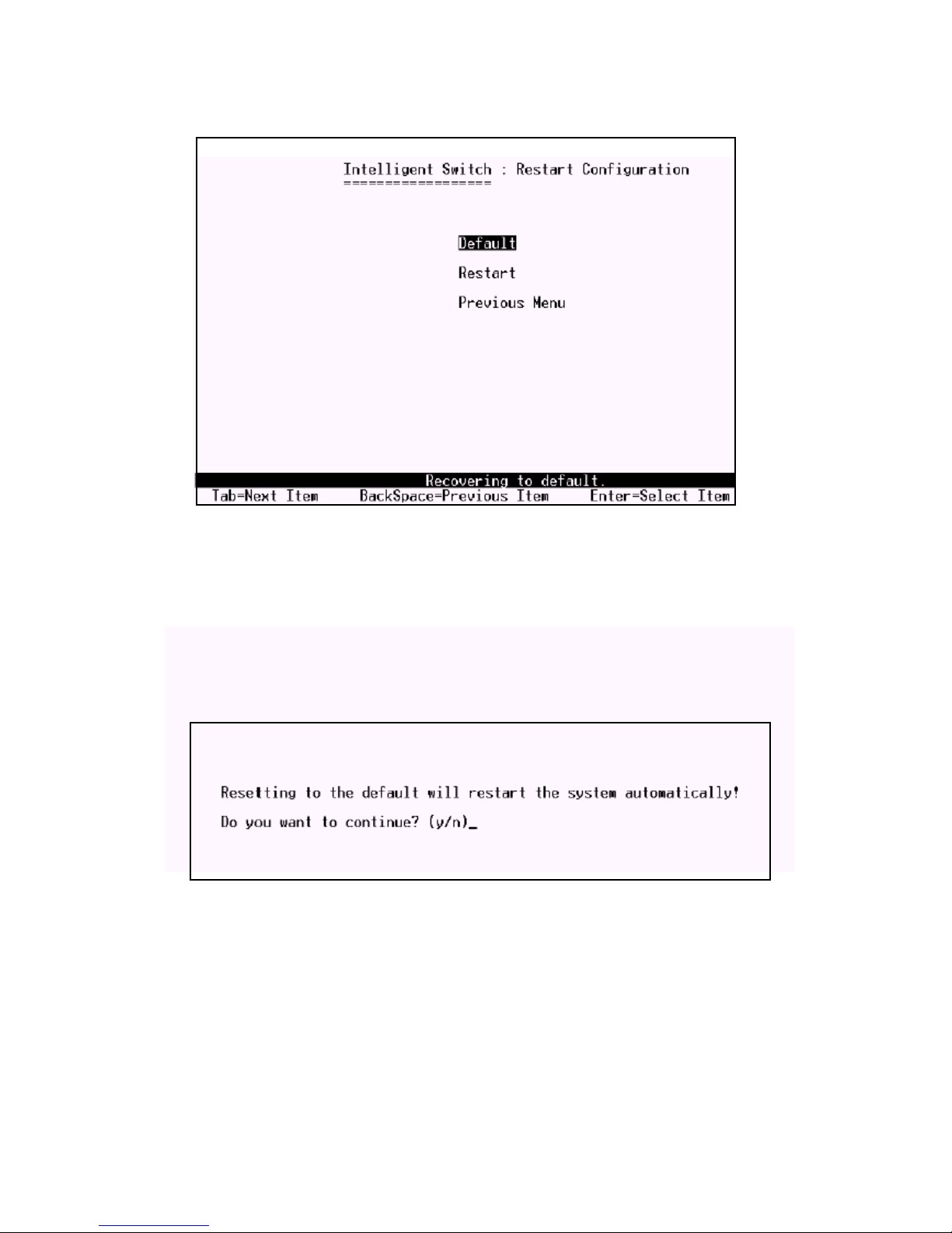
9. Reboot Switch
9.1 Default
Reset switch to default configuration.
9.2 Restart
Reboot the switch in software reset.
&&
Page 94
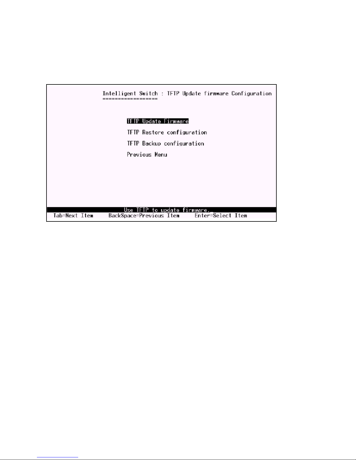
10. TFTP Update Firmware
This page provides you to update firmware or restore EEPROM value or upload current EEPROM
values.
10.1 TFTP Update Firmware
This page provides you use TFTP to update firmware.
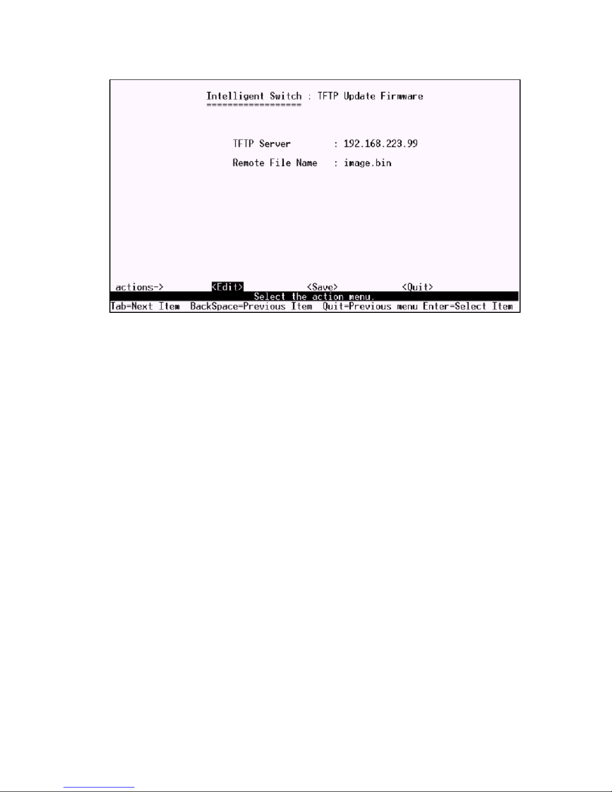
1. Start the TFTP server, and copy firmware update version image file to TFTP server.
2. Press <Edit> on this page.
3. TFTP Server: Type the IP of TFTP server.
4. Remote File Name: Type the image file name.
5. Press Ctrl+A to go back action line.
6. Press <Save> key, it will start to download the image file.
7. When save successfully, the image file download finished too.
8. Restart the switch.
&'
Page 95
'
Page 96
'
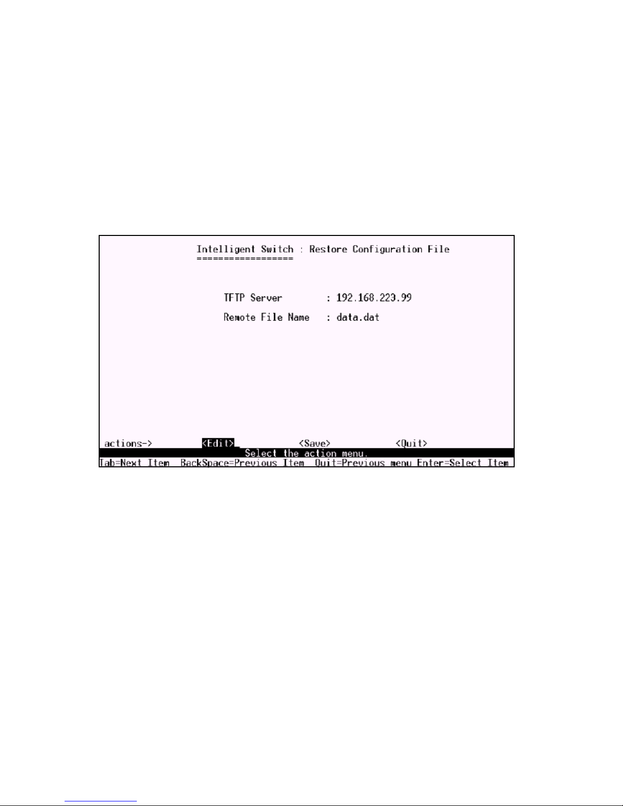
10.2 Update Configure File
In this page you can restore EEPROM values, save image file before, from TFTP server.
1. Start the TFTP server.
2. Press <Edit> on this page.
3. TFTP Server: Type the IP of TFTP server.
4. Remote File Name: Type the image file name.
5. Press Ctrl+A go to action line.
6. Press <Save> key, it will start to download the image file.
7. When save successfully, the image file download finished too.
8. Restart switch.
Page 97
10.3 Upload Configure File
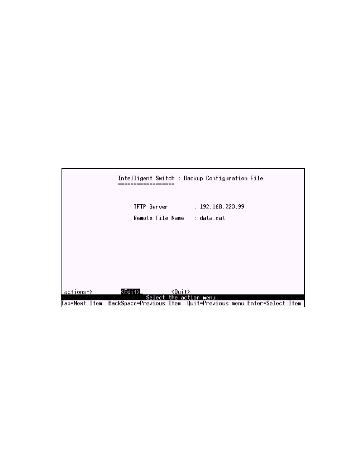
In this page you can save current EEPROM values to image file. Then go to the update configure page
to restore the EEPROM values.
1. Start the TFTP server.
2. Press <Edit> on this page.
3. TFTP Server: Type the IP of TFTP server.
4. Remote File Name: Type the image file name.
5. Press Ctrl+A go to action line.
6. Press <Save> key, it will start to upload the image file.
7. When save successfully, the image file upload finished too.
8. Restart switch.
'
Page 98

10.3.1 Trouble shooting
1. Power LED is not lit
Check if the power cord is properly connected to the power outlet and the switch. Make sure the
power switch at the rear panel is turned ON.
2. Link LED is not lit when connected to the network device
(1) Make sure the power switch of the network device is turned on
(2) Check if the network cable is properly connected to the switch and the network device
(3) Make sure the UTP cables comply with EIA/TIA 568 and Category 5 specification
3. Collision LED flashes constantly
(1) Remove all the network cables; connect the cables back one by one to isolate the source of the
collision.
(2) Check the network cable, inferior cable quality will result in excessive collisions and packet errors.
Contact your dealer if problems persist.
'!
 Loading...