

Page 1

Introduction
The EP-517T Hub
Congratulations on your purchase of the EP-517T Hub.
This user guide is provided to allow you to get the most
out of your new investment. It describes all features
and covers installation and operating instructions of the
EP-517T in an easy-to-read yet thorough manner.
Package Contents
The EP-517T package contains the following items:
One EP-517T Hub
•
One AC Power Adapter
•
One BNC T-Connector
•
This Manual
•
Four pieces of Rubber Foot
•
Two pieces of Tapping Screw
•
Two pieces of Nylon Screw Anchor
•
Features Overview
Your EP-517T Hub includes the following features:
Interconnects one 10BASE2 segment and
•
sixteen 10BASE-T link segments
IEEE 802.3 10BASE2 and 10BASE-T
•
compliant
Either the BNC or RJ-45 port as the cascading
•
port
Port auto-partitioning and reconnection to facili-
•
tate faulty segment isolation
Polarity auto-detection and auto-correction for
•
UTP/STP ports
Data collision and jabber handling functions
•
Two LEDs per port to indicate Link, Receive,
•
and Partition status
Two LEDs to indicate Power and Collision
•
status
1 32
The illustrations that follow depict the various external
components of the hub.
Figure 1
1. Power (RED) Indicator
When the power LED is lit, it indicates that the
hub's power is on.
2. Collision (YELLOW) Indicator
This LED indicator blinks when the hub detects a
collision on the network.
3. Link (GREEN) Indicators
These LEDs Indicator light green when the respective connection is okay.
4. Receive (GREEN) Indicators
A blinking LED to indicate data is being received
on the segment.
5. Partition (RED) Indicators
These LEDs light to indicate the port on the hub is
malfunctioning. Faulty ports are automatically isolated by the hub. When the port recovers, however,
the partition LED returns to normal status.
Wall Mounting
After you have decided on a suitable location for
mounting the hub, mark the location for inserting two
screws 242.5mm apart. At the marked locations, drill
two holes and insert a nylon screw anchor in each hole.
Insert a tapping screw in each hole. Align wall-mount
slots of the hub with the screws and slide the hub down
until the screws are securely fastened to the hub. You
can now complete the installation procedure by marking the necessary cable connections.
Figure 2
1. RJ-45 UTP/STP Ports
The hub is equipped with 16 RJ-45 UTP/STP ports
for making 10BASE-T hub-to-workstation connections.
2. Cascade Enable Slide-Switch
Slide this switch to the right to enable cascading
with straight UTP/STP cables.
3. AC Adapter Port
Plug the AC adapter jack into this port.
4. BNC Port
The hub is equipped with one BNC port for
making 10BASE2 hub-to-workstation connections.
Making Network Connections
The EP-517T hub has sixteen RJ-45 connectors for attaching up to sixteen 10BASE-T based workstations.
To establish such connections:
1. Ensure that both the hub and the soon-to-be-connected workstation are in the power off mode.
2. Plug one end of the UTP/STP cable into an
available 10BASE-T hub port.
3. Plug the other end into the workstation's network
interface card. The following figure 3 illustrates
a simple network topology via using a 10BASE-T
hub-to-workstation connections.
The EP-517T hub has one BNC port for making
10BASE2 hub-to-workstation connections. To establish
such connections:
Technical Writer: Project Leader: R&D Engineering Manager: R&D Vice Director: Customer Check:
Page 2
1. Ensure that both the Hub and the soon-to-be-connected workstation are in the power off mode.
2. Plug one end of the coaxial cable into the BNC
port of the Hub. Please refer to figure 3 if you are
having trouble locating this port.
3. Connect the other end of the coaxial cable to the
workstation's BNC connector located on the network interface card. Please refer to figure 3 for an
illustration of such a connection.
Note: If port1 (BNC PORT) does not connect to the
coaxial cable after power is applied to the hub, port1
(BNC PORT) is indicated by flashing of the RED LED.
The port1 LED does not flash after connecting the
cable to port1 and using the hub.
The following diagram illustrates 10BASE-T and
10BASE2 network connections.
Figure 3
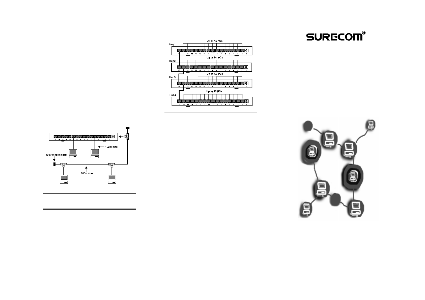
Cascading Hubs
When your 10BASE-T network needs to grow past the
sixteen available UTP/STP connections provided by the
hub, you should consider purchasing an additional hub
and cascading it with the original hub.
The EP-517T features a cascade enable switch. This
switch allows you to use straight UTP/STP cables instead of the traditional cables when cascading hubs.
The following diagram illustrates 10BASE-T cascading.
Figure 4
Federal Communications
Commission Statement
This equipment generates, uses, and can radiate radio
frequency energy and, if not installed and used in accordance with the instructions, may cause harmful interference to radio communications. This equipment
has been tested and found to comply with the limits for
a class A computing device, pursuant to Part 15 of the
FCC rules. These limits are designed to provide reasonable protection against harmful interference when
operated in a commercial environment. Operation of
this equipment in a residential area is likely to cause
interference, in which case the user, at his own expense,
will be required to take whatever measures are necessary to correct the interference.
CE Declaration of conformity :
This equipment complies with the requirements relating to electromagnetic compatibility, EN 55022 class
A for ITE and EN 50082-1, the essential protection requirements of Council Directive 89/336/EEC on the
approximation of the laws of the Member States relating to electromagnetic computability.
C471517T01ZZ0
54
EP-517T
Ethernet Hub
QUICK INSTALLATION
GUIDE
For the
Ethernet 10BASE-T 16-Port
Hub
 Loading...