

Page 1

EP-516DX-T/EP-524DX-T
16/24-Port 100/10M
Dual-Speed Hub
Users Manual
www.surecom.com.tw
#471516DXT030
Size: 14 cm x 20.5 cm (WxL)
Material: Cotton paper( ) 100pounds
www.surecom-net.com
Page 2

FCC Statement
This equipment can generate, use and radiate radio frequency energy and, if not
installed and used in accordance with the instructions in this manual, may cause
interference to radio communications. This equipment has been tested and found to
comply with the limits for a Class A computing device pursuant to Part 15 of the FCC
rules, which are designed to provide reasonable protection against radio interference
when operated in a commercial environment. Operation of this equipment in a
residential area is likely to cause interference, in which case the user, at his own
expense, will be required to take whatever measures are necessary to correct the
interference.
CE Declaration of Conformity
This is a Class A product. In a domestic environment product may cause radio
interference in which case the user may be required to take adequate measures.
© Copyright 1999 SURECOM Technology Corp. All rights reserved. No part of this
documentation may be reproduced , translated, adapted in any form without the
permission from the publisher.
Trademarks
All other brands and product names may be registered trademarks or trademarks of
their respective holders.
Table of Contents
Chapter 1 Introduction 1-1
Product Description 1-1
Key Features 1-3
Package Contents 1-3
Chapter 2 Hardware 2-1
Front Panel 2-1
LED Indicators 2-2
Rear Panel 2-3
Chapter 3 Quick Installation 3-1
Rack-Mount Installation 3-1
Connecting to an Additional Hub 3-3
Hub-to-Hub Uplink 3-5
Hub to End-Station Connection 3-6
Application 3-7
Appendix A Specifications A-1
Appendix B Troubleshooting B-1
iii
Page 3
1-1
Introduction
16/24 Port 100/10M Dual-Speed Hub is designed to allow easy migration
and integration between 100Mbps Fast Ethernet and 10Mbps Ethernet. It
means 100Mbps and 10Mbps users can communicate in the same network
environment. It also offers the simplest way to upgrade your network so that
you can connect all of your Fast Ethernet and Ethernet hosts to any hub in the
series, without any rewiring requirement when a host is upgraded from
10Mbps to 100Mbps.
16/24 Port 100/10M Dual-Speed Hub supports one optional 100BASE-FX
Fiber Optic Module (ST/SC-type) that can deliver a low cost yet high speed
data link over fiber, allowing you to expand your networks further than ever
before. The optional Fiber Optic Module can exceed the 100-meter limitations of Cat 5 UTP/STP cables, providing greater security and reliability.
The Dual-Speed Hub can be stacked up to 3 units for a total port count of 48
(or 72) connectors for workstations or servers.
n Powerful Performance
As your network grows, you need more bandwidth to stay productive and
competitive. Whether you are building a new network or expanding an
existing one, the Dual-Speed Hub gives you more power with the ease of
plug & play. A full 100Mbps link can be provided to all devices on the
LAN if required.
List of Figures
Figure 2.1 Front Panel of 16-Port Dual-Speed Hub 2-1
Figure 2.2 Front Panel of 24-Port Dual-Speed Hub 2-1
Figure 2.3 LED indicators of 16-Port Dual-Speed Hub 2-2
Figure 2.4 LED indicators of 24-Port Dual-Speed Hub 2-2
Figure 2.5 Rear Panel of 16-Port Dual-Speed Hub 2-3
Figure 2.6 Rear Panel of 24-Port Dual-Speed Hub 2-4
Figure 3.1 Attaching Brackets 3-2
Figure 3.2 Attaching to a Mounting Rack 3-2
Figure 3.3 Cascaded via an Uplink Port 3-3
Figure 3.4 Rack Mount Hubs ( 16-Port ) 3-4
Figure 3.5 Rack Mount Hubs ( 24-Port ) 3-4
Figure 3.6 Application 3-7
iii
1
Page 4
Key Features
q Conforms with IEEE 802.3 10BASE-T and 802.3u 100BASE-TX/
FX standards
q Supports 16 (or 24) RJ-45 Shielded Twisted-Pair ports and Uplink
function
q One optional Fiber optic module to upgrade Hub for Fiber connector
q 100/10Mbps Dual-Speed supported on each port with Auto-sensing
capability
q Embedded bridge module allows 100Mbps and 10Mbps segments
to intercommunicate transparently
q Provides Master, Power, Collision, Link/RX, Utilization, 100M,
FDX, and Partition LED indicators for network status
q Expansion bridge port supports 100BASE-TX ( Uplink Port ) distance
extension up to 100 meters, and 100BASE-FX ( Fiber Port ) distance
extension up to 2km in FDX mode
1-2
1-3
Package Contents
√ One 16/24 Port 100/10M Dual-Speed Hub
√ One Power Cord
√ One Warranty Card
√ One Stack Cable
√ One pack of screws
√ Two Mounting Brackets
√ This Users Manual
Note: If any of these items are damaged or missing, please contact
your supplier for replacement.
n Dual-Speed Hub
The Dual-Speed Hub has built-in bridge module, thereby providing
100Mbps and 10Mbps users transparent access to the same network, even
though the 100Mbps and 10Mbps segments are separated.
n Expansion bridge port function
The Dual-Speed Hub with the internal switching function can be
Auto-configured either Master mode or Slave mode. The master mode
occurs when a stack in port isnt connected on the rear panel. The slave
mode occurs when a stack in port is connected on the rear panel.
Therefore, the Dual-Speed Hub changes to either Master mode with one
expansion bridge port ( # 1 port ) or slave mode with two expansion bridge
ports ( # 1, 9 ports for 16 Port Dual-Speed Hub ; # 1, 13 ports for 24 Port
Dual-Speed Hub ) automatically depends on stack configuration.
n Optional Fiber Optic Module
The Dual-Speed Hub includes a module slot which can be
configured with fiber module to expand the network size and to connect
within a fiber cabled environment. With this optional fiber optic module
installed, data transmissions are not affected by electrical interference and
the distance of the link can be 208 meters to another hub or 412 meters
(2000 meters in FDX mode) to a switching hub.
Page 5
This chapter describes the front panel, LED indicators, and rear panel of
the 16/24 Port 100/10M Dual-Speed Hub.
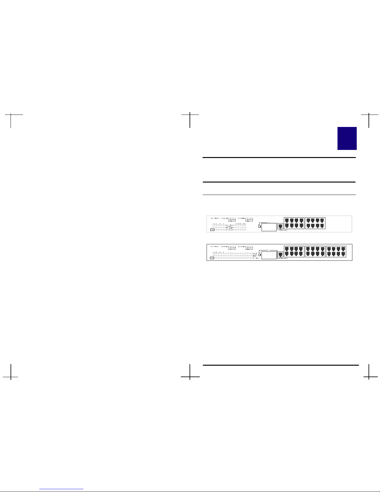
Figure 2.1 Front Panel of 16-Port Dual-Speed Hub
1. Fiber Optic Slot
To provide a wide range of connectivity options (ST/SC-type). Shared
with the port #1.
2. Uplink Port
Shared with the port #1 for expanding to another hub or switch.
3. RJ-45 Port
1~16 (or 24) 100/10Mbps ports for connecting to servers, workstations
or other devices.
4. FDX-Switch
Switch with Fiber Module in FDX/HDX mode.
2-1
This page was intentionally left blank.
2
Hardware
Front Panel
Note: The Fiber Optic Slot, Uplink port, and the port #1 share with
the same port. Ensure you do not use them at the same time.
The front panel of the Dual-Speed Hub consists of 16 (or 24) (100/
10Mbps) ports, 1 Fiber Optic Slot and 1 Uplink ports.
Figure 2.2 Front Panel of 24-Port Dual-Speed Hub
9 10 11 12
1234 5678
13 14 15 16
16151413121110
1234 9
10 11
125678
13
14 15 16
17 23 2419 20 21 23 22
24
23222120191817
Page 6
2-2
The LED indicators of the Dual-Speed Hub includes Master, Power
Collision, Link/RX, Utilization, 100M, and Partition.
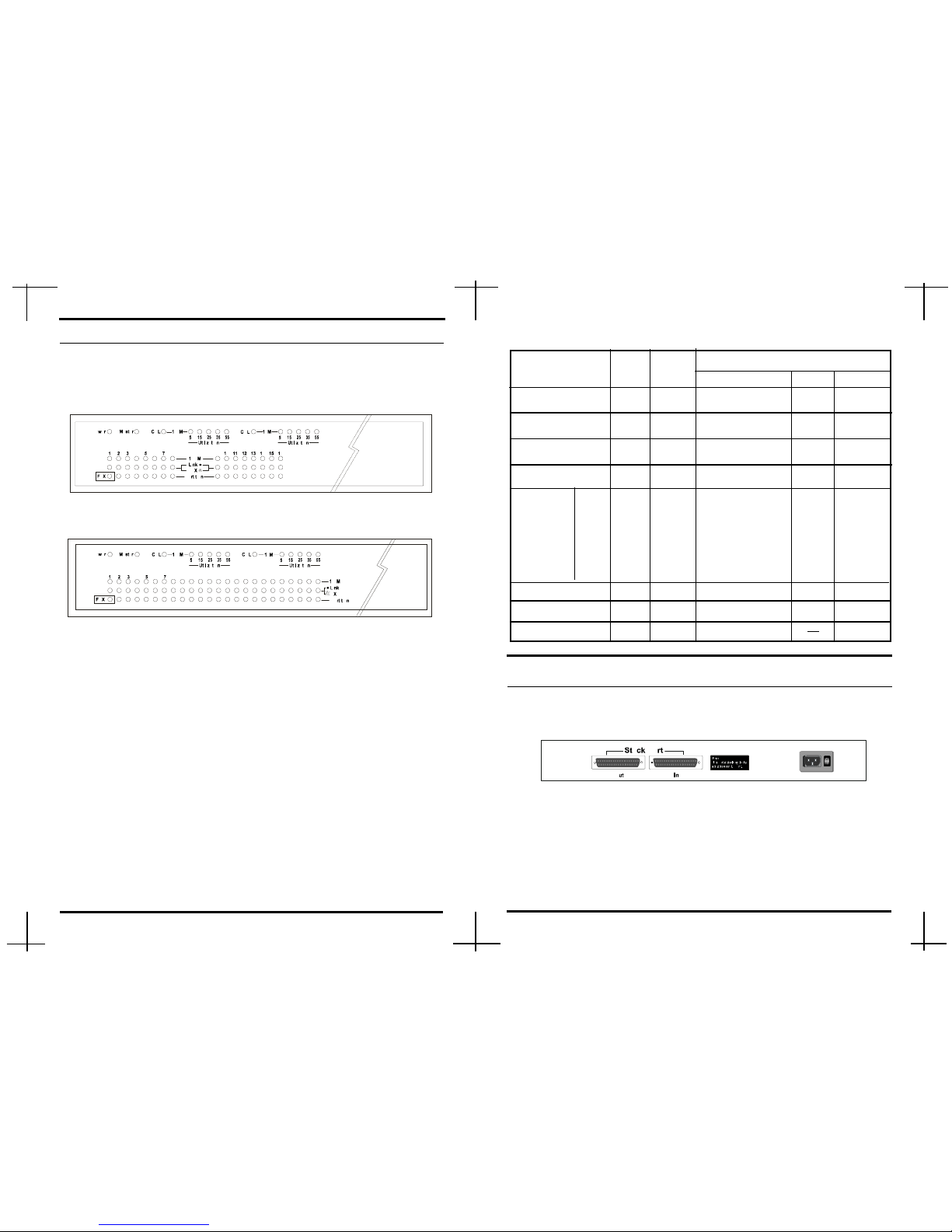
Figure 2.3 LED indicators of 16-Port Dual-Speed Hub
Master The LED is ON when the device is master mode.
Power The LED is ON when the Hub is turned on.
Collision The LED is ON when the collision is occurred.
Link/RX The LED is ON when the Hub is connected.
The LED is flashing when the data is received.
Utilization These LEDs display the utilization percentages in 5%,
15%, 25%, 35%, and 55%.
100M The LED is ON when the linking status is at 100Mbps.
Partition The LED is ON when a port on the Hub is malfunc-
tioning. The faulty ports are automatically isolated by
the Hub. When the port recovers, however, the Partition
LED will return to the normal status.
Function
on flash off
LED Indicators
Total
Number
Figure 2.4 LED indicators of 24-Port Dual-Speed Hub
♦ LED Indicators of 16-Port Dual-Speed Hub
LED Color
Master Green 1 Master Mode
¢w¢w
¢w¢w
¢w
Slave mode
Power Green 1 Power on
¢w¢w
¢w¢w
¢w
Power off
Collision Yellow 2 Collision
¢w¢w
¢w¢w
¢w
¢w¢w
¢w¢w
¢w
Link/RX Green 16 Link
RX
¢w¢w
¢w¢w
¢w
Partition Red 15 Partition
¢w¢w
¢w¢w
¢w
¢w¢w
¢w¢w
¢w
FDX Green 1 FDX mode HDX mode
Utilization
100M Green 16 100Mbps
¢w¢w
¢w¢w
¢w
11
11
1
00
00
0
MM
MM
M
bb
bb
b
pp
pp
p
ss
ss
s
5% Green 2 5% Traffic load
¢w¢w
¢w¢w
¢w
¢w¢w
¢w¢w
¢w
15% Green 2 15% Traffic load
¢w¢w
¢w¢w
¢w
¢w¢w
¢w¢w
¢w
25% Green 2 25% Traffic load
¢w¢w
¢w¢w
¢w
¢w¢w
¢w¢w
¢w
35% Yellow 2 35% Traffic load
¢w¢w
¢w¢w
¢w
¢w¢w
¢w¢w
¢w
55% Red 2 55% Traffic load
¢w¢w
¢w¢w
¢w
¢w¢w
¢w¢w
¢w
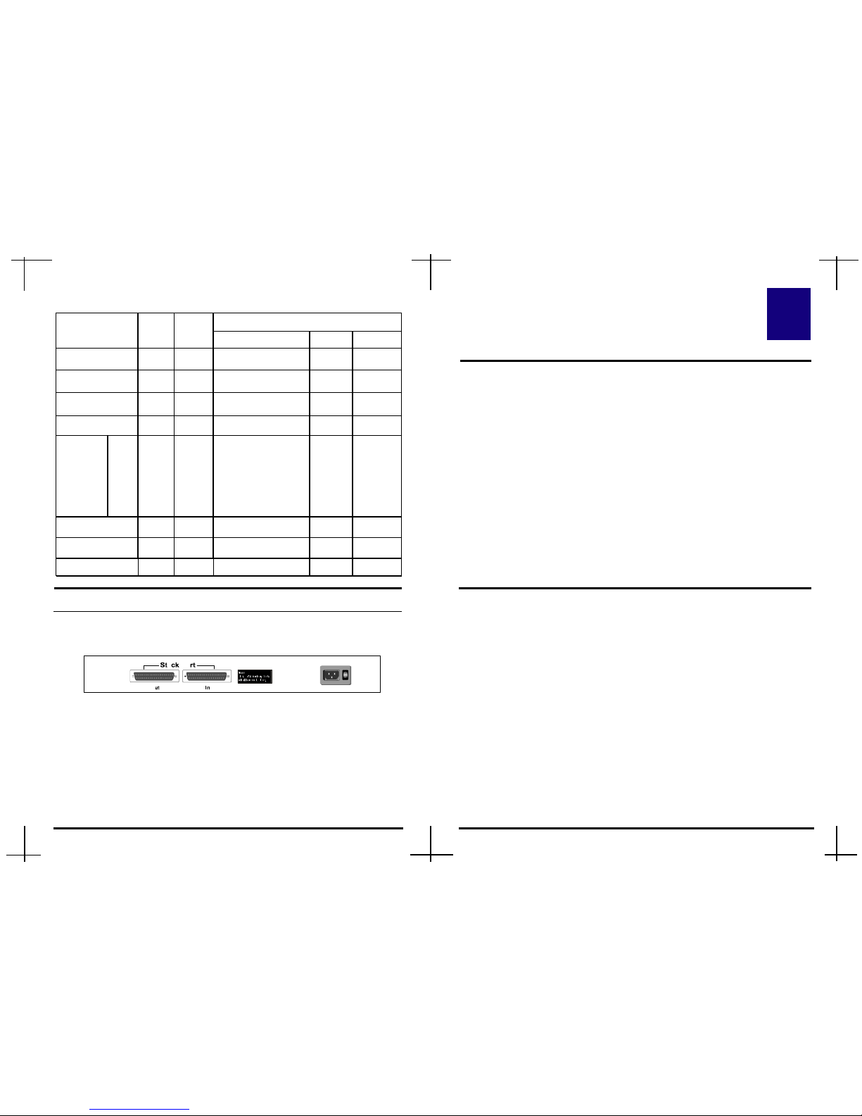
Rear Panel
The rear panel of 16 Port Dual-Speed Hub consists of Stack Port, Power
Socket, and Power Switch.
Figure 2.5 Rear Panel of 16-Port Dual-Speed Hub
Stack Port To connect two hubs and build 100M and 10M devices
working together.
Power Socket Plug the power cord into this socket.
Power Switch To turn the power on or off.
16151413121110 17 23 2419 20 21 23 22
2-3
Page 7
3-1
CHAPTER 3
Network DIY
3
This is an abbreviated installation procedure. We assume that you are
familiar with installing and using the Hub.
Rear Panel
The rear panel of 24 Port Dual-Speed Hub consists of Stack Port, Power
Socket, and Power Switch.
Figure 2.6 Rear Panel of 24-Port Dual-Speed Hub
Stack Port To connect two hubs and build 100M and 10M devices
working together.
Power Socket Plug the power cord into this socket.
Power Switch To turn the power on or off.
2-4
♦ LED Indicators of 24-Port Dual-Speed Hub
5% Green 2 5% Traffic load
¢w¢w
¢w¢w
¢w
¢w¢w
¢w¢w
¢w
15% Green 2 15% Traffic load
¢w¢w
¢w¢w
¢w
¢w¢w
¢w¢w
¢w
25% Green 2 25% Traffic load
¢w¢w
¢w¢w
¢w
¢w¢w
¢w¢w
¢w
35% Yellow 2 35% Traffic load
¢w¢w
¢w¢w
¢w
¢w¢w
¢w¢w
¢w
55% Red 2 55% Traffic load
¢w¢w
¢w¢w
¢w
¢w¢w
¢w¢w
¢w
Total
Number
Function
on flash off
LED Color
Master Green 1 Master Mode Slave mode
Power Green 1 Power on
¢w¢w
¢w¢w
¢w
Power off
Collision Yellow 2 Collision
¢w¢w
¢w¢w
¢w
¢w¢w
¢w¢w
¢w
Link/RX Green 24 Link
RX
¢w¢w
¢w¢w
¢w
Partition Red 23 Partition
¢w¢w
¢w¢w
¢w
¢w¢w
¢w¢w
¢w
FF
FF
F
DD
DD
D
XX
XX
X
GG
GG
G
rr
rr
r
ee
ee
e
ee
ee
e
nn
nn
n
1 FDX mode
Utilization
100M Green 24 100Mbps
¢w¢w
¢w¢w
¢w
11
11
1
00
00
0
MM
MM
M
bb
bb
b
pp
pp
p
ss
ss
s
Quick Installation
Step 1 Unpacking the package
Step 2 Check package items
Step 3 Place the Hub on a table or the mounting rack
Step 4 Plug the UTP/STP cable to both connected devices:
the Hub and the workstations/servers
Step 5 Attach the power cord to the Hub and then plug it into a
power outlet. We recommend the use of a surge suppressor.
Rack-Mount Installation
16/24-Port 100/10M Dual-Speed Hub comes with two brackets and six
screws for rack mounting at standard 19 mounting rack. Before you install
the Hub, please make sure your operating environment, including power
adapter, sufficient space, and proximity to the other network devices that are
to be connected.
Step 1 Choose a suitable location for mounting the hub.
Step 2 Insert screws into each hole on the bracket and anchor to
each side of the Hub, as shown in Figure 3.1.
¢w¢w
¢w¢w
¢w HDX mode
¢w¢w
¢w¢w
¢w
Page 8

3-2
3-3
Connecting to an Additional Hub
16/24-Port 100/10M Dual-Speed Hub can be connected to another
Dual-Speed Hub, or other Hubs.
Note:When the Uplink port is used, the port #1 will be unavailable.
♦♦
♦♦
♦ Cascaded via an Uplink Port
Step 3 Align the Hub to the rack, and secure it with the screws.
Make sure you slide the Hub down until the screws are
securely fixed to the Hub, as shown in Figure 3.2.
Figure 3.1 Attaching Brackets
Step 4 Now, you can now complete the installation procedure by
marking the necessary cable connections.
Figure 3.3 Cascaded via an Uplink Port
Figure 3.2 Attaching to a Mounting Rack
Server
16-Port Dual-Speed Hub
Series Stack
UTP/STP Cable
Workstations
Max .100 meters
Max. 100 meters
Max. 100 meters
16-Port Dual-Speed Hub
Page 9

3-4 3-5
Hub-to-Hub Uplink
You can link two Hubs or Hub stacks to each other using any of the
twisted-pair ports or the Uplink port. Ordinary twisted-pair ports require
crossover twisted-pair cables; linking one ordinary twisted-pair port and the
Uplink port requires an ordinary straight-through twisted-pair cable.
Expansion bridge port supports 100BASE-TX ( Uplink Port ) distance
extension up to 100 meters, and 100BASE-FX ( Fiber Port ) distance
extension up to 2km in FDX mode.
When connecting two Hubs or Hub stacks in this fashion, due to the increased
speed in Fast Ethernet and adherence to the EIA/TIA 568 wiring rules, the
maximum distance between any two end-stations in a collision domain is limited to 205 meters. In contrast, the maximum 10BASE-T Ethernet collision
domain can be up to 500 meters.
The following table describes different methods of linking Hubs (or Hub stacks):
♦♦
♦♦
♦ Stacked via Stack Ports
In a stack, 16/24-Port 100/10M Dual-Speed Hub can build up to 48 ( or 72 )
nodes, as shown in Figure 3.4.
Plug the stacking cable into the in port of the top hub and into the out port
of the next hub, then repeat this step for each hub in the stack. The link is
starting from the in port of the top hub and ending at the out port of the last
hub.
Stack 2 (Slave m od e)
Stack 3 (Slave m od e)
Stack 1(Master m o de)
Out In
Out In
In
Out
STACK PORT
STACK PORT
STACK PORT
Warning Label
Figure 3.4 Rack Mount Hubs ( 16/24 - Port )
Warning !
Owing to version differences, please stack with any other
hub which has this red warning label on it .
Never stack with any other hub without the warning
label on it.
faf
Page 10

Hub to End-Station Connection
After installing the Dual-Speed Hub, it can support up to 16 (or 24) endstation connections. Fast Ethernet connections require a Category 5 UTP/
STP cable. The cable can be up to 100 meters long.
Each Ethernet connection requires a Category 3 or better UTP cable. In order
to make an easier transition to 100Mbps for all nodes, we recommend you
install Category 5 cable for all connections.
You can connect any combination of PCs, servers, and other network devices
to the twisted-pair ports. Please use straight-through twisted-pair cables, dont
use crossover cables. The following figure illustrates the pin assignments for a
straight-through cable:
RD-
RD+
TD-
TD+
TD+
TD-
RD+
RD-
1
2
3
6
1
2
3
6
Straight-through Cable
Workstation (MDI)
Hub (M D I-X)
Application
Figure 3.6 Application
3-6
3-7
100 meters
100 meters
100 meters
100 meters
100 meter
16-Port Dual-Speed Hub
16-Port Dual-Speed Hub
Series Stack
Page 11
B-1
3---
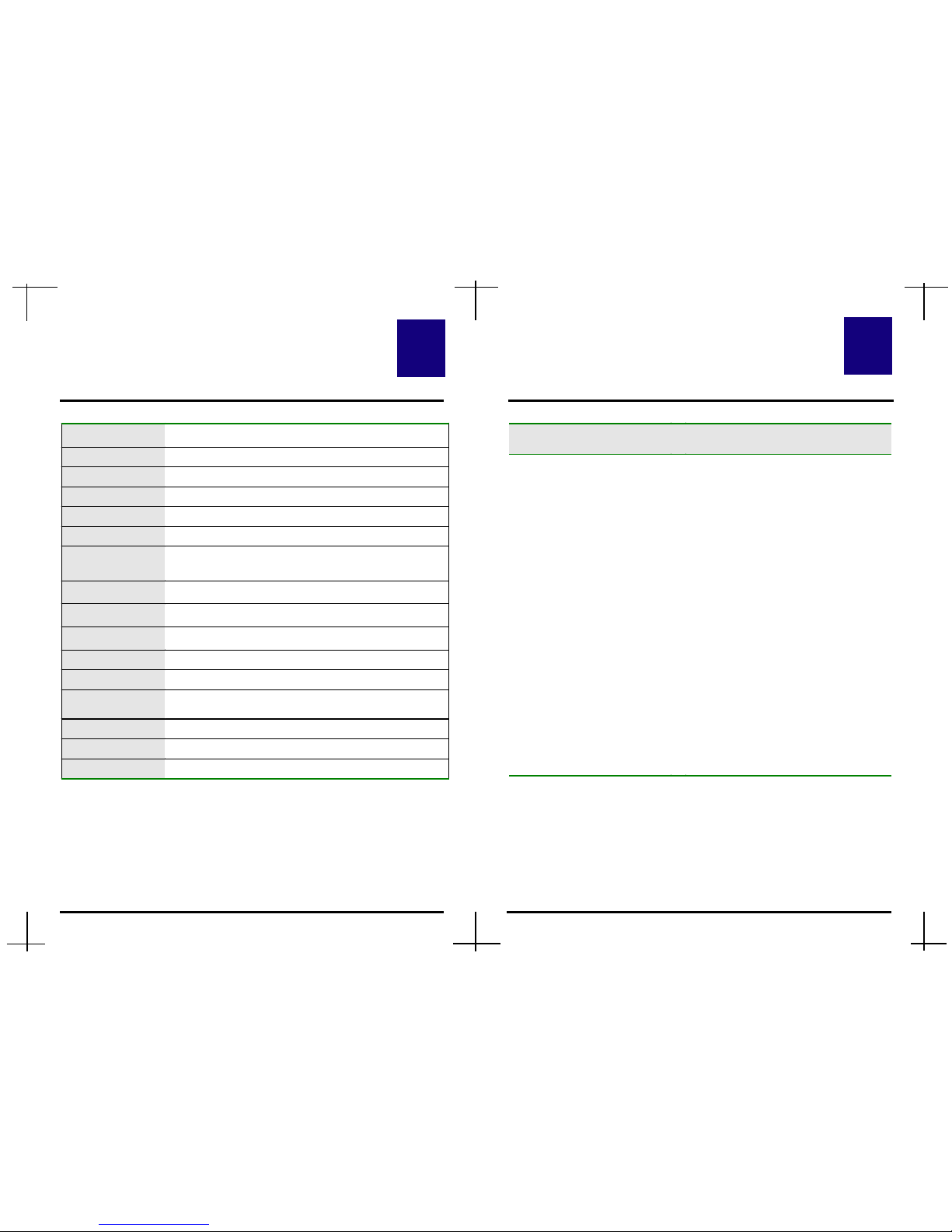
Specifications
Standard
IEEE 802.3 10BASE-T and 802.3u 100BASETX/FX
Access M ethod
CSMA/CD
STP Ports
16/24 100/10M ports with RJ-45 connectors
Fiber Port
One Fiber Optic Slot
U plink Port
One Uplink port
M ax. of a Stack
Up to 3 Hubs
M edia Support
Cat. 5 UTP/STP cable for 100BA SE-TX
Cat. 3 UTP/STP cable for 10BA SE-T
M ulti-mode fiber cable for 10 0B A S E -FX
M ax. Cable
Length
100 meters ( from H ub to Switch or Node)
M ax. Fiber
Cable Length
412 meters ( 2000 meters in FDX m ode )
LEDs
M aster, Pow er, Collision, L ink/R X, U tilization,
100M , Partition, and FDX.
Power Supply
Internal 100-250V A C
Dim ension
44.2 x 21 x 4 (W x D x H cm)
Net Weight
16-Port Dual-Speed Hub : 2560g
24-Port Dual-Speed Hub : 2950g
Temperature
5°C ~ 55°C (Operating) ; 0°C~ 65°C (Storage)
Humidity
10% ~ 90% (Operating) ; 5% ~ 95% (Storage)
Conformance
FCC Class A, CE
A B
Troubleshooting
Symptom Solution
Power indicator does not
light up (green) after power
on.
Step 1. Check the power cord by
plugging into another device
and see if it is functioning
properly.
Step 2. If these measures fail to
resolve the problem, have the
power supply replaced by
your supplier.
The LEDs show off after
cable is connected.
Step 1. Make sure you are connected
to the Hub.
Step 2. Verify that the other end of
the UTP/STP cable is
connected to the Hub which
is powered on and on-line.
Step 3. Check the UTP/STP cable is
connected to RJ-45 port not
the Uplink port.
A-1
4
 Loading...