

Page 1
®
User Manual
CM-METER-01
Package Contents
• RF Signal Meter
• 110 AC Power Adapter
• Rubber Antenna
• 24” SMA to N Cable Connectors
• 4 AAA Rechargeable Batteries
• User Manual
Safety Information
This equipment has been tested and found to comply with the limits for a class B digital device,
pursuant to part 15 of the Federal Trade Commission (FCC) Rules. These limits are designed to
provide reasonable protection against harmful interference in a residential installation. This
equipment generates, uses and radiates frequency energy, and, if not installed and used in
accordance with the instructions, may cause harmful interference to radio communications.
However, there is no guarantee that interference will not occur in a particular installation. If this
equipment does cause harmful interference to radio or television reception, which can be
determined by turning the equipment off and on, the user is encouraged to try to correct the
interference by one or more of the following measures:
---Reorient or relocate the receiving antenna
---Connect the equipment into an outlet on a circuit different from that to which the receiver is
connected
---Consult the dealer or an experienced radio/TV technician for help
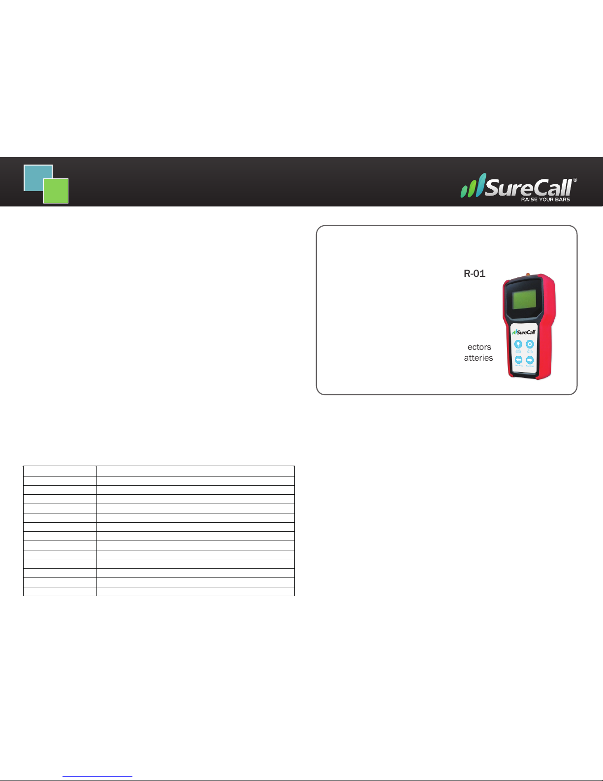
SureCall Five-Bands RF Signal Meter
Warranty
1. Cellphone-Mate, Inc. warrants to the buyer that each of its products, when shipped will be free from defects
in material and workmanship and will perform in full accordance with applicable specifications. The limit of
liability under this warranty is, at Cellphone-Mate, Inc.’s option, to repair or replace any product or part thereof
which shall within TWO YEARS of purchaseas determined by examination by Cellphone-Mate, Inc., prove
defective in material and/or workmanship. Warranty returns must first be authorized in writing by
Cellphone-Mate, Inc. Disassembly of any Cellphone-Mate, Inc. product by anyone other than an authorized
representative of Cellphone-Mate, Inc. voids this warranty in its entirety. Cellphone-Mate, Inc. reserves the right
to make changes in any of its products without incurring any obligation to make the same changes on previously
delivered products.
2. As a condition to the warranties provided for herein, the Buyer will prepay the shipping charges for all products
returned to Cellphone-Mate, Inc. for repair, and Cellphone-Mate, Inc. will pay the return shipping with the
exception of product returned from outside the United States in which case the Buyer will pay the shipping
charges.
3. The Buyer will pay the cost of inspecting and testing any goods returned under the warranty or otherwise which
are found to meet the applicable specifications or which are not defective or not covered by this warranty
4. Products sold by Cellphone-Mate, Inc. shall not be considered defective or non-conforming to the Buyers’
order if they satisfactorily fulfill the performance requirements that were published in the product specification
literature, or in accordance with samples provided by Cellphone-Mate, Inc. This warranty shall not apply to any
products or parts thereof which have been subject to accident, negligence, alteration, abuse, or misuse.
Cellphone-Mate, Inc. makes no warranty whatsoever in respect to accessories or parts not supplied by it.
5. EXCEPT AS EXPRESSLY SET FORTH HEREIN, THERE ARE NO WARRANTIES, CONDITION GUARANTEES OR
REPRESENTATIONS AS TO MERCHANTABILITY, FITNESS FOR A PARTICULAR PURPOSE OR OTHER WARRANTIES,
CONDITIONS, GUARANTEES OR REPRESENTATIONS, WHETHER EXPRESSED OR IMPLIED, IN LAW OR IN FACT,
ORAL OR IN WRITING. CELLPHONE-MATE, INC.’S AGGREGATE LIABILITY IN DAMAGES OR OTHERWISE SHALL NOT
EXCEED THE PAYMENT, IF ANY, RECEIVED BY CELLPHONE-MATE, INC. FOR THE UNIT OF PRODUCT OR SERVICE
FURNISHED OR TO BE FURNISHED, AS THE CASE MAY BE, WHICH IS THE SUBJECT OF CLAIM OR DISPUTE. IN NO
EVENT SHALL CELLPHONE-MATE, INC. BE LIABLE FOR INCIDENTAL, CONSEQUENTIAL, OR SPECIAL DAMAGES,
HOWSOEVER CAUSED.
6. All matters regarding this warranty shall be interpreted in accordance with the laws of the State of California
and any controversy that cannot be settled directly shall be settled by arbitration in California in accordance with
the rules then prevailing of the American Arbitration Association, and judgment upon the award rendered may
be entered in any court having jurisdiction thereof.
7. If one or more provisions provided herein are held to be invalid or unenforceable under applicable law, then
such provision shall be ineffective and excluded to the extent of such invalidity or unenforceability without
affecting in any way the remaining provisions hereof.
www.surecall.com
888.365.MATE (6283) phone - (510)996-7250 fax
48346 Milmont Drive , Fremont, CA 94538 (USA)
Frequency
Downlink:728 -746/746-757/869-894/1930-1990/2110-
2155MHz
Input Impedance
50 ohm
Max. Gain Shown
-40dBm
Standard Supported
LTE Verizon/LTE AT&T/Cellular/PCS/AWS
Receive Sensivity
-110dBm
Tolerance
<3dB
AC Power Transformer
Input AC110V, 60Hz; Output: DC5V
DC Power
4 AAA Rechargeable Baeries
Power Consumpon
<1.5Was
RF connector
SMA Female
Cable
RG174
Working Time
Dimensions
6.3*3.3*1.3 inch
Weight
205g
Stanby: 3.5 hours / Acve: 2.5 hours
CM-METER-01 2013 v 1.1
Page 2
The CM-Meter-01 RF signal meter by Cellphone-Mate provides accurate information of radio frequency
signals. The device can receive the RF signal from air an installed outdoor antenna or connects directly
to the field antenna. This device works with LTE, Cellular, PCS and AWS bands. The purpose of the RF
Signal meter is to assist in the installation of a Signal Booster, specifically for mapping the frequency
environment, pointing directional antennas, and maximizing signal booster coverage.
Features
• Five bands: 700 & 800 & 1900 & 2100MHz-(LTE, Cellular, PCS and AWS)
• High Receiving Sensitivity -110dBm
• Three selectable modes
• Controllable backlight for dark environments
• Rechargeable design with four AAA batteries
• Long working time (2.5 - 3.5 hours)
• Easy to carry
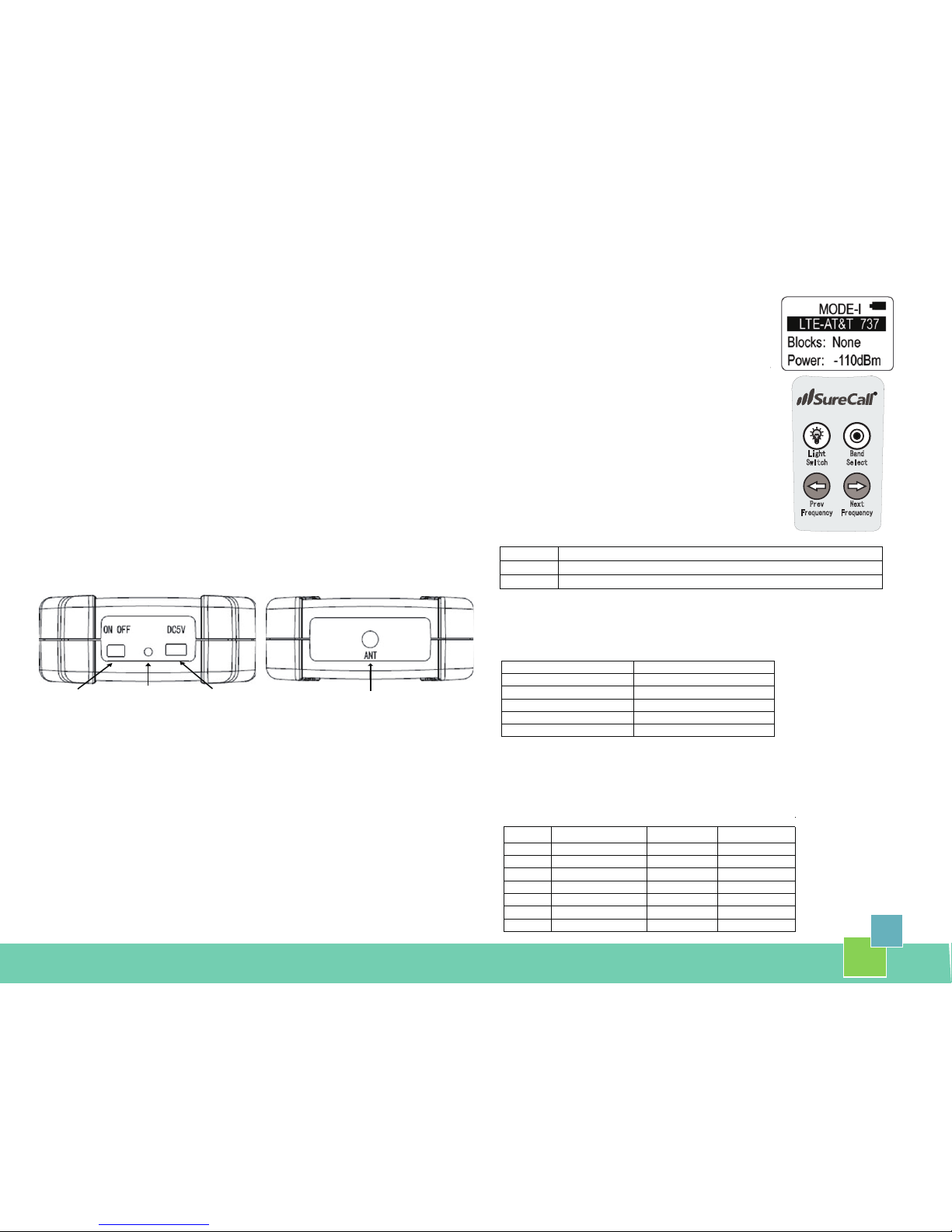
Turning on and Charging the Meter
The power switch is used to turn on/off the device. The power supply interface is a mini USB interface.
You can plug the AC power supply or any power source marked DC5V into it. Make sure that the power
source can provide over 1 amp of current.The charging light is a green LED. When it is plugged in and
the power switch is OFF, the LED will continue to blink while it is being charged. If the AAA batteries are
fully charged, the LED will blink once. When the charging is finished, the LED will stay lit.
Understanding the Screens
There are four lines of information available to users:
The top line displays detecting mode (see table 1, below) and
battery life
The second line displays detecting band
The third line displays detecting block in Mode-I, detecting
frequency in Mode-II and detecting band’s frequency range in
Mode-III.
The fourth line displays the detected dBm.
Note: Cellular signal reading is reflected in a negative number.
The lower the negative number, the stronger the signal.
Power
Mini-USB
LED charging
Using and Installing the Antenna and Antenna Interfaces
Antenna
The included antenna is used to pick up an outside RF wireless signal to determine its strengths and
weaknesses of each band to determine an ideal location to install outside antennas, for example. To
attach, screw antenna jack clockwise at top of meter.
Antenna Interfaces
The included 9” and 24” SMA-Male to N-Male pigtail cable connectors are used to gauge the best
outside RF wireless signal for installing or adjusting a directional outside antenna.
Step 1: Attach the SMA end of either included cable connector to the SMA antenna jack on the top of
the signal meter.
Step 2: Attach the N-male end of the cable connector to the N-female cable attached to the outside
directional antenna.
WARNING: Attaching the cable connectors from the meter to a cellular amplifier can permanently
damage your signal meter. If you wish to measure signal from the meter to amplifier, contact tech
support at support@cellphone-mate.com to find out how.
SMA Antenna and Cable
Bottom View Top View
Understanding the Keypad
There are four keys for user actions (see keypad example above)
The Light Switch button has two functions:
1. To turn the backlight ON or OFF, press quickly once.
2. To change the detection mode, press the button for a longer
period of time.
Below is a list of what the three modes represent
Note: Mode-III is likely to be used most by consumer or first-time
installers
Mode-I
Detects the power strength of one frequency block
Mode-II
Detects the power strength of one frequency point with 5MHz band
Mode-III
Detects the total frequency power strength of one band
Table 1 – Downlink Bands
The Band Select button will select between downlink bands.
Note: For a list of band options see table 2, following.
Table 2
The “Prev Frequency” button will switch to the previous frequency in Mode-II or previous block in
Mode-I.
The “Next Frequency” button will switch to the next frequency in Mode-II or next block in Mode-I.
“Prev Frequency” and “Next Frequency” buttons do not work in Mode-III.
Blocks CELLULAR 800(MHz)
PCS
1900(MHz)
AWS 2100(MHz)
A
869 ~880
1930 ~1945
2110 ~2120
B
880 ~890
1950 ~1965
2120 ~2130
C 1975 ~1990
2130 ~2135
D 1945 ~1950
2135 ~2140
E 1965 ~1970
2140 ~2145
F 1970 ~1975
2145 ~2155
G 1990 ~1995
Band Designaon
Frequency Range(MHz)
LTE-AT&T 737
728 ~ 746
LTE-VERIZON 751
746 ~ 757
CELLULAR 800
869 ~ 894
PCS 1900
1930 ~ 1995
AWS 2100
2110 ~ 2155
R
Prev
Frequency
Next
Frequency
Band
Select
Light
Switch
 Loading...