

Page 1
®
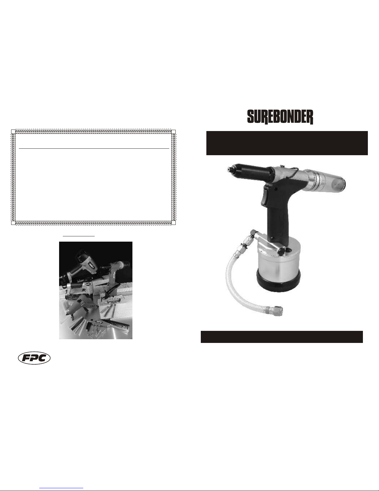
FPC835M
Air Hydraulic Rivet Tool
Read All Safety Rules and Instructions Carefully
Save this manual for Future Reference
Operating Instructions
FPC Corporation - 355 Hollow Hill Drive - Wauconda, IL 60084
Phone: (847) 487- 4583 Fax: (847) 487-0174
website: www.surebonder.com e-mail: [email protected]
0708
WARRANTY
If you have any problems with this tool, please call FPC Corporation
toll-free at 1-800-860-3838 before returning it to the place of purchase.
FPC Corporation warrants this product to be free from defects in material and
workmanship, under normal conditions of use and when used in accordance with
FPC operating instructions, for a period of 90 days from the date of purchase by the
user. Within the 90 day warranty FPC at its option shall repair or replace product.
The product must be returned at the distributor/user expense, either within
warranty or out. Repaired or replaced products will receive a 60 day warranty.
Visit us at surebonder.com for our full line of products
Page 2
THE SAFETY WARNINGS BELOW CANNOT COVER ALL POSSIBLE SITUATIONS THAT MAY
OCCUR. THESE BASIC SAFETY PRECAUTIONS SHOULD ALWAYS BE FOLLOWED TO PROTECT
AGAINST PERSONAL INJURY TO THE OPERATOR OR OTHER PERSONNEL IN THE AREA, AS
WELL AS DAMAGE TO THE EQUIPMENT. READ AND UNDERSTAND THESE WARNINGS
BEFORE USING EQUIPMENT.
Keep tool away from children, and DO NOT allow children near work area. Do not allow
children or untrained personnel to handle this tool.
DO NOT operate this tool while tired, or under the influence of drugs, alcohol, or medication
that makes you drowsy.
Never point the tool at yourself or others - always assume that the tool is loaded, and proceed
with caution.
Wear safety glasses and ear protection. The operator and all personnel
in the work area must wear safety glasses that protect the front and
Side, to avoid eye injury. Ear plugs should be worn to avoid hearing damage.
Never use oxygen, bottled gas or any type of combustible fuel as a power source - it can
cause an explosion and serious injury.
Use an air hose that will withstand at least 150 psi, OR 150% of the maximum pressure of the
compressor.
(WARNINGS continued next page)
This manual contains important information about product safety.
Read and understand this entire manual before operating this tool.
IMPORTANT SAFETY WARNINGS:
! DANGER
1
ANSI Z87.1
10
Dia.
No.
Part
No.
Description
2 835M-2 "O" Ring
10 835M-10 "O" Ring
11 835M-11 TEFLON RING
13 835M-13 "O" Ring
14 835M-14 TEFLON RING
17 835M-17 "O" Ring
19 835M-19 "O" Ring
20 835M-20 "O" Ring
22 835M-22 "O" Ring
27 835M-27 "O" Ring
35 835M-35 "O" Ring
42 835M-42 "O" Ring
45 835M-45 "O" Ring
47 835M-47 "O" Ring
53 835M-53 "O" Ring
57 835M-57 LIP SEAL
59 835M-59 "O" Ring
64 835M-64 "O" Ring
65 835M-65 LIP SEAL
69 835M-69 "O" RING
Dia.
No.
Part
No.
Description
23 835M-23 PARTITION
24 835M-24 SILENCER
25 835M-25
NAIL CONTAINER
26 835M-26 COVER
27 835M-27 "O" Ring
28 835M-28 WASHER
29 835M-29 BOLT
Dia.
No.
Part
No.
Description
835M-420 AIR VALVE ASSEMBLY KIT
Parts not sold separately
835M-400 SEAL KIT
Parts not sold separately
835M-410 NAIL CONTAINER ASSEMBLY KIT
Parts not sold separately
35
835M-35
"O" Ring
36 835M-36
AIR INTERFACE
40 835M-40
AIR VALVE BODY
41 835M-41
AIR VALVE RING
42 835M-42
"O" Ring
43 835M-43
AIR VALVE BASE
44 835M-44
SUBORDINATE TUBE
45 835M-45
"O" Ring
46 835M-46
CONNECTING BASE
49 835M-49
AIR VALVE ROD
50 835M-50
SCREW PLUG
61 835M-61
TRANSFER TUBE
Required No
Part No.
Description
1 835M-314
3/32" NOSEPIECE
1 835M-414
1/8" NOSEPIECE
1 835M-514
5/32" NOSEPIECE
1 835M-614
3/16" NOSEPIECE
3 835M-3
OUTER CYLINDER
4 835M-4
JAW HOUSING
5 835M-5
JAW
6 835M-6
PUSHER
7 835M-7
SPRING
8 835M-8
UPPER HOUSING
9 835M-9
SET NUT
15 835M-15
PRIME AXIS
Dia.
No.
16 835M-16
RESTORE SPRING
18 835M-18
VACUUM SWITCH
21 835M-21
AIRPROOF LID
30 835M-30
HANDLE(LEFT)
31 835M-31
HANDLE(RIGHT)
32 835M-32
TRIGGLE
33 835M-33
TRIGGLE VALVE
34 835M-34
ON/OFF BASE
37 835M-37
RESTRAIN RING
38 835M-38
AIR TUBE
39 835M-39
TAPPING SCREW
48 835M-48
SWITCH ASSEM.
51 835M-51
SILENCER
52 835M-52
CYLINDER COVER
54 835M-54
BOLT
55 835M-55
LOCK NUT
56 835M-56
BUFFER
58 835M-58
AIR TUBE PISTON
60 835M-60
PISTON RING
62 835M-62
PISTON ROD
63 835M-63
CYLINDER PISTON
66 835M-66
BOLT
67 835M-67
CYLINDER
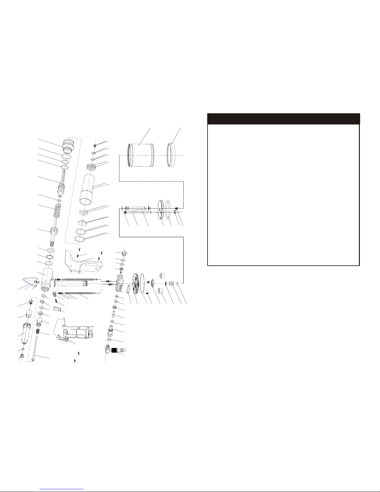
PARTS
Parts sold separately
11111111111111111111426111212111111
68 835M-68
BASE COVER
1
717069
835M-71
835M-70
835M-69
HOOK
OIL FILL SCREW
"O" RING
111
Part No.
Description
Required No
12 835M-12 OIL CYLINDER135 835M-35 "O" Ring136 835M-36 AIR INTERFACE169 835M-69 "O" RING170 835M-70 OIL FILL SCREW110 835M-10 "O" RING211 835M-11 TEFLON RING
1
Dia.
No.
835M-430 "T" SHAPE HOUSING ASSEMBLY KIT
Parts not sold separately
Required
No
.
1212112121422111111
1
Required
No.
1111111
Required No
22112112111
1
Call
8
4
-
4
8
7 5
83
t
o
rd
e
r
p
r
ts
an k
it
s
7
-4
o
a
d
Page 3
Disconnect air hose from tool:
-before performing maintenance.
-when clearing a jam.
-when tool is not in use.
-when moving it to another location.
Carry tool by the handle only, not by the air hose.
Inspect the tool before each use to insure all parts are operating properly. Lock the tool
in a clean, dry storage area between uses.
Only use parts and accessories supplied or recommended by FPC Corporation.
Unauthorized parts or fasteners can lead to malfunction and serious injury. Only
personnel trained by FPC Corporation or the distributor shall repair the tool. Do not
modify this tool in any way.
Do not store the tool in a cold weather environment. Keep the tool in a warm area until
the start of work. If it is in a cold area, bring it in a warm area and allow it to warm up
before use.
Manufacturer assumes no responsibility for consequential or indirect damages from the
use of this product.
Save this manual and have it available for tool operators
reference!
IMPORTANT SAFETY WARNINGS: continued
California Proposition 65
You can create dust when you cut, sand, drill or grind materials such as: wood,
paint, metal, concrete, cement, or other masonry. This dust often contains chemicals
known to cause cancer, birth defects or other reproductive harm. Wear protective gear.
2
1133
3311
4422
7700
0055
44664488
4477
3300
0066
0077
4040
5533
5544
5511
5522
5588
5599
5757
5566
5555
4433
4455 4444
4422 4411
4499
3355
3344
3388
3366
3377
3322
0088
0099
3333
11
11
6699
1122
00
0022
0033
0044
7711
2233
2255
6611
6622
6600
6633
6644
6655
6666
5500
4455
3399
1133
1155
1166
2288
2299
2266
2244
6688
6677
1188
2211
11
1144
1177
1199
1199
2222
2222
2277
2200
FPC
8
3 a
rt
s List5M
P
Page 4
3
8
APPLICATIONS
Installing 3/32', 1/8", 5/32" & 3/16" blind rivets in various materials in production/commercial
applications.
FEATURES
- Lightweight
- Air hydraulic operating system
- Use with or without mandrel collection
- Carrying Case, jaws and maintenance tools included
AIR SUPPLY
NEVER use oxygen or other bottled gases. Explosion may occur.
This tool is designed to operate on clean, dry, regulated compressed air, between 75 and 100
psi. It is preferable to include an air filter and pressure regulator within 15 feet of the tool, if
possible.
An air filter is needed to remove contaminates and moisture that are contained in compressed
air; filtering will significantly prolong the life of the tool. Do not install a quick coupler directly
into the tool. Higher pressure drastically reduces tool life.
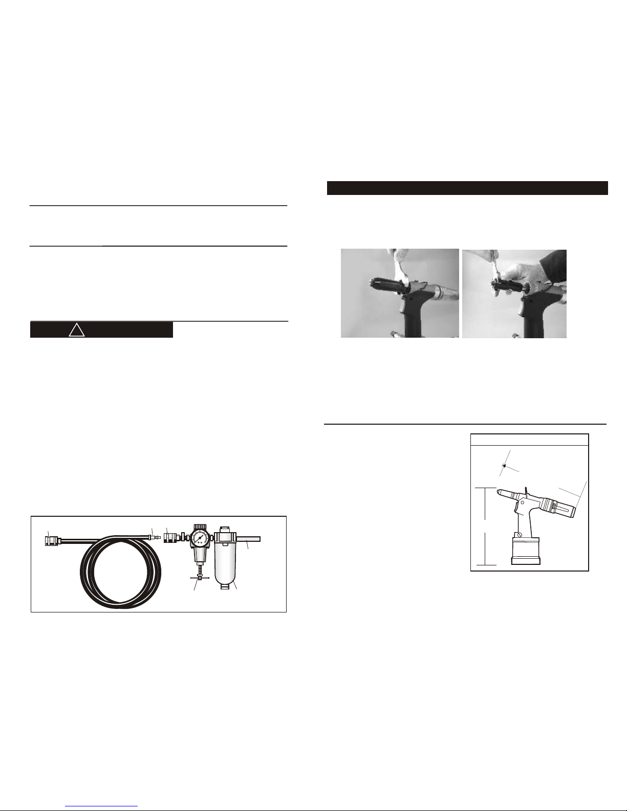
The tool comes factory-equipped with a male quick connector. The tool must always be
connected to the air supply with a coupling that removes all pressure when it is disconnected.
NOTE: all components used with this tool (air hose, connectors, regulators, filters, etc) must
be rated at 120 psi, OR 120% of the maximum compressor potential, whichever is higher. Do
not connect this tool to a system with maximum potential air pressure greater than 120 psi.
! DANGER
Head Cleaning and oiling
Every 10, 000 cycles the jaws of the tool should be cleaned and oiled. Disconnect the air
supply and air valve. To access jaws unscrew nosepiece then unscrew jaw guide. Jaws will
be loose in jaw guide.
Remove housing Remove jaw case
Clean jaws, jaw guide, jaw pusher, spring and thread area of the pulling head. Apply lubricant
to the outside surface of jaws and inside surface of the jaw guide. Reassemble the head by
placing the jaws into the jaw guide. Slide the spring and jaw pusher into the pulling head and
screw the jaw guide onto the pulling head.
20
0
40
60
80
100
120
140
160
Regulator Filter
To compressor
To Tool
Quick Connector Quick Coupler
AIR CONNECTION SET UP
SPECIFICATIONS
Overall Dimensions 11.75" x 10.500”
Stroke .787”
Air Pressure 75-100 PSI
Pull Force 1,872 lbs.
Weight of Tool: 3 lbs.
Sets: 3/32" , 1/8" , 5/32" , 3/16" Rivets
Dimensions
10.500"
1.36"
MAINTENANCE (continued)
.51
4
1
.7 0
"1
5
Page 5
OPERATION
OPERATION
5
6
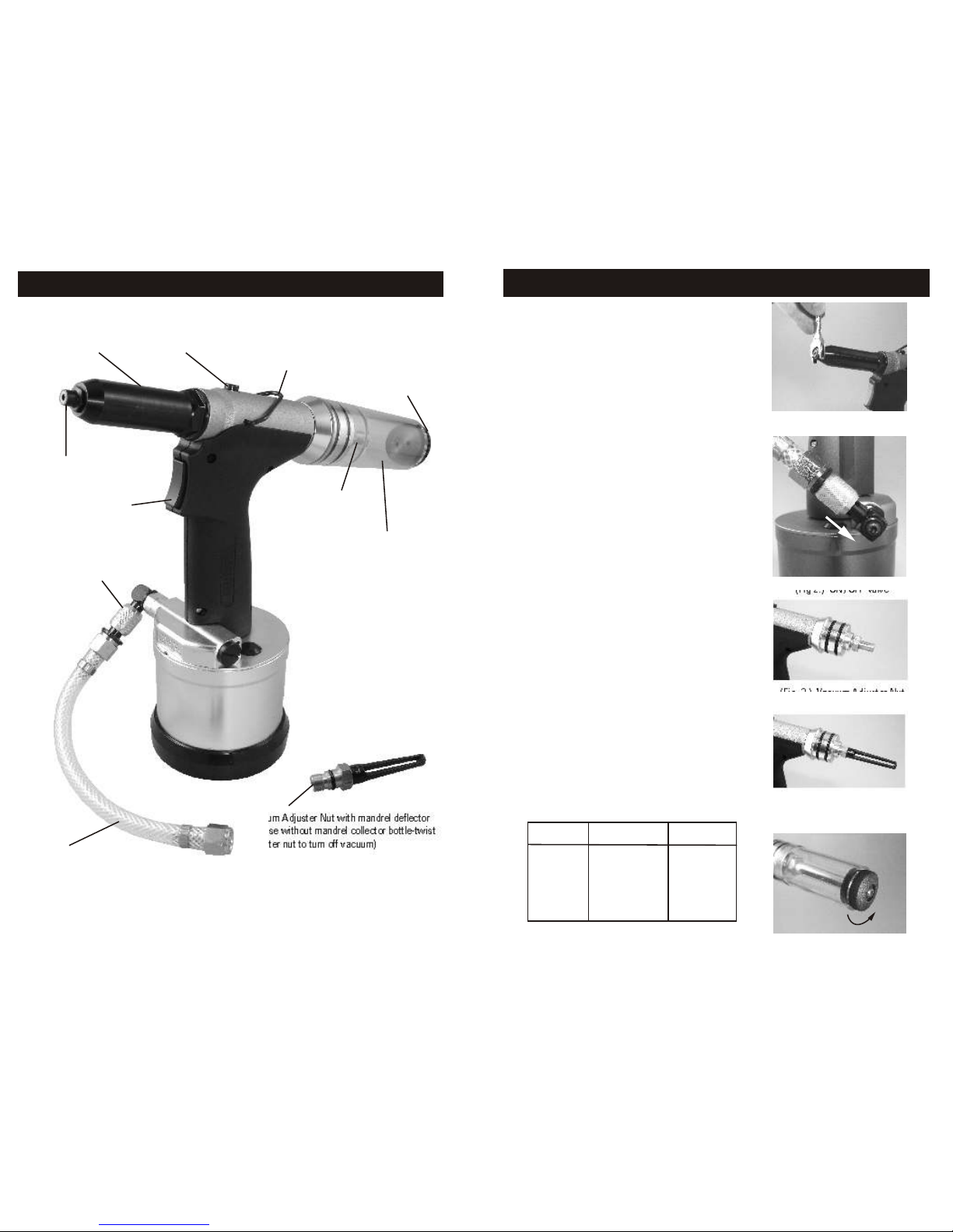
Part Identification
TOOL PREPARATION
Determine the size rivet that you are going to use. If
setting 3/16" rivets no changes to the tool are
necessary the 3/16” nosepiece is factory installed.
For 1/8” and 3/32” diameter rivets, the jaw pusher
tube must be removed and replaced. The smaller
diameter tube is included in your spare parts case.
To change the nosepiece remove it from rivet tool
using wrench included. Select nosepiece that
corresponds to the size rivet you are using and
screw nosepiece clockwise onto rivet tool head.
Attach air line to air supply. Turn on the air ON /
OFF valve by pushing the deflector ring on the air
connection down. ( Fig. 1.)
Insert a rivet mandrel into the nose piece. The rivet
will be held in place by the vacuum. If rivet falls out
of the nosepiece, vacuum is not strong enough. To
increase amount of suction turn vacuum adjuster
nut located on the back of the tool. (Fig. 3.) If
mandrel collector free operation is desired use the
vacuum adjuster nut with mandrel deflector
(included). (Fig.4)
Place the rivet into the hole until contact is made
between the face of the rivet head and the outer
surface to be riveted. (See chart below for correct
hole sizes to drill.)
Squeeze the trigger to set the rivet. Release the
trigger once the rivet is set. The spent mandrel will
be ejected into the mandrel collection bottle. Never
allow mandrel collection bottle to fill more than 1/3
full damage to the hydraulic plunger may occur. To
empty mandrel collection bottle pull from tool and
shake mandrels out of opening. Firmly push bottle
back onto tool.
Hanger
Oil Fill Screw
Nose Housing
Mandrel Collector
Exhaust
Mandrel Collector
Vacuum Adjuster Nut
Vacuum Adjuster Nut with mandrel deflector
(for use without mandrel collector bottle-twist
adjuster nut to turn off vacuum)
Nosepiece
Trigger
On / Off Valve
Flexible Air Hose
(Fig. 1.) Mandrel Changing
(Fig 2.) ON /OFF Valve
(Fig. 3.) Vacuum Adjuster Nut
for use w/ Mandrel Collection
(Fig. 4.) Vacuum Adjuster Nut
with deflector for mandrel
collector-free use
Adjustable Exhaust
Rivet Size Hole Size to Drill Drill Bit No .
3/32" .097"-.100" #41
1/8" .129"-.133" #30
5/32" .160"-.164" #20
3/16" .192"-.196" #11
Page 6
Lubrication
It is important that the tool be properly lubricated. Every 10,000 cycles the tool should be oiled with
lubricating oil. There may be insufficient oil if the stroke of the tool is too small for proper
installation. Without proper lubrication the tool will not work properly and parts will wear
prematurely.
1) Keep the tool upright during all operations. Disconnect the tool from the air supply.
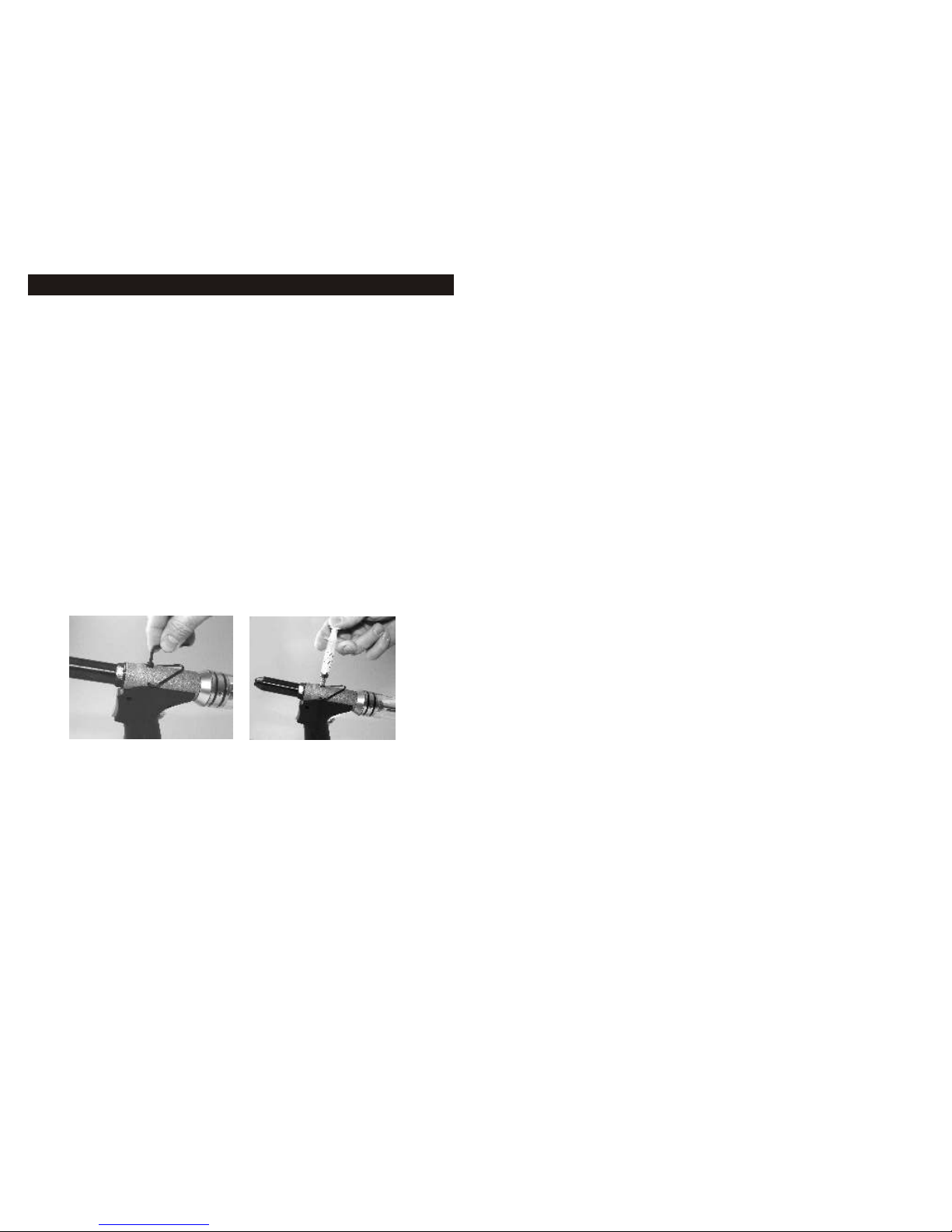
2) Unscrew the oil fill screw from the body using the allen wrench included. (Fig. 5.)
3) Fill the syringe (included) with hydraulic oil.
4) Screw the filled syringe in the oil fill screw hole. (Fig. 6.) Then slowly inject the oil into the tool
(Make sure no air is injected). Adequate oil has been added as soon as resistance is sensed.
The excess oil will flow back when the syringe is release if more oil is added than necessary.
5) Unscrew and remove the syringe from the body.
6) Screw the oil fill screw into the hole using the allen wrench.
7) Wipe off any excess oil.
To test oil level, reconnect rivet tool to air supply and depress trigger 2-3 times. insert rivet into
nosepiece (use the largest diameter rivet that tool accepts). Check to see if rivet mandrel can be
inserted completely into nosepiece - head of rivet must touch nosepiece. If rivet cannot be
completely inserted into tool, too much oil has been added and some must be removed. To remove
excess oil unscrew oil fill screw approximately 1/4 turn. Once the tool is properly adjusted tighten
the oil fill screw firmly with the allen wrench and wipe off any excess oil. When the oil fill screw is
unscrewed, oil will seep from the chamber. After the rivet mandrel is full seated into the nosepiece,
the oil level is then ready for operation.
(Fig. 5.) (Fig. 6.)
Servicing and Cleaning Jaws
To access jaws, remove nose housing to expose pulling mechanism and jaw case. To remove jaw
case from pulling mechanism, use 2 wrenches (included). Jaws will be under slight spring pressure
from the jaw pusher. Separate jaw case from pusher. Jaws will be loose. Clean jaws with a wire
brush. Place a small dab of multi-purpose Lithium grease or Lubriplate™ on outside of jaws (not
serrated side). Return jaws into jaw case ensuring proper placement of jaws. All serrated faces
should be touching each other.
Air Supply Requirements
Use a dry, filtered air supply regulated to 75 - 100 psi (5-6 bar) . A minimum of 3.0 scfm is
recommended. If the recommended operating pressure is exceeded the tool may not function
because of built up line pressure.
For optimum performance connect the tool air line to an air supply of at least 1/4". The 6"
lightweight hose included with the tool is designed to reduce operator fatigue by reducing
weight.
If problems should occur with the setting of the pressure, disconnect the tool from the
compressed air supply, to release pressure from the tool.
Mode of Operation
When the tool is connected to an air supply and the trigger is pulled, pressurized air pushes
the air piston which acts on the hydraulic ram assembly. The hydraulic ram assembly forces
hydraulic fluid from the reservoir in the handle into the main hydraulic bore where it moves
the hydraulic piston together with the attached pulling mechanism rearward. As the pulling
jaws move rearward they close on and grip the rivet mandrel and set the rivet.
When the trigger is released air at line pressure forces the hydraulic piston forward to the
starting position. As the hydraulic piston moves forward the hydraulic fluid is also forced
back returning the hydraulic fluid and the ram assembly and air piston to the starting
position. The compressed air used to set the rivet is exhausted through the base of the
intensifier chamber. When the hydraulic piston is fully returned the broken rivet mandrel is
released as the jaws are forced open again by the nosepiece.
7
4
MAINTENANCE
 Loading...