

Page 1
1697R Galaxy Head and Combo
User Manual
All contentsc2019 Absara Audio LLC
Page 2
1. Important Safety Information
The triangle surrounding an exclamation
mark alerts users to the presence of important warnings or information.
The triangle surrounding a lightning bolt
alerts users to the presence of dangerous
high-voltage within the enclosure of the
product that can pose a significant risk
of electrical shock.
• Read these instructions
• Keep these instructions
• Heed all warnings
• Follow all instructions
• Do not use this apparatus near water
• Clean only with dry cloth
• Do not block any ventilation openings. Install in accordance with the manufacturers
instructions.
• Do not install near any heat sources such as radiators, heat registers, stoves, or other
apparatus (including amplifiers) that produce heat.
• Do not defeat the safety purpose of the grounding-type plug. A grounding type plug
has two blades and a third grounding prong. The third prong is provided for your
safety. If the provided plug does not fit into your outlet, consult an electrician for
replacement of the obsolete outlet.
• Protect the power cord from being walked on or pinched particularly at plugs, convenience receptacles, and the point where they exit from the apparatus.
• Only use the attachments/accessories specified by the manufacturer.
• Use only the cart, stand, tripod, bracket, or table specified by the manufacturer, or sold
with the apparatus. When a cart is used, use caution when moving the cart/apparatus
combination to avoid injury from tip-over.
• Unplug this apparatus during lightning storms or when unused for long periods of time.
• Refer all servicing to qualified service personnel. Servicing is required when the appa-
ratus has been damaged in any way, such as power-supply cord or plug is damaged,
liquid has been spilled or objects have fallen into the apparatus, the apparatus has
been exposed to rain or moisture, does not operate normally, or has been dropped.
• To insure proper ventilation always make sure there is at minimum four inches (101.6mm)
of space behind the rear of the apparatus. The ventilation should not be impeded by
covering the ventilation openings with items, such as newspapers, tablecloths, curtains, etc. Do not impede ventilation by placing objects on top of the apparatus which
extend past the rear edge of its cabinet.
• Please contact Supro directly or a qualified person for tube replacement
• The AC plus is the mains disconnect. The plug should remain accessible after instal-
lation.
• WARNING: To reduce the risk of fire or electric shock, do not expose this apparatus
to rain or moisture.
• WARNING: The apparatus shall not be exposed to dripping or splashing and that
objects filled with liquid, such as vases, shall not be placed on apparatus.
• Caution: To reduce the risk of fire or electric shock, do not remove the cover or back
of the product. There are no user serviceable parts inside. Refer service to qualified
personnel.
1
Page 3

Contents
1 Important Safety Information 1
Contents 2
2 Anatomy and Usage 3
2.1 Front Panel . . . . . . . . . . . . . . . . . . . . . . . . . . . . . . . 3
2.2 Rear Panel . . . . . . . . . . . . . . . . . . . . . . . . . . . . . . . . 4
Speaker Outputs . . . . . . . . . . . . . . . . . . . . . . . . . . . . . 4
Footswitches . . . . . . . . . . . . . . . . . . . . . . . . . . . . . . . 5
Effects Loop . . . . . . . . . . . . . . . . . . . . . . . . . . . . . . . 5
Reverb . . . . . . . . . . . . . . . . . . . . . . . . . . . . . . . . . . 6
2.3 Tubes . . . . . . . . . . . . . . . . . . . . . . . . . . . . . . . . . . 8
2.4 Troubleshooting . . . . . . . . . . . . . . . . . . . . . . . . . . . . . 8
3 Supro Warranty Policy 9
3.1 USA/Canada Warranty . . . . . . . . . . . . . . . . . . . . . . . . . 9
3.2 International Warranty: . . . . . . . . . . . . . . . . . . . . . . . . . 10
2
Page 4
2. Anatomy and Usage
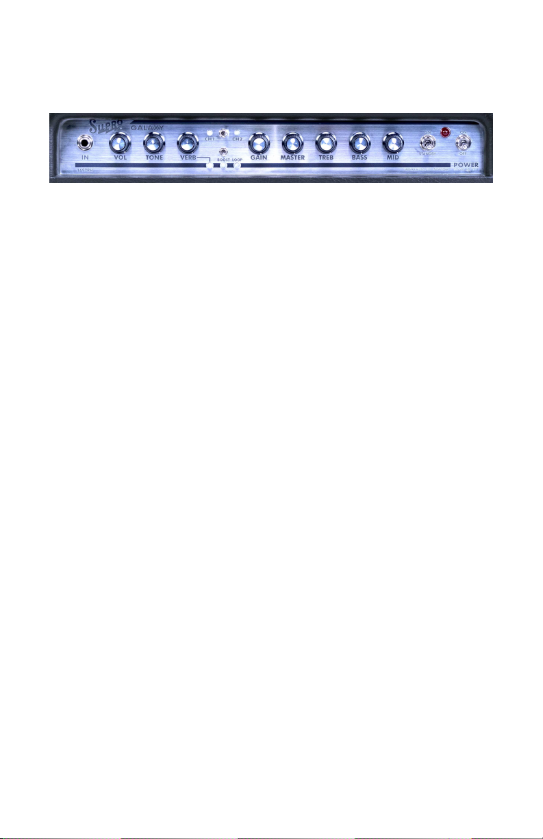
2.1 Front Panel
IN
Instrument input for the amplifier.
VOL
Controls the volume level of Channel 1.
TONE
The TONE control for Channel 1 is a passive Treble / Bass filter. Turning the
knob clockwise decreases bass response, while increasing treble. Turning the knob
counterclockwise decreases treble response, while increasing bass frequencies.
VERB KNOB & LED
Controls the amount of Reverb in the signal path. The LED indicates the status of
the Reverb. The Reverb can be assigned to Channel 1, Channel 2 or BOTH, via a
switch on the rear panel. Note: Reverb is active when LED is lit.
CH1 LED
Lights when Channel 1 is active.
CHANNEL SWITCH
Selects Channel 1 or Channel 2.
CH2 LED
Lights when Channel 2 is active.
BOOST SWITCH & LED
The Switch activates the Boost function. The BOOST function is on when the switch
is in the up position. Boost is active when LED is lit.
LOOP LED
Shows the status of the Effects Loop: Note: Loop is active when LED is lit.
GAIN
Controls the Gain of Channel 2.
MASTER
Controls the volume of Channel 2.
TREB
Controls the level of treble frequencies of Channel 2.
3
Page 5

BASS
Controls the level of bass frequencies of Channel 2.
MID
Controls the level of midrange frequencies of Channel 2.
STANDBY SWITCH
This turns on the high voltage to the tubes. The tubes should warm up for at least
one minute before turning standby switch to OPERATE. Be sure that the Volume
control is set to a reasonable position before switching the amp to OPERATE as this
amp can be very loud! For short breaks (5 minutes or less), using the standby switch
will increase tube life.
PILOT LIGHT
This shows that AC Mains voltage is flowing to the amplifier.
POWER SWITCH
Turns on AC power to the amp. The Power switch should be turned on, and the pilot
light should be lit for 1 minute before turning the standby switch to ON.
2.2 Rear Panel
IEC POWER CORD RECEPTACLE / Fuse holder
The power cord connects here and to your country’s appropriate wall outlet. Make
sure to connect the male end of the IEC POWER CORD into a Grounded Power
Outlet. This IEC connector contains the AC Mains fuse. This is a 5x20mm, 3A,
250V Fuse.
Speaker Outputs
The Galaxy provides two 4-Ohm, two 8-Ohm, and one 16-Ohm speaker output.
Which output jack you use, depends on the configuration of your speaker cabinet
or cabinets. For instance, when using a single 8 Ohm speaker, connect the speaker
cabinet to one of the 8 Ohm jacks. If using two 8-Ohm speakers or cabinets, plug
them both into the 4-Ohm jacks. (Two 8-Ohm loads connected in parallel add up
to a 4-Ohm total load). If using a 16-Ohm cabinet, plug it into the 16-Ohm output.
A speaker must always be connected to at least one output. Do not turn the
amp on without a speaker plugged in.
4
Page 6

Footswitches
Each footswitch jack is designed to accept a 1/4” TS cable, and single footswitch.
Your Galaxy is furnished with one SF1 footswitch. Additional footswitches may be
purchased through your local dealer or online at www.Suprousa.com
BOOST SWITCH JACK
Allows remote switching of the BOOST function. Insert a standard guitar cable, and
connect the other end to the one button footswitch included with your amplifier.
Note: Plugging into this jack will override the front panel BOOST switch function.
CHANNEL SWITCH JACK
Allows remote channel selection. Note: Plugging a cable into the CHANNEL footswitch
jack will override the front panel switch position
EFFECTS LOOP FOOTSWITCH JACK
Allows remote switching of the effects loop. Note: Plugging a cable into the LOOP
footswitch jack will override the rear panel switch position.
Effects Loop
The effects loop in the Supro Galaxy provides a place to insert effects after the gain
stages of the pre-amp.
SEND JACK
Sends signal to the input jack of external effects pedals.
RETURN JACK
Receives signals from the output of external effects pedals.
EFFECTS LOOP ENGAGE SWITCH
Engages or disengages the effects loop. Note: This switch is overridden by inserting
a 1/4” cable in the ”LOOP” footswitch jack.
5
Page 7

Reverb
The Supro Galaxy is equipped with tube-driven, spring reverb.
DWELL
The Dwell knob allows you to set how much signal is fed to the Reverb pan when
Channel 2 is activated. Turning the Dwell knob counter-clockwise reduces the signal
level going into the Reverb. This is helpful for balancing the reverb sound between
the two channels, especially when the Gain on Channel 2 is turned up.
CHANNEL ASSIGN SWITCH
Selects whether reverb is active on Channel 1, Channel 2, or Both.
REVERB FTSW
Allows remote shut-off of the reverb effects via a latching footswitch, using a 1/4”
TS cable.
6
Page 8

Input
Input Buffer
&
Boost
CH1
Tone
Stack
Tone
Stack
Send
Bypass
Return
Channel
Switching
Reverb Assign
Switch
(Rear Panel)
Reverb
Assign
CH2
Dwell
Active Summing
Amplifier
To Power Amplifier
Effects Loop
Footswitch
Effects Loop
Switch
(Rear Panel)
Reverb
Footswitch
Effects
Loop
Reverb Tank
Reverb
Driver
Reverb Gain
Recovery
Channel
Footswitch
Channel Switch
(Front Panel)
Boost
Footswitch
Figure 2.1: 1697R Galaxy Signal Flow Diagram
7
Page 9

2.3 Tubes
Viewed from the rear of the chassis
Power
Transformer
Output
Transformer
Power Tubes
6L6
6L6
ECC83
ECC83
ECC83
ECC832
ECC83
V1V3
V4
V5V6
V7
V8
CH1 PreampCH2 Preamp
Reverb Make-up
EFX Loop
ECC81
V2
Reverb Driver
CH2 PreampPhase Inverter
Each Supro tube amplifier is a 100% analog, 100% tube amplifier. There are NO
solid state (transistor) devices in ANY audio signal path.
2.4 Troubleshooting
Supro products have been designed for years of trouble free service. There are many
unique protection features to the design. If you are having difficulty, check the
following:
No sound, but PILOT LIGHT is ON
Check to see that the speaker is plugged into the SPEAKER JACK (not the footswitch
jack). Make sure all knobs are turned up past zero and that the standby switch is set
to operate. As this is a tube amp, the tubes take approximately 1 minute to warm
up before you will get sound. The STANDBY switch should be set to standby for
this warm up period.
No sound and the Lights are All OFF
Unplug the power cord and check the 2.5A, 250V fuse (rear panel).
If you have any further questions, our email address is info@suprousa.com.
8
Page 10

3. Supro Warranty Policy
3.1 USA/Canada Warranty
To Validate the Warranty on your Supro tube amplifier, please register the product online at
http://suprousa.com/warranty/.
This warranty applies only to the original retail purchaser when this amplifier is purchased
from an Authorized Supro Dealer and is subject to the limitations set forth herein.
Important: Please retain your original sales receipt, as it is your proof of purchase validating
this limited warranty.
This Warranty shall cover the following components as below:
• Amplifiers: 1 year, extended* to 2 years
• Speaker enclosures: 1 year, extended* to 2 years
• Tubes and Speakers: 90 days
*Note: The extended warranty will be automatically applied when you register online at
http://suprousa.com/warranty/. The extended warranty period is only applicable if the
above form is submitted prior to the expiration of the initial 1 year warranty which begins at
the date of purchase. It is your responsibility to submit this information and we shall not be
liable nor do we accept any responsibility whatsoever for non-receipt of this information.
What is Covered:
Defects in the materials and/or workmanship of your product which has been purchased
through an authorized Supro USA dealer. This Warranty shall be applicable when the original
sales receipt or proof of purchase of the Product is presented together with the defective
Product.
What is not Covered:
Damage caused by negligence, modification, improper use, incorrect voltages or general wear
and tear. Damage caused during transportation of the product. Damage caused by repair
or service carried out by persons not authorized by Supro USA. A Product with a serial
number which has been defaced, removed etc. A Product which was not purchased from an
Authorized Dealer in the USA or Canada.
Warranty Service:
The Warranty Service may include repairs or replacement of the Product in accordance with
the terms set out herein. If we are unable to repair the defective Product, we reserve the
right to provide you with a replacement which may or may not be a reconditioned Product.
Do not attempt to repair the device because this voids the warranty.
In the event a repair or replacement has been made, we shall be entitled to take and keep
possession of the defective Product which is deemed to be beyond repair during the Warranty
Period.
Providing the defective Product is covered by the terms of this Warranty we shall be responsible for the cost of returning your unit to you.
9
Page 11

How to Obtain Warranty/Non-Warranty Service:
• Complete the service email form available at
http://suprousa.com/support/.
• You will receive a Supro USA Return Authorization form from a Supro support technician.
• You must download, print and complete the Supro USA Return Authorization form.
Provide the info requested on this form, and include a copy of the original purchase
receipt. Please enclose these two documents with your amp, and ship to the Supro
USA service dept:
Supro USA
200 Wilson St. BLDG F
Port Jefferson Station, NY 11776
For amps owned less than 30 days, Supro USA will pay ground shipping both ways.
For amps owned over 30 days and less than 365 days, (except extended warranty, which will
be extend coverage for 2 years), customer pays shipping to Supro USA and Supro USA pays
return ground shipping. If amp is returned to Supro and proven to be oversight or user error,
customer will be responsible for return shipping.
For non-warranty service, customer pays return shipping both ways. Repair charges must be
paid within 60 days completion or it becomes property of SuproUSA.
3.2 International Warranty:
(for customers outside of the United States and Canada) Supro USA has chosen only the
best dealers and distributors to work.
1. Call the Supro dealer that you purchased your amplifier from. Inform them the nature of
the problem you are having. Most often they will be able to assist you with replacement
parts or service
2. If your dealer is unable to help, call the Authorized Supro Distributor in your country (you
can find their details on our site). They have the technical staff and experience to assist
you, and also have all of the resources of Supro engineers at their disposal
3. If you are still unable to get the assistance you require or you feel you have a problem
that the Distributor cannot resolve, contact us directly by sending an e-mail to sup-
port@suprousa.com, but only if you have tried both previous routes first.
10
 Loading...