

Page 1
NATIONAL
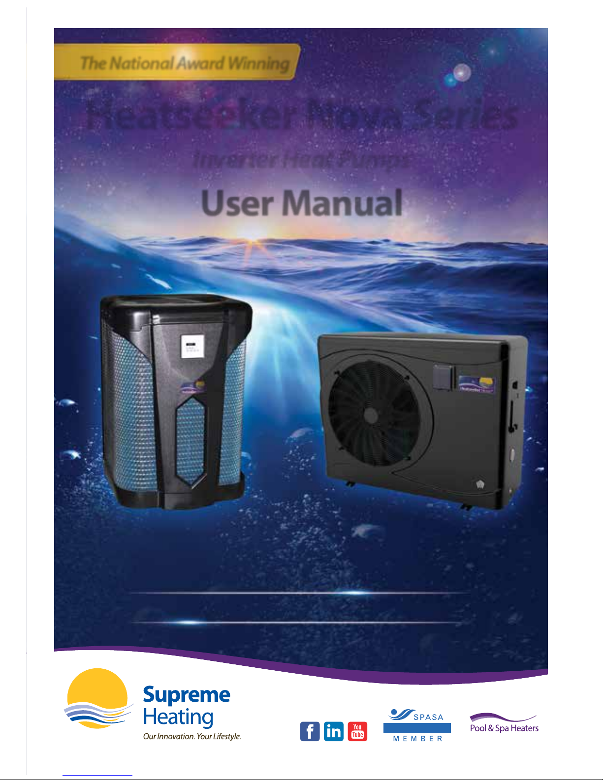
Heatseeker Nova Series
The future of heat pump technology has arrived
Nova
Awarded gold for sustainability
The National Award Winning
Heatseeker Nova Series
Inverter Heat Pumps
Nova
+
With even greater performance
User Manual
Page 2
supremeheating.com.au
1300 787 978
Head Oce
Bundoora
VIC 3083
P: (03) 9460 4200
info@supremeheating.com.au
NSW Oce
Smeaton Grange
NSW 2567
P: (02) 4648 4766
solar.nsw@supremeheating.com.au
salesnsw@supremeheating.com.au
QLD Oce
Yatala
QLD 4207
P: (07) 3807 6308
solarqld@supremeheating.com.au
SA Oce
Wingeld
SA 5013
M: 0437 947 375
solarsa@supremeheating.com.au
WA Oce
South Fremantle
WA 6162
P: (08) 9433 5588
solar@supremeheating.com.au
Page 3

GOLD AWARD
2015 NATIONAL
AWARDS OF
EXCELLENCE
Heatseeker Nova Series
Inverter Heat Pumps
01
General Information 02
Introduction to Heatseeker Nova Series 02
Consumer and Safety Information 03
Technical Specications 04
Heatseeker Nova Inverter Heat Pump 04
Dimensions 05
Heatseeker Nova Inverter Heat Pump 05
Technical Specications 06
Heatseeker Nova+ Inverter Heat Pump 06
Dimensions 07
Heatseeker Nova+ Inverter Heat Pump 07
Installation and Connection 09
Installation Safety Notes 09
Heat Pump Location 09
Distance from your swimming pool 10
Check Valve Installation 11
Typical Arrangement 11
Adjusting the Bypass 12
Electrical Connection 13
Cable Wiring 14
Initial Operation 15
Water Flow Switch 15
Time Delay 15
Condensation 16
Pressure Gauge Display (R410A) 16
Accessories 17
Accessories List 17
Installation of Accessories 17
Operation 18
Controller Overview 18
Power (On / O) 18
Mode Controls 18
Water Temperature Settings 19
Checking the Time 19
Setting the Time 19
Setting the Automatic Start Time 20
Setting the Automatic Stop Time 20
Checking the Parameters 21
Heat Pump Modes 23
Powerful Mode 23
Smart Mode 23
Silent Mode 23
Notes 23
System Reset Function 23
Troubleshooting - Heatseeker Nova 24
Error Code Displayed on LED Controller 24
Troubleshooting - Heatseeker Nova
+
26
Error Code Displayed on LED Controller 26
Other Malfunctions and Solutions - No LED Display 29
Maintenance 30
Warranty Agreement 31
Notes 33
User Manual
Heatseeker Nova Series Inverter Heat Pump
Published October 2017
Page 4
Heatseeker Nova Series
Inverter Heat Pumps
02
General Information
Introduction to Heatseeker Nova Series
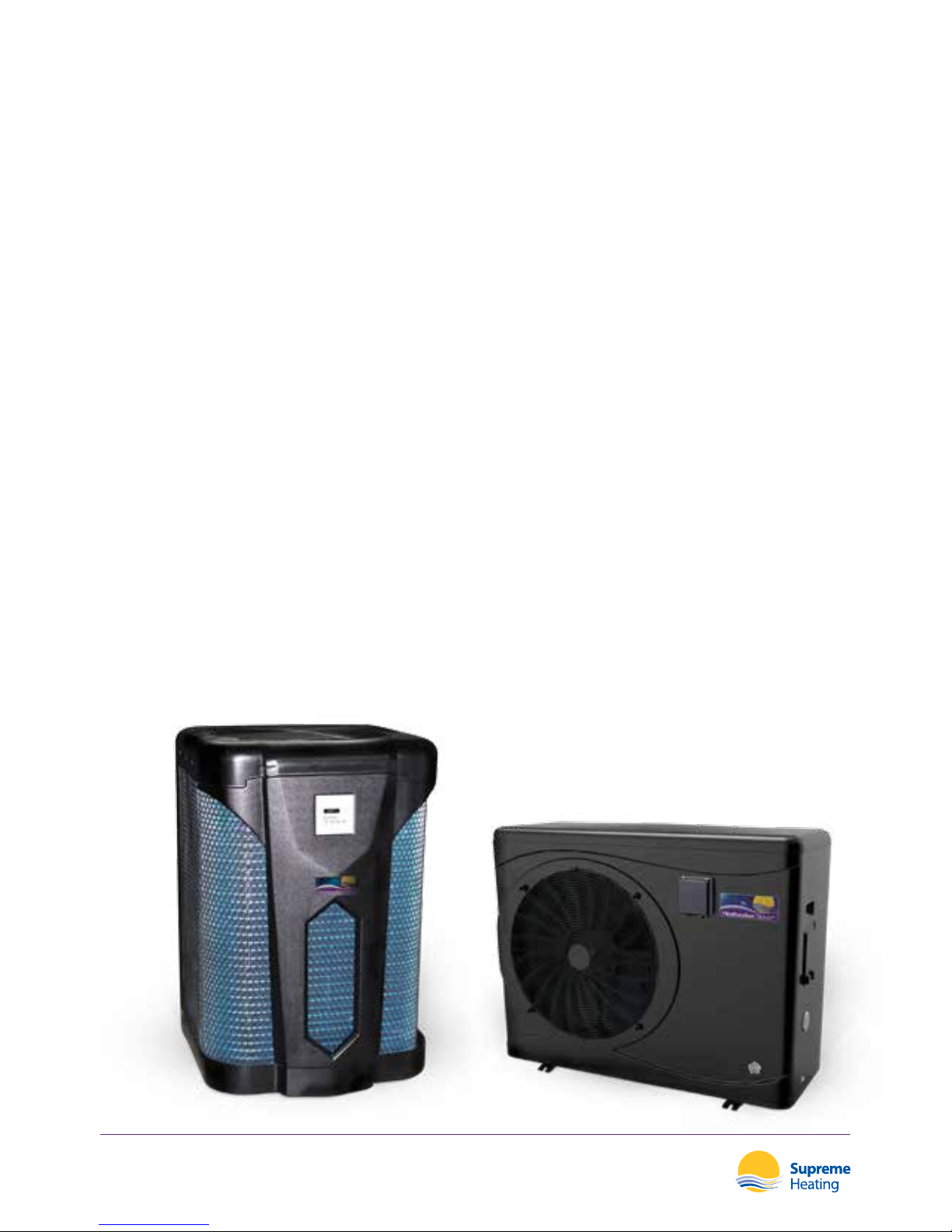
The national award winning Heatseeker Nova inverter heat pump is designed to heat
the pool by extracting heat from the outside air. The unique and innovative DC inverter
technology uses a variable-speed compressor which oers greater eciency and lowered
operating costs. The spiral titanium heat exchanger, combined with super-quiet operation
and soft start technology further enhances the eciency and lifespan of the Heatseeker
Nova heat pump.
The Heatseeker Nova+, the latest addition to Supreme Heating’s national award winning
Heatseeker Nova Series heat pumps, has arrived boasting even greater performance. The
Heatseeker Nova+ inverter heat pump oers the ability to dynamically vary the working
frequency of the inverter compressor. This, coupled with the synchronisation of the fan and
compressor speeds, optimises air ow to and from the heat pump. The enhanced technology of
the Nova+ provides up to 50% higher eciency with a COP of up to 13.6 compared to an on/o
type heat pump.
This manual provides installation and operation instructions for the Heatseeker Nova Series
Inverter Heat Pump. Read this manual carefully before proceeding with the installation and
operation of your heat pump. Consult your Heatseeker Nova distributor with any questions
regarding this equipment.
Installation and service must be performed by a qualied installer. The manufacturer will
not be responsible for any damage to the unit caused by improper installation, operation or
maintenance.
Page 5

Heatseeker Nova Series
Inverter Heat Pumps
03
Consumer and Safety Information
EARTHING
CONNECT THE GROUND WIRE BEFORE OPERATION
CIRCUIT BREAKER
USE AN EXCLUSIVE POWER SOURCE WITH A CIRCUIT
BREAKER
POWER SUPPLY
TURN OFF THE POWER SUPPLY BEFORE OPENING THE
CABINET WHEN PERFORMING MAINTENANCE
EXERCISE CAUTION
NEVER USE DAMAGED OR UNSPECIFIED ELECTRIC WIRES
KEEP CLEAR
DO NOT INSERT ANY OBJECTS INTO THE VENT OUTLET
DO NOT OBSTRUCT
DO NOT POUR WATER ON THE HEAT PUMP OR APPLY
PAINT OR INSECTICIDAL MATERIAL TO THE UNIT
WINTER COVER
PLACE THE WINTER COVER ON THE HEAT PUMP WHILE
THE UNIT IS UNUSED DURING WINTER
Page 6
GOLD AWARD
2015 NATIONAL
AWARDS OF
EXCELLENCE
Heatseeker Nova Series
Inverter Heat Pumps
04
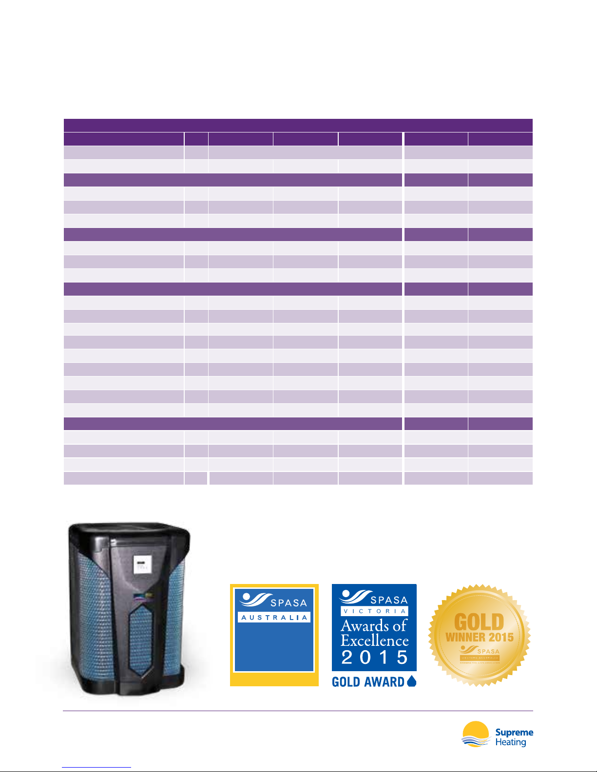
SPECIFICATIONS
MODEL 13 kW 17 kW 26 kW 35 kW 35 kW
- 3 PHASE
Discharge TOP SIDE
Fan Quantity 1 1 1 2 2
Performance at Air 27°C, Water 27°C
Heat Capacity (Min - Max) kW 6.8 - 13.0 7.9 - 17.1 12.0 - 26.0 8.0 - 35.0 8.0 - 35.0
Power Consumption kW 1.07 1.51 2.25 0.5 - 5.22 0.5 - 5.22
COP 7.6 7.6 8 6.7 - 16.0 6.7 - 16.0
Performance at Air 15°C, Water 27°C
Heat Capacity (Min - Max) kW 3.9 - 8.7 5.2 - 12.5 9.2 - 20.1 5.6 - 24.5 5.6 - 24.5
Power Consumption kW 1.07 1.51 2.25 0.68 - 4.8 0.68 - 4.8
COP 5.6 5.6 5.9 5.0 - 8.2 5.0 - 8.2
General
Rated Current
Amps
9.9 14.0 20.0 22.9 8.4
Minimum Fuse Current
Amps
15.0 20.0 32.0 32.0 13.0
Voltage/Power Supply
220-240v / 50Hz / 1PH 220-240v / 50Hz / 1PH 220-240v / 50Hz / 1PH 220-240v / 50Hz / 1PH 380-415v / 50Hz / 3PH
Pool Volume - Cold Climate Litres 30,000 40,000 60,000 80,000 80,000
Pool Volume - Warm Climate Litres 40,000 50,000 80,000 120,000 120,000
Advised Flow Rate L/m 150 165 200 240 240
Inlet / Outlet mm 50 50 50 50 50
Compressor Brand Hitachi Hitachi Panasonic Mitsubishi Mitsubishi
Noise Level (1m) db 56 59 62 42 - 60 42 - 60
Weight / Dimensions (L x W x H)
Net Weight kg 78 80 117 130 130
Gross Weight kg 85 90 129 148 148
Net Dimensions mm
690 * 740 * 955 690 * 740 * 955 750 * 800 * 1100 1076 * 470 * 1290 1076 * 470 * 1290
Packing Dimensions mm
745 * 830 * 1110 745 * 830 * 1110 800 * 890 * 1250 1156 * 517 * 1435 1156 * 517 * 1435
Technical Specications
Heatseeker Nova Inverter Heat Pump
Page 7
C
A
B
Heatseeker Nova Series
Inverter Heat Pumps
05
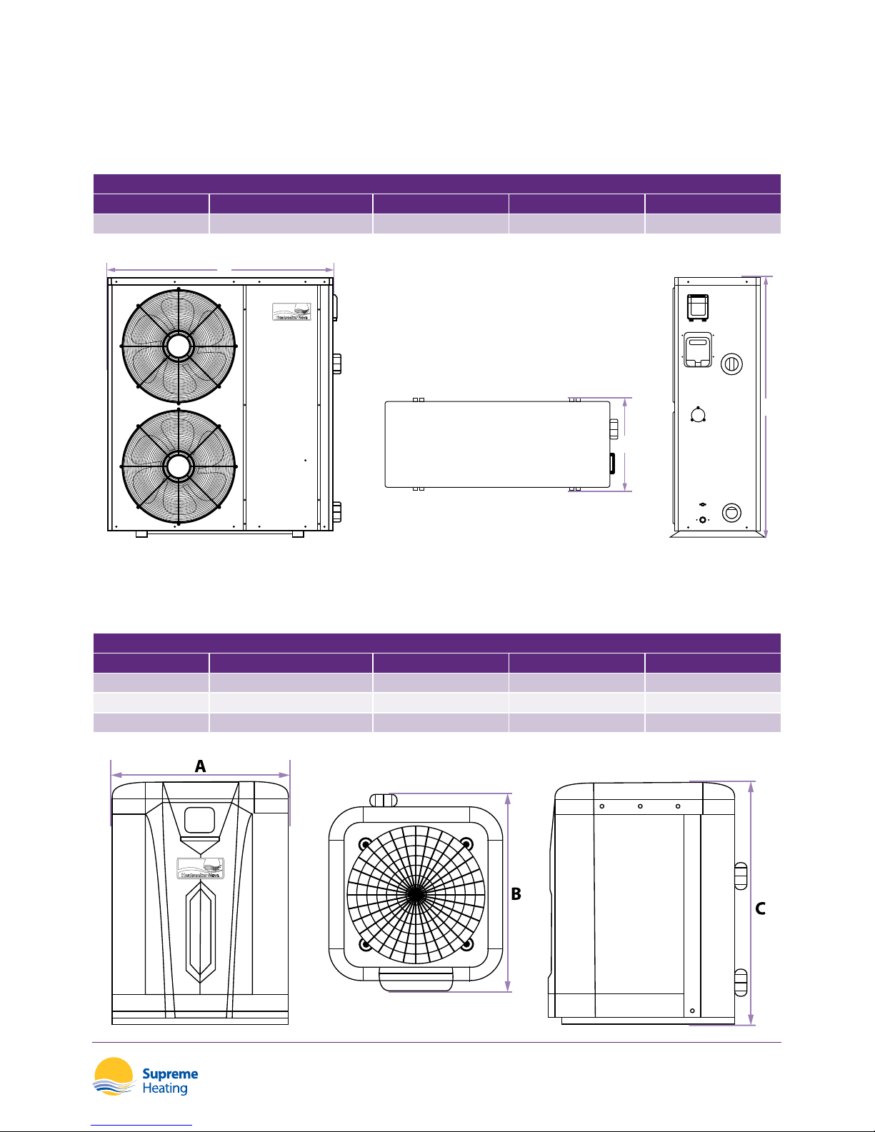
Dimensions
Heatseeker Nova Inverter Heat Pump
SIDE DISCHARGE DIMENSIONS
MODEL CODE A Length (mm) B Depth (mm) C Height (mm)
35kW SHEATPUMP35CSI 1076 470 1290
TOP DISCHARGE DIMENSIONS
MODEL CODE A Length (mm) B Depth (mm) C Height (mm)
13kW SHEATPUMPDCVI13 690 740 955
17kW SHEATPUMPDCVI17 690 740 955
26kW SHEATPUMPDCVI26 750 800 1100
Page 8
Heatseeker Nova Series
Inverter Heat Pumps
06
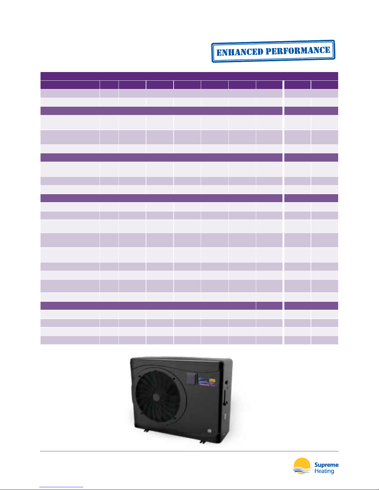
SPECIFICATIONS
MODEL C20 C30 C40 C50 C60 C80 C60T C80T
Discharge SIDE SIDE
Fan 1 1 1 1 2 2 2 2
Performance at Air 27°C, Water 26°C
Heat Capacity
(Min - Max)
kW 2.3 - 9.2 2.9 - 12.5 3.8 - 16.0 4.7 - 19.0 5.9 - 24.0 6.8 - 28.5 5.9 - 24.0 6.8 - 28.5
Power Consumption
(Min - Max)
kW 0.18 - 1.59 0.22 - 2.02 0.3 - 2.66 0.37 - 3.4 0.47 - 4.28 0.54 - 5.09 0.47 - 4.28 0.54 - 5.09
COP 5.8 - 13.0 6.2 - 13.0 6.0 - 12.6 5.6 - 12.5 5.6 - 12.5 5.6 - 12.4 5.6 - 12.5 5.6 - 12.4
Performance at Air 15°C, Water 26°C
Heat Capacity
(Min - Max)
kW 1.9 - 6.8 2.2 - 9.2 3.0 - 11.5 3.9 - 14.7 4.7 - 18.9 5.6 - 23.2 4.7 - 18.9 5.6 - 23.2
Power Consumption kW 0.27 - 1.51 0.31 - 2.0 0.39 - 2.55 0.51 - 3.27 0.61 - 4.2 0.73 - 5.16 0.61 - 4.2 0.73 - 5.16
COP 4.5 - 7.1 4.6 - 7.1 4.5 - 7.0 4.5 - 7.0 4.5 - 7.0 4.5 - 7.0 4.5 - 7.0 4.5 - 7.0
General
Rated Current Amps 6.9 8.5 11.7 16.3 18.9 22.5 6.9 8.2
Minimum Fuse Current Amps 10.0 15.0 20.0 20.0 32.0 32.0 9.0 13.0
Voltage/Power Supply
220-240v /
50Hz / 1PH
220-240v /
50Hz / 1PH
220-240v /
50Hz / 1PH
220-240v /
50Hz / 1PH
220-240v /
50Hz / 1PH
220-240v /
50Hz / 1PH
380-415v /
50Hz / 3PH
380-415v /
50Hz / 3PH
Pool Volume
Cold Climate
Litres 20,000 30,000 40,000 50,000 60,000 80,000 60,000 80,000
Pool Volume
Warm Climate
Litres 30,000 40,000 50,000 60,000 70,000 90,000 70,000 90,000
Advised Flow Rate L/m 50 70 80 100 140 180 140 180
Inlet / Outlet mm 50 50 50 50 50 50 50 50
Compressor Brand
GMCC /
Toshiba
GMCC /
Toshiba
Mitsubishi Mitsubishi Mitsubishi Mitsubishi Mitsubishi Mitsubishi
Noise Level (1m) db 40 - 52 40 - 52 41 - 54 41 - 54 42 - 60 42 - 60 42 - 60 42 - 60
Weight / Dimensions (L x W x H)
Net Weight kg 49 59 67 87 123 127 123 127
Gross Weight kg 57 69 76 97 135 140 135 140
Net Dimensions mm
1025 * 395 * 565 1068 * 465 * 715 1068 * 465 * 715 1145 * 480 * 886 1076 * 470 * 1290 1076 * 470 * 1290 1076 * 470 * 1290 1076 * 470 * 1290
Packing Dimensions mm
1080 * 405 * 705 1120 * 495 * 855 1120 * 495 * 855 1200 * 515 * 1015 1156 * 517 * 1430 1156 * 517 * 1430 1156 * 517 * 1430 1156 * 517 * 1430
Technical Specications
Heatseeker Nova+ Inverter Heat Pump
Page 9
A
C
B
Heatseeker Nova Series
Inverter Heat Pumps
07
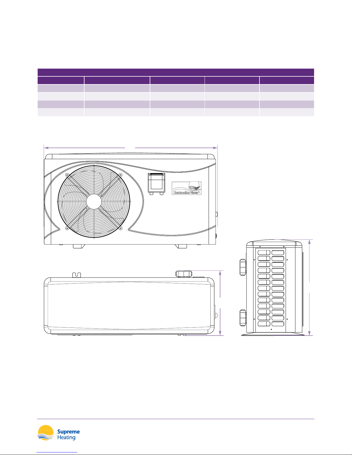
Dimensions
Heatseeker Nova+ Inverter Heat Pump
TOP DISCHARGE DIMENSIONS
MODEL CODE A Length (mm) B Depth (mm) C Height (mm)
C20 SNOVAPLUSC20 1025 395 565
C30 SNOVAPLUSC30 1068 465 715
C40 SNOVAPLUSC40 1068 465 715
C50 SNOVAPLUSC50 1145 480 886
Page 10
A
C
B
Heatseeker Nova Series
Inverter Heat Pumps
08
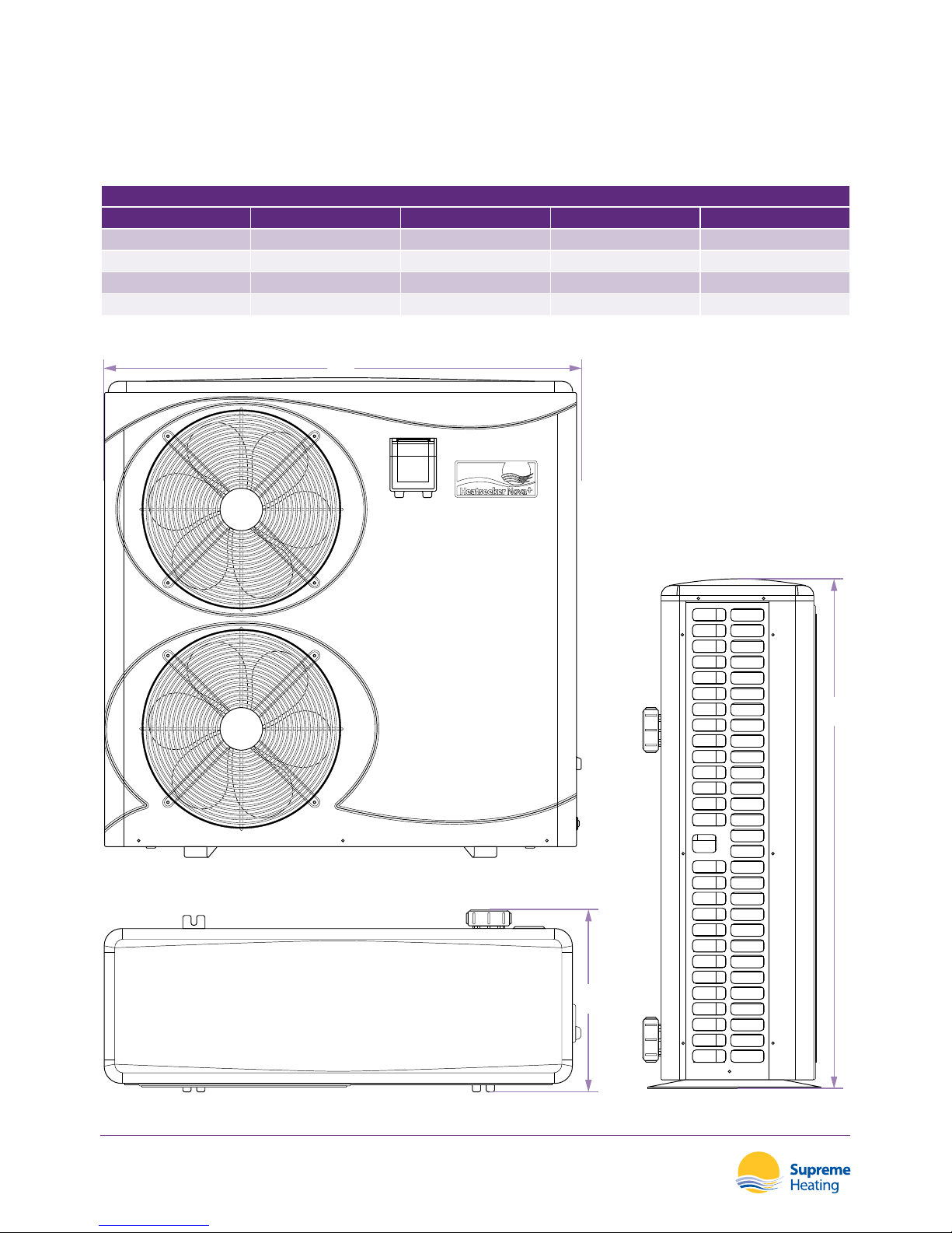
Dimensions
Heatseeker Nova+ Inverter Heat Pump
TOP DISCHARGE DIMENSIONS
MODEL CODE A Length (mm) B Depth (mm) C Height (mm)
C60 SNOVAPLUSC60 1076 470 1290
C80 SNOVAPLUSC80 1076 470 1290
C60T (three phase) SNOVAPLUSC60T 1076 470 1290
C80T (three phase) SNOVAPLUSC80T 1076 470 1290
Page 11

Heatseeker Nova Series
Inverter Heat Pumps
09
Installation and Connection
Installation Safety Notes
The manufacturer supplies the heat pump only. All other components, including a bypass,
must be provided by the installer or user.
ATTENTION
The following instructions must be followed when installing the heat pump.
1. Sanitation and automatic dosing systems must be plumbed after the heat pump. A check
valve must be installed between the sanitation/automatic dosing system and the heat pump
to prevent chemicals returning to the heat pump.
2. A bypass must be installed for the use of heat pumps.
3. Always place the heat pump on a solid foundation and use the included rubber mounts to
avoid vibration and noise.
4. Always hold the heat pump upright. If the unit has been held at an angle, wait at least 24
hours before starting the heat pump.
5. For optimum performance the ow rate must match specications provided by the manufacturer.
6. For indoor installation, please consult your installer.
7. In areas subject to sub zero temperatures, the heat pump must be de-commissioned during
the winter months. To do this, the drainage plug must be removed from the heat pump to
allow water to drain from the heat exchanger. Once the water has been drained from the unit,
the drainage plug can be re-installed for use of the heat pump.
Heat Pump Location
For optimum performance ensure good ventilation, stable and reliable power supply and ensure
swimming pool lters are present.
The unit may be installed in virtually any outdoor location as long as the specied minimum
clearances to other objects are maintained (as per the following diagram).
ATTENTION
Never install the unit in a closed room with limited air volume in which the air
expelled from the unit will be re-used, or close to shrubbery that could block
the inlet. Such locations impair the continuous supply of fresh air, resulting in
reduced eciency and possible prevention of sucient heat output, which
will void the compressor warranty.
See drawing on the following page for minimum clearance dimensions.
Page 12
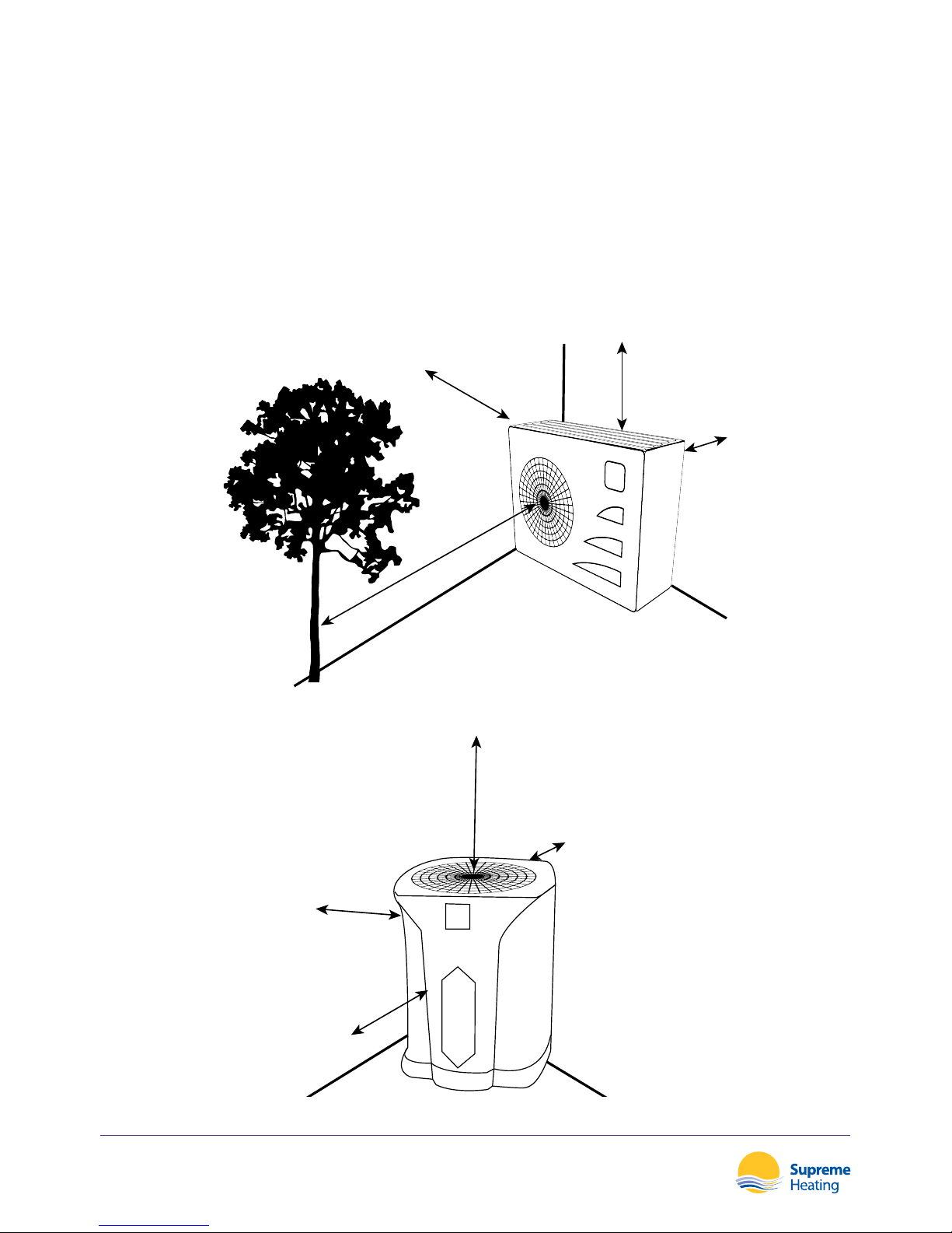
2500mm
From Front
Discharge
800mm
From Sides
400mm
From Back
500mm
From Top
2000mm
From Top
Discharge
800mm
From Sides
1000mm
From Back
800mm
From Front
Heatseeker Nova Series
Inverter Heat Pumps
10
Distance from your swimming pool
The heat pump is usually installed within a perimeter area extending 7.5m from the swimming
pool. The greater the distance from the pool, the greater the heat loss in the pipes. As the pipes
are mostly underground, the heat loss is low for distances up to 30m (15m from and to the
pump; 30m in total) unless the ground is wet or the groundwater level is high. A rough estimate
of the heat loss per 30m is 0.6 kWh (2,000 BTU) for every 5°C dierence between the water
temperature in the pool and the temperature of the soil surrounding the pipe. This increases the
operating time by 3% to 5%.
Side Discharge
Top Discharge
Page 13
Heatseeker Nova Series
Inverter Heat Pumps
11
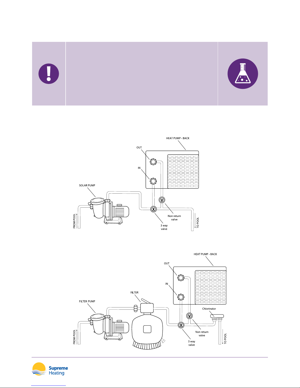
Check Valve Installation
AUTOMATIC DOSING
Sanitation and automatic dosing systems must be
plumbed after the heat pump. A check valve must be
installed between the sanitation/automatic dosing system
and the heat pump to prevent chemicals returning to the
heat pump. Failure to observe this instruction will void the
warranty.
Typical Arrangement
Independent System
In-line System
Page 14
A
B
Heatseeker Nova Series
Inverter Heat Pumps
12
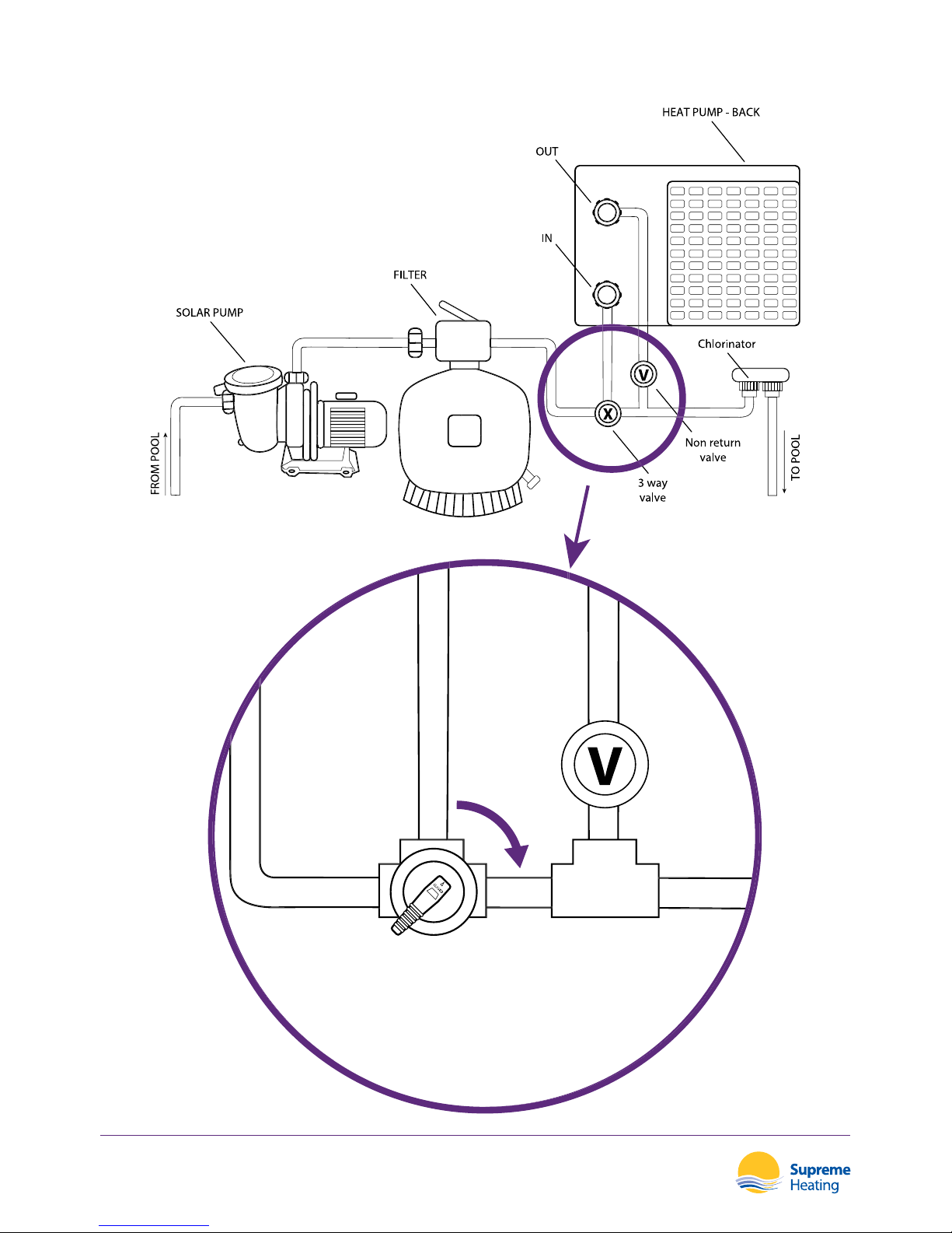
Adjusting the Bypass
Page 15

Heatseeker Nova Series
Inverter Heat Pumps
13
Use the following procedure to adjust the bypass:
1. Close the valve to Position A
2. Turn on the circulation pump
3. Slowly open the valve towards Position B until the display message of “ON” or error code
of “EE03” disappears.
Once the message clears, the default display is the current water temperature. Starting
sequence will now begin.
Optimal operation and water ow through the heat pump occurs when the cooling gas pressure
is 22 ±2 bar.
This pressure can be read on the pressure gauge next to the heat pump control panel.
BYPASS INSTALLATION
Operation without a bypass or with improper bypass
adjustment may result in suboptimal heat pump operation
and possible damage to the heat pump. Failure to observe
this instruction will void the warranty.
Electrical Connection
EARTHING
Although the heat pump is electrically isolated from the
rest of the swimming pool system, this only prevents
the ow of electrical current to/from the water in the
pool. Earthing is still required for protection against short
circuits inside the unit.
Before connecting the unit, verify that the supply voltage matches the operating voltage of the
heat pump. It is recommended to connect the heat pump to a circuit with its own fuse or circuit
breaker (slow type; curve D) and to use adequate wiring.
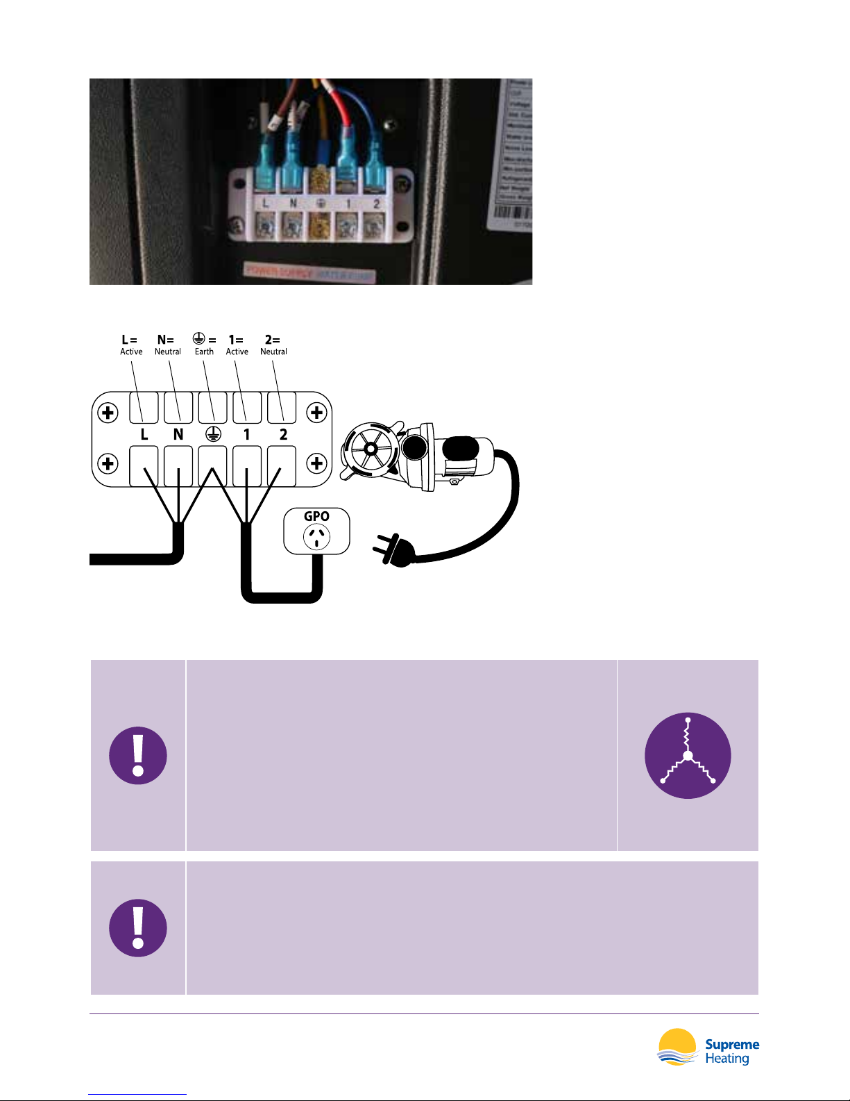
Connect the electrical wires to the terminal block marked ’POWER SUPPLY’ . A second terminal
block marked ‘WATER PUMP’ is located next to the rst one. The lter pump (max. 5 Amps/240V)
can be connected to the second terminal block. This allows the lter pump operation to be
controlled by the heat pump.
Page 16
Heatseeker Nova Series
Inverter Heat Pumps
14
THREE PHASE MODELS
In the case of three phase models, swapping two phases
may cause the electric motors to run in the reverse
direction, which can cause damage. As a preventative
measure, the unit has a built-in protective device that
breaks the circuit if the connection is incorrect. If the red
led above this safety device lights up, the connections of
the two phase wires must be swapped.
ATTENTION
A disconnect means (circuit breaker, fused or un-fused switch) should be
located within sight of and readily accessible from the unit.
This prevents remotely-energizing unattended equipment and permits
turning o power at the unit while the unit is being serviced.
Cable Wiring
Connect the power supply wire within the electric box.
Page 17

Heatseeker Nova Series
Inverter Heat Pumps
15
Initial Operation
ATTENTION
In order to heat the water in the pool (or spa), the lter pump must be running
for water to circulate through the heat pump. The heat pump will not start if
the water is not circulating.
After all connections have been made and checked, carry out following procedure:
1. Switch on the lter pump. Check for leaks and verify that water is owing to and from the
swimming pool.
2. Connect power to the heat pump and press the On/O Button on the automatic control
panel. The unit will start up after the time delay expires.
3. After a few minutes, check whether the air blowing out of the unit is cooler.
4. When the lter pump is turned o the unit should also turn o automatically. If this does not
occur, adjust the Water Flow Switch (detailed below).
5. Allow the heat pump and the lter pump to run 24 hours a day until the desired water
temperature is reached. Once the desired temperature is reached, the heat pump will stop
running. When the swimming pool water drops 2°C below the set temperature, the heat
pump will restart automatically.
Dependant on the initial temperature of the swimming pool water and the air temperature, it
may take several days for the water to heat to the desired temperature.
A Supreme Heating Heatseeker Diamond pool cover & roller system can dramatically reduce the
required heat up time and is strongly recommended.
Water Flow Switch
The heat pump is equipped with a ow switch to ensure the unit is operating with an adequate
water ow rate. The ow switch will detect ow through the heat exchanger and allow the
heat pump to continue running. If the water ow is interrupted or stopped, the ow switch will
trigger the heat pump to turn o.
Time Delay
The heat pump has a built-in 3 minute start up delay to protect the circuitry and avoid
excessive contact wear. The unit will restart automatically after this time delay expires. If a brief
power interruption occurs this will trigger the time delay and prevent the unit from restarting
immediately.
Page 18

Heatseeker Nova Series
Inverter Heat Pumps
16
Condensation
The air drawn into the heat pump is cooled by the operation of the heat pump for heating
the pool water, which may cause condensation on the ns of the evaporator. The amount
of condensation may be as much as several litres per hour at high relative humidity. This is
sometimes mistaken as a water leak.
Pressure Gauge Display (R410A)
Examine the pressure gauge which indicates the refrigerant gas pressure of the unit. The below
table shows the gas pressure (R410A) value when the heat pump power is o and running.
Unit Condition Power O
Ambient °C -5~5 5~15 15~25 25~35
Water temp °C / / / /
Pressure gauge Mpa 0.68~0.93 0.93~1.25 1.25~1.64 1.64~2.1
Unit Condition Running
Ambient °C / / / / /
Water temp °C 10~15 15~20 20~25 25~30 30~35
Pressure gauge Mpa 1.3~1.8 1.5~1.9 1.6~2.3 1.9~2.8 2.1~3.5
Page 19
Heatseeker Nova Series
Inverter Heat Pumps
17
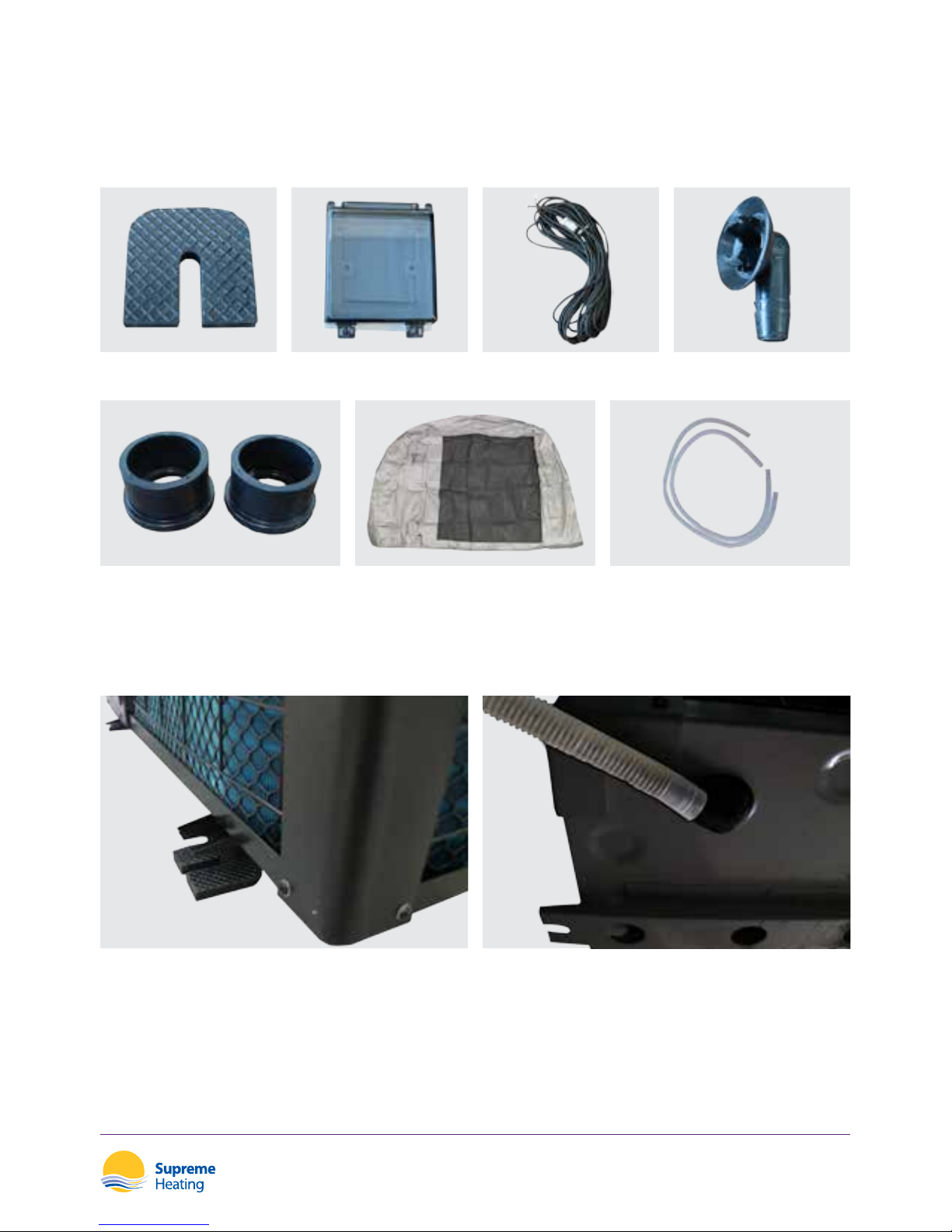
1. Place one anti-vibration base under each
corner of the heat pump.
1. Install the drainage point under the
bottom of the heat pump.
2. Connect with the drainage hose to drain
out the water.
Accessories
Accessories List
2 x Water Connection Assembly
4 x Anti-vibration Base 1 x Controller Cover 1 x Extension Cable 2 x Draining Jet
1 x Winter Cover 1 x Drainage Hose
Installation of Accessories
Anti-vibration bases Drainage Point (side discharge only)
Page 20
Heatseeker Nova Series
Inverter Heat Pumps
18
Operation
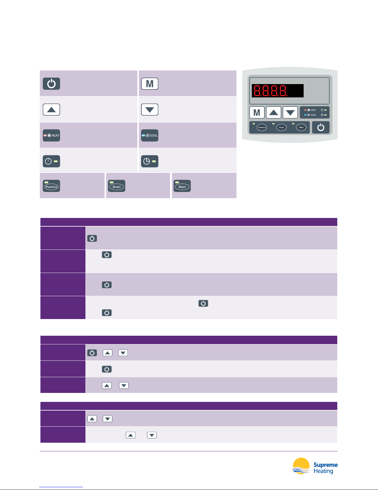
Controller Overview
POWER MODE / SETTINGS
UP DOWN
HEAT MODE
When in operation the light
will be on. When defrosting the
light will ash.
COOL MODE
When in operation the light
will be on.
AUTOMATIC STOP
When in operation the light
will be on.
AUTOMATIC START
When in operation the light
will be on.
POWERFUL
When in
operation the
light will be on.
SMART
When in
operation the
light will be on.
SILENT
When in
operation the
light will be on.
Power (On / O)
TURNING YOUR HEAT PUMP ON/OFF
OVERVIEW
STEP 1
Press
to start the heat pump.
The LED display will show the desired water temperature for 5 seconds, followed by the inlet water
temperature and the operation mode.
STEP 2
Press
to stop the heat pump. The LED display will show “OFF”.
NOTE
During parameter checking and setting: Press
to quick exit and save the current setting.
Press
again to turn on/o the heat pump.
Mode Controls
ADJUSTING THE HEAT OR COOL MODE
OVERVIEW
+ +
STEP 1
Press
for 5 seconds.
STEP 2
Press
or to adjust the “Heat MODE” or “Cool MODE”.
LOCK / UNLOCK THE DISPLAY
OVERVIEW
+
STEP 1
Press and hold
and for 5 seconds to lock/unlock the display
Page 21
Heatseeker Nova Series
Inverter Heat Pumps
19
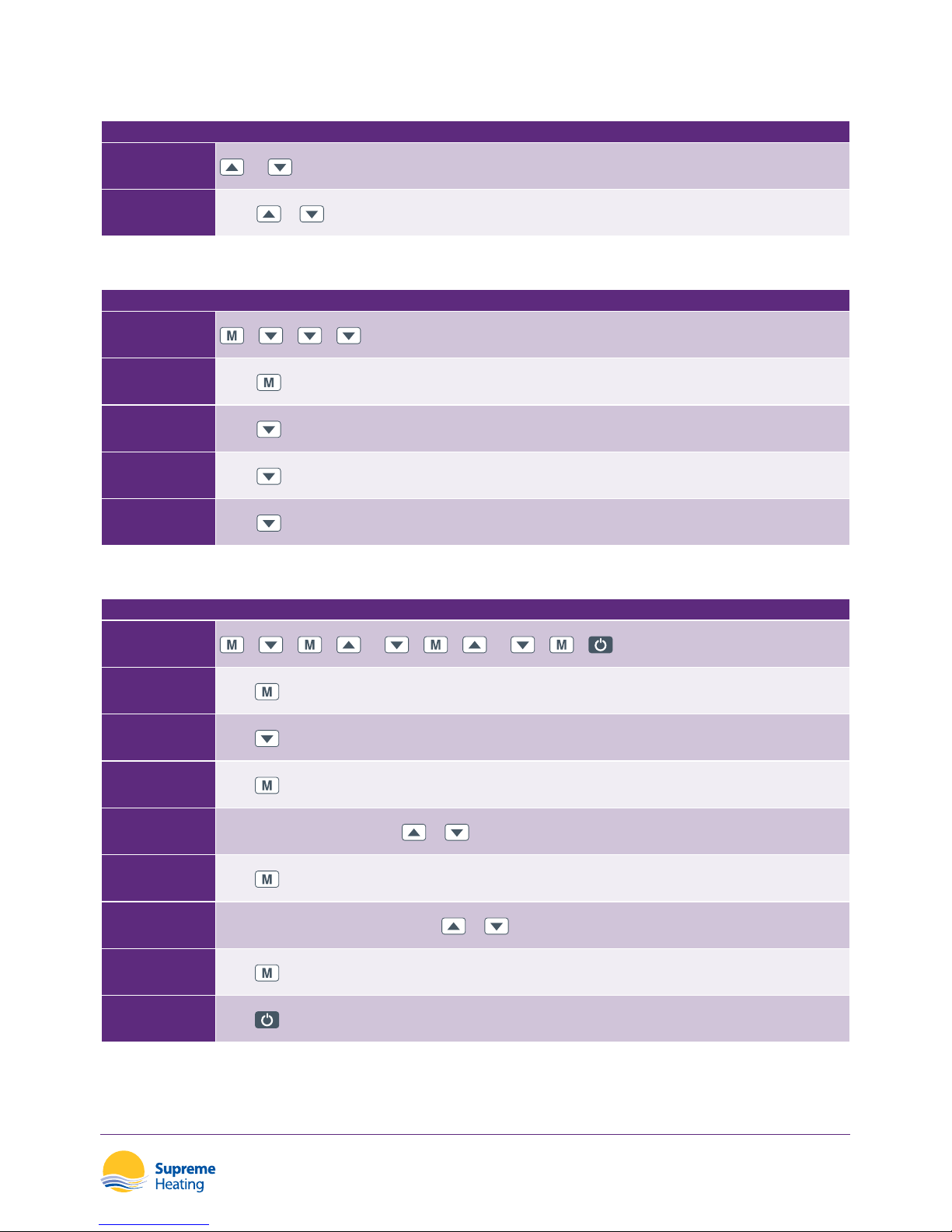
Water Temperature Settings
ADJUSTING THE WATER TEMPERATURE DIRECTLY
OVERVIEW
OR
STEP 1
Press
or to adjust the water temperature.
Checking the Time
CHECK THE CURRENT TIME SETTINGS
OVERVIEW
+ + +
STEP 1
Press
STEP 2
Press
to check the “Current Time”.
STEP 3
Press
a second time to check the “Automatic Start Time”.
STEP 4
Press
a third time to check the “Automatic Stop Time”.
Setting the Time
SETTING THE TIME
OVERVIEW
+ + + OR + + OR + +
STEP 1
Press
STEP 2
Press
to view the “Current Time” Display.
STEP 3
Press
to enter the “Hour” setting.
STEP 4
The “Hour” will ash, then press
or to set the hour.
STEP 5
Press
to save the “Hour”.
STEP 6
The “Minute” will now ash, then press
or to set the minute.
STEP 7
Press
to save the current time setting.
STEP 8
Press
for quick exit and saving.
Page 22
Heatseeker Nova Series
Inverter Heat Pumps
20
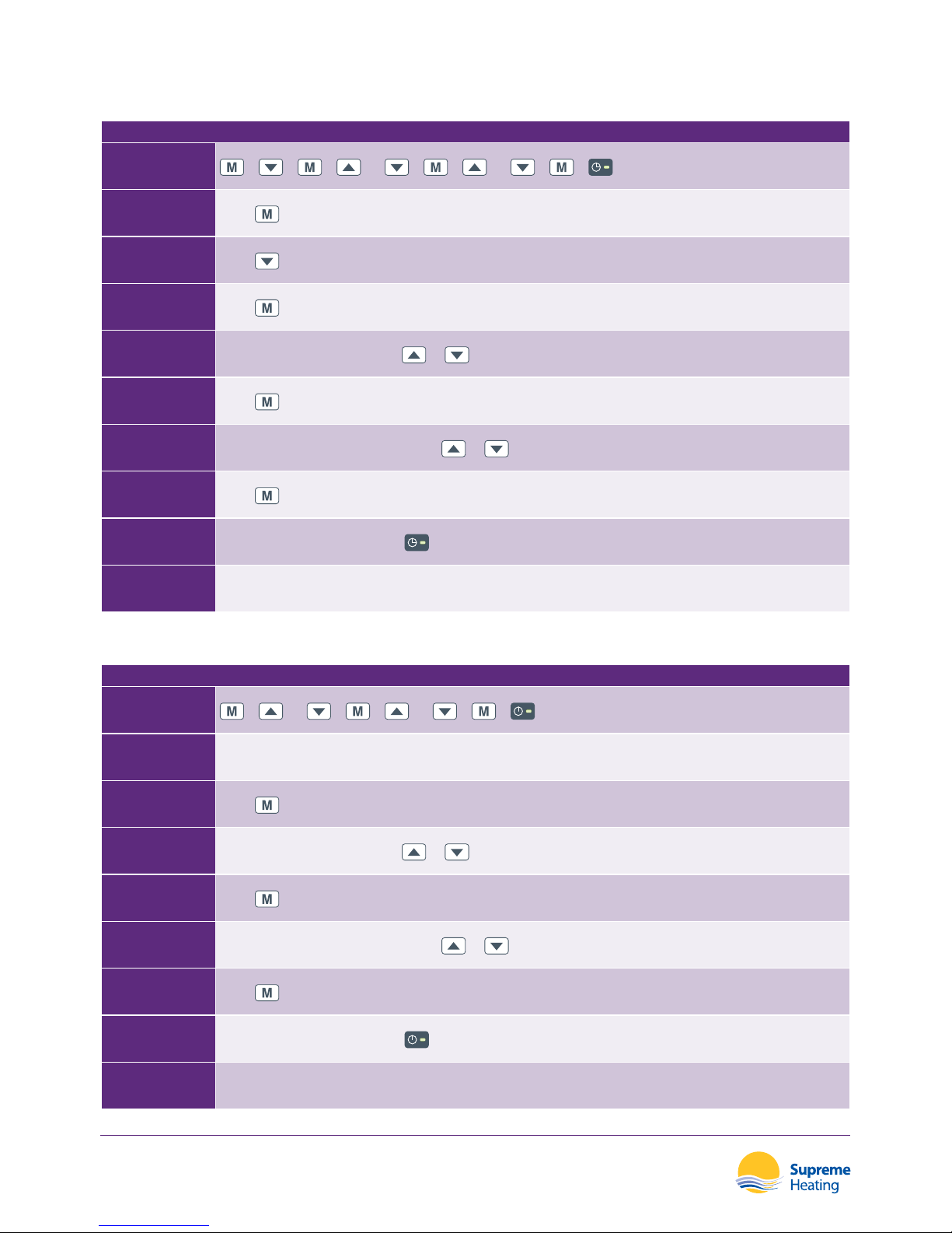
Setting the Automatic Start Time
SETTING THE AUTOMATIC START TIME
OVERVIEW
+ + + OR + + OR +
=
STEP 1
Press
STEP 2
Press
twice to reach the “Automatic Start Time” menu.
STEP 3
Press
to enter the menu.
STEP 4
The “Hour” will ash, then press
or to set the hour.
STEP 5
Press
to save the “Hour”.
STEP 6
The “Minute” will now ash, then press
or to set the minute.
STEP 7
Press
to save the current time setting.
STEP 8
If the time is successfully set, the
light will display.
STEP 9 If you wish to cancel the automatic start setting, set the time as 00.00
Setting the Automatic Stop Time
SETTING THE AUTOMATIC START TIME
OVERVIEW
+ OR + + OR +
=
STEP 1 Once the Automatic Start Time is saved, the screen will enter into the “Automatic Stop Time” interface.
STEP 2
Press
to enter the menu.
STEP 3
The “Hour” will ash, then press
or to set the hour.
STEP 4
Press
to save the “Hour”.
STEP 5
The “Minute” will now ash, then press
or to set the minute.
STEP 6
Press
to save the current time setting.
STEP 7
If the time is successfully set, the
light will display.
STEP 8 If you wish to cancel the automatic stop setting, set the time as 00.00
Page 23
Heatseeker Nova Series
Inverter Heat Pumps
21
ATTENTION
Failure to correctly set the automatic stop time will allow the pump to run in
the current mode for 24 hours, or until set temperature is reached.
ATTENTION
After setting the automatic start and stop time, if the current time is in the range
of time o, the heat pump will turn o automatically upon exiting the menu.
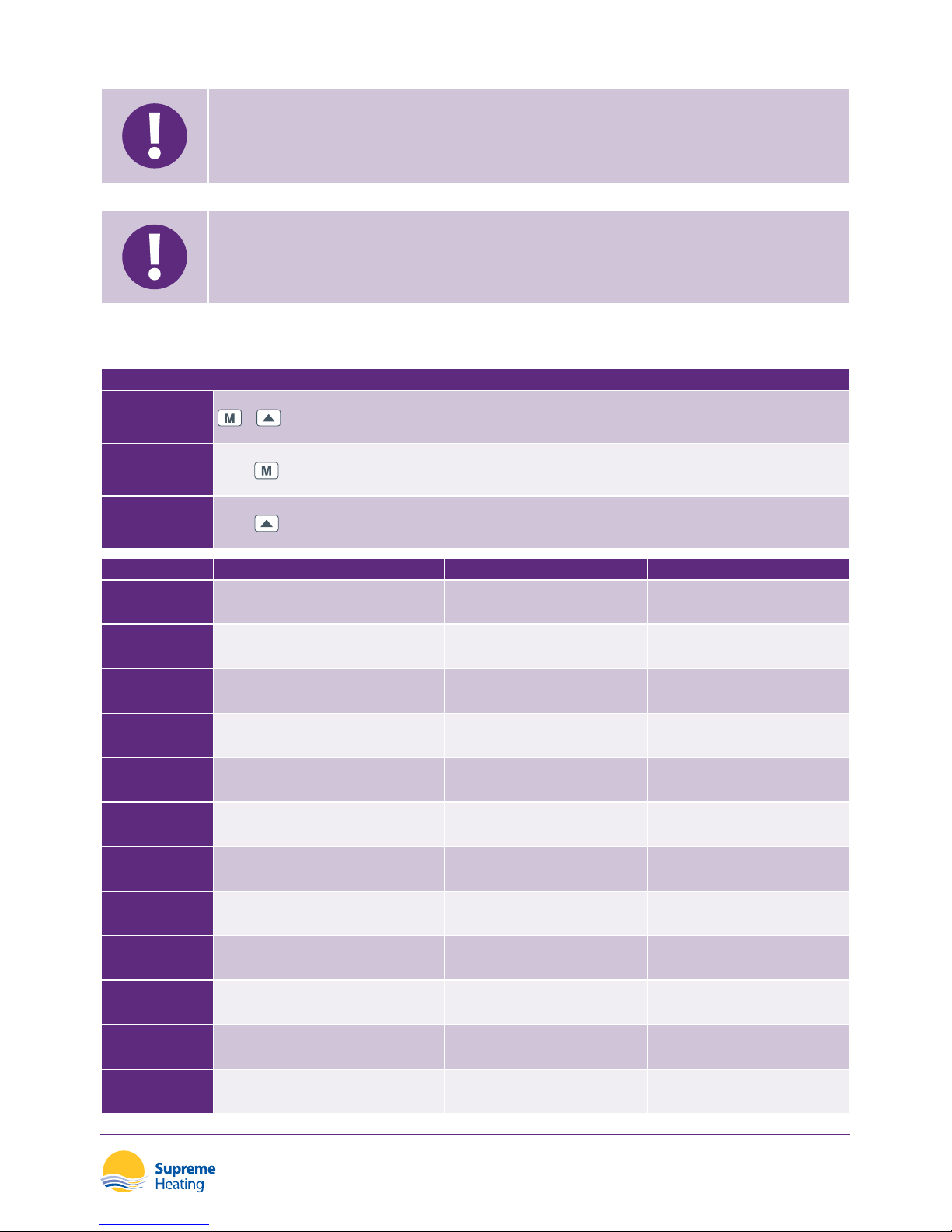
Checking the Parameters
PARAMETERS
OVERVIEW
+
STEP 1
Press
STEP 2
Press
to check the user parameter from d0 to d11.
PARAMETERS CONDITION RANGE REMARKS
d0 IPM mould temperature 0-120°C Real testing value
d1 Inlet water temperature -9-99°C Real testing value
d2 Outlet water temperature -9-99°C Real testing value
d3 Ambient temperature (-30°C)-70°C Real testing value
d4 Gas return temperature (-30°C)-70°C Real testing value
d5 Coil temperature (-30°C)-70°C Real testing value
d6 Gas exhaust temperature 0-C5°C(125°C) Real testing value
d7 Steps of electronic expansion valve 0-99 N*5
d8 Compressor operating frequency 0-99Hz Real testing value
d9 Compressor current 0-30A Real testing value
d10 Current fan speed 0-1200(RPM) Real testing value
d11 Error code for last time All error code
Page 24

Heatseeker Nova Series
Inverter Heat Pumps
22
PARAMETERS
OVERVIEW
+
STEP 1
Press
STEP 2
Press
to check/adjust the user parameter from P1 to P7.
PARAMETERS CONDITION RANGE DEFAULT REMARKS
P1 Working mode 0-1 1 1 Heating mode, 0 Cooling mode
P2 Timer on/o 0-1 0
1 Timer on/o is under function,
0 Timer on/o is out of function (The
setting of P4 and P5 won’t work)
P3 Water pump 0-1 0
1 Always running, 0 Depends on the
running of compressor
P4 Current time HH:MM 00:00
0-23:0-59
P5 Timer on HH:MM 00:00
0-23:0-59
P6 Timer o HH:MM 00:00
0-23:0-59
P7 Inlet water temp. correction -9~99 0 Default setting: 0
Page 25

Heatseeker Nova Series
Inverter Heat Pumps
23
Heat Pump Modes
Powerful Mode
OPERATING IN POWERFUL MODE
OVERVIEW
STEP 1
Press
and the light will ash. The heat pump will operate in ‘Full output’ only.
Smart Mode
OPERATING IN SMART MODE
OVERVIEW
STEP 1
Press
and the heat pump will operate in ‘Medium output’ and ‘Full output’.
When operating in ‘Medium output’, the light beside Smart will ash.
When in ‘Full output’, the light beside Smart will turn on and the light beside Powerful will ash.
Silent Mode
OPERATING IN SILENT MODE
OVERVIEW
STEP 1
Press
and the heat pump will operate in ‘Medium output’ and ‘Small output’.
When in ‘Small output’, the light beside Silent will ash.
When in ‘Medium output’, the light beside Silent will turn on and the light beside Smart will ash.
Notes
1. When the Heatseeker Nova heat pump stops running for 30 seconds, the water pump will
shut o automatically (in the case of an independent system).
2. The LED controller can operate the water pump by connecting an additional cable between
the pump and the “PUMP” terminal on the heat pump.
3. It is necessary to put an extra 3-phase transfer device for a 3-phase water pump.
System Reset Function
SYSTEM RESET FUNCTION
OVERVIEW
+
STEP 1
Press and hold
+ together for 10 seconds
STEP 2 The system will reset and display “0000” on the controller.
Page 26

Heatseeker Nova Series
Inverter Heat Pumps
24
Troubleshooting - Heatseeker Nova
Error Code Displayed on LED Controller
MALFUNCTIONS ERROR REASONS SOLUTIONS
Inlet water temperature sensor
failure
PP01
The sensor has an open or short
circuit
Check or change the sensor
Outlet water temperature
sensor failure
PP02
The sensor has an open or short
circuit
Check or change the sensor
Heating condenser sensor failure PP03
The sensor has an open or short
circuit
Check or change the sensor
Gas return sensor failure PP04
The sensor has an open or short
circuit
Check or change the sensor
Ambient temperature
sensor failure
PP05
The sensor has an open or short
circuit
Check or change the sensor
Condenser gas exit
failure
PP06
The sensor has an open or short
circuit
Check or change the sensor
Antifreeze protection in winter PP07
Ambient temperature or water
inlet temperature is too low
Low ambient
temperature protection
PP08
Ambient temperature or water
inlet temperature is too low
High pressure failure EE01
1. Too much refrigerant
2. Insucient air ow
1. Discharge redundant refrigerant
from heat pump gas system
2. Clean the air exchange
Low pressure failure EE02
1. Insucient refrigerant
2. Insucient water ow
3. Filter or capillary jammed
1. Check for gas leakage, re-ll the
refrigerant
2. Clean the air exchanger
3. Replace the lter or capillary
Water ow failure
EE03 or
“ON”
Low water ow, wrong ow
direction, or ow switch failure
Check if the water ow is high
enough and ow is in the correct
direction. Or the ow switch may
have failed.
The water is overheating EE04 Water ow low or no water
1. Repair the circulating pump
2. Clean the water pipe
3. Check the water switch
Page 27

Heatseeker Nova Series
Inverter Heat Pumps
25
MALFUNCTIONS ERROR REASONS SOLUTIONS
Gas exhaust temperature sensor
failure
EE05
1. Insucient gas
2. The throttling device is jammed
3. Low water ow
1. Change the throttling device
2. Check the water pump
Controller failure EE06
1. Wire connection is not correct
2. Controller failure
1. Check or change the signal wire
2. Restart the power supply or
change the controller
Converter failure EE07 Converter board failure
Restart the power or change the
converter board
Communication failure between
controller and converter board
EE08
1. Insucient wire connection
2. Controller failure
1. Check the wire connection.
2. Restart the power supply
3. Change the controller.
Communication failure between
converter and outdoor board
EE09
Wire connection between
communication wire and outdoor
board is incorrect.
Restart the power supply or
change the outdoor board.
Module board failure between
outdoor board and module board
EE10
1. Communication wire is broken.
2. Outdoor board or module board
failure.
Restart the power or change the
broken board.
Module board failure EE11
Data is incorrect or module board
failure.
Restart the power or change the
broken board.
Direct main current’s voltage too
high or too low protection
EE12
1. The pressure is too high or too
low.
2. The inner communication
contactor is broken.
1. Check the power supply
2. Change the contactor
Over current protection EE13
1. Electric supply pressure is too
low.
2. The Heat Pump is overloaded.
1. Check the power supply
2. Check whether the water
temperature is too high.
The heating light is on
Defrosting
Page 28

Heatseeker Nova Series
Inverter Heat Pumps
26
Troubleshooting - Heatseeker Nova
+
Error Code Displayed on LED Controller
MALFUNCTIONS ERROR REASONS SOLUTIONS
Inlet water temperature sensor
failure
PP01
The sensor has an open or short
circuit
Check or change the sensor
Outlet water temperature sensor
failure
PP02
The sensor has an open or short
circuit
Check or change the sensor
Condenser sensor failure PP03
The sensor has an open or short
circuit
Check or change the sensor
Gas return sensor failure PP04
The sensor has an open or short
circuit
Check or change the sensor
Ambient temperature sensor failure PP05
The sensor has an open or short
circuit
Check or change the sensor
Gas exhaust sensor failure PP06
The sensor has an open or short
circuit
Check or change the sensor
Antifreeze protection in winter PP07
Ambient temperature or
water inlet temperature is
too low
1. The rst grade antifreeze
protection condition: when
6°C<T1 water in temperature
<10°C and T5 ambient
temperature
3°C, water pump
should operate 30 minutes, then
stop 30 minutes in this cycle.
When ambient temperature
T5>5°C or T1 water in
temperature
15°C, water pump
stop operating will activate the
antifreeze protection.
2. The second grade antifreeze
protection condition; T1 water in
temperature
6°C and T5 2°C, it
goes into the second antifreeze
protection, the heat pump
should go into Smart mode for
water heating will to T1>15°C or
T5>7°C.
Remarks: The water pump and heat
pump must be turned ON or in
standby status.
Page 29

Heatseeker Nova Series
Inverter Heat Pumps
27
MALFUNCTIONS ERROR REASONS SOLUTIONS
Low ambient temperature
protection
PP08
Ambient temperature or water
inlet temperature is too low
Cooling pipe temperature too high
protection
PP10 Check the system
High pressure failure EE01
1. Too much refrigerant
2. Ambient temperature or water
temperature is too high
3. Operating frequency is too high
4. Fan motor failure
5. High pressure valve failure
1. Discharge redundant refrigerant
2. Clean the air exchanger
3. Check and re-x the wiring
connection of high pressure
switch
4. Replace the new high pressure
switch
Low pressure failure EE02
1. Not enough refrigerant
2. Not enough water ow
3. Filter or capillary jammed
4. EEV failure
5. Fan motor failure
6. Low pressure switch failure
1. Check if there is any gas leakage,
re-ll the refrigerant
2. Clean the air exchanger
3. Replace the lter or capillary
4. Check and re-x the wiring
connection of low pressure
switch
5. Replace the low pressure switch
Water ow failure EE03
Low water ow, wrong ow
direction, or ow switch failure.
1. Check if the water ow is high
enough
2. Check if the water ow switch
was installed in correct direction
3. Check the wiring of water ow
switch
4. Replace the new water ow
switch
T2 Water temperature overheating
under heating mode
EE04 Water ow low or no water
1. Check and repair the water
pump
2. Clean the water pipe system
3. Check the water ow switch
T6 Gas exhaust too high protection EE05
1. Defrosting is inadequate
2. Insucient gas
3. The throttling device is jammed
4. Low water ow
1. Manual defrosting
2. Add the gas
3. Change the throttling device
4. Check the water pump
Controller failure EE06
1. Wire connection faulty
2. Controller failure
1. Check or change the signal wire
2. Restart the power supply
3. Change the controller
Compressor current protection EE07
The compressor current is too large
instantaneously
Page 30

Heatseeker Nova Series
Inverter Heat Pumps
28
MALFUNCTIONS ERROR REASONS SOLUTIONS
Communication failure between
wire controller and main control
board
EE08
1. Wire connection faulty
2. Controller failure
1. Check or change the wire
connection
2. Restart the power supply or
change the controller
Communication failure between
main control board and driving
board
EE09 Wrong wire connection
Rewiring Restart the power supply
or change the Main control board
VDC voltage too high protection EE10
BUS voltage is too high, higher
than 680V
Check the power supply
IPM module protection EE11 The data is wrong or broken
Restart the power supply or
change the PC board
VDC voltage too low
protection
EE12
BUS voltage is too low, lower than
370V
Check the power supply
Over current protection EE13
The voltage is too low, the heat
pump is overloaded
1. Check the power supply
2. Check the water temperature
whether it is too high
IPM module temperature sensing
circuit output failure
EE14
IPM module temperature sensor
output is abnormal
Check the PC board or replace with
new one
IPM module temperature too high
protection
EE15
Check the PC board or replace with
new one
PFC module protection EE16
Check the PC board or replace with
new one
DC fan failure EE17
Check the PC board or replace with
new one
PFC module tempreature sensing
internal circuit failure
EE18
Check the PC board or replace with
new one
PFC module high temperature
protection
EE19
Check the PC board or replace with
new one
Input power failure EE20
The supply voltage uctuates too
much
Check the PC board or replace with
new one
Software control failure EE21 Compressor runs out of step
Check the PC board or replace with
new one
Current detection circuit failure EE22
The amplier output voltage signal
is abnormal
Check the PC board or replace with
new one
Compressor start failure EE23
Check the PC board or replace with
new one
Driving board ambient temperature
bulb failure
EE24
Compressor phase failure EE25
1. Wiring wrong
2. Connnection of 1 phase
or 2 phases
Monitoring the controller
Page 31

Heatseeker Nova Series
Inverter Heat Pumps
29
Other Malfunctions and Solutions - No LED Display
OBSERVING MALFUNCTIONS REASONS SOLUTIONS
No display on LED Heat pump is not
running
No power supply Check cable that circuit breaker is connected
LED controller
displays real time
Heat pump is not
running
Heat pump on standby Start heat pump to run
LED controller
displays the actual
water temperature
Heat pump is not
running
1. Water temperature is
reaching setting value,
heat pump is under
constant temperature
status
2. Currently defrosting
1. Verify water temperature setting
2. Start up heat pump after a few minutes
3. LED controller should display "Defrosting"
LED controller
displays actual
water temperature
and no error codes
Water temperature
is cooling when heat
pump runs in heating
mode
1. The incorrect mode has
been chosen
2. Figure show defects
3. Controller defect
1. Adjust the Mode
2. Replace the LED wire controller, and then
check the status, verifying the water inlet
and outlet temperature
3. Replace or repair the heat pump unit
LED displays actual
water temperature,
no error code
displays
Short running 1. Fan not running
2. Air ventilation is
insucient
3. Refrigerant is insucient
1. Check the cable connections between the
motor and the fan- replace if necessary
2. Check the location of the heat pump unit
and eliminate all obstacles to increase
ventilation
3. Replace or repair the heat pump unit
Water stains on
heat pump unit
Water Stains 1. Concreting
2. Water leakage
1. No action required
2. Check the titanium heat exchanger
carefully to observe any defects
3. LED controller should display “Defrosting”
Ice on evaporator
Too Much Ice On
Evaporator
1. Check the location of heat pump unit
and eliminate any obstacles to increase
ventilation
2. Replace or repair the heat pump unit
Page 32

Heatseeker Nova Series
Inverter Heat Pumps
30
Maintenance
1. You should check the water supply system regularly to ensure correct water ow and that
air is entering the system. This may result in a reduction in the performance and reliability of
heat pump unit.
2. Clean your pool and ltration system regularly to avoid damage to the heat pump.
3. In areas subject to sub zero temperatures, the heat pump must be de-commissioned during
the winter months. To do this, the drainage plug must be removed from the heat pump to
allow water to drain from the heat exchanger. Once the water has been drained from the
unit, the drainage plug can be re-installed for use of the heat pump.
4. For optimum performance the ow rate must match specications provided by the
manufacturer.
5. Place the winter cover on the heat pump while the unit is unused during Winter.
6. The air drawn into the heat pump is cooled by the operation of the heat pump for heating
the pool water, which may cause condensation on the ns of the evaporator. The amount of
condensation may be as much as several liters per hour at high relative humidity.
Page 33

Heatseeker Nova Series
Inverter Heat Pumps
31
Warranty Agreement
Denitions
1. All capitalised expressions used in this warranty are
dened in paragraph 17.
Warranty
2. Supreme Solar Pty Ltd warrants that its services in
installing the Product will be carried out with due care
and skill and subject to clauses 3, 4, 5 and 6, that the
installed Product will be free from defects in workmanship
for a period of twenty four (24) months after installation
(warranty includes in eld labour costs.) The warranty is
given subject to the terms of this warranty agreement.
3. The Heat Pump included in the Product carries:
(a) in the case of a Titanium Heat Exchanger, a ten (10)
year limited warranty from Supreme Solar Pty Ltd,
2/19 Enterprise Drive, Bundoora, Victoria, 3083
(Phone: (03) 9460 4200,
Email: [email protected]); or
(b) in the case of a Compressor and Evaporator, a three
(3) year limited warranty from Supreme Solar Pty
Ltd, 2/19 Enterprise Drive, Bundoora, Victoria, 3083
(Phone: (03) 9460 4200,
Email: [email protected]); or
(c) in the case of a Thermostat and Switches, a twelve
(12) month limited warranty from Supreme Solar Pty
Ltd, 2/19 Enterprise Drive, Bundoora, Victoria, 3083
(Phone: (03) 9460 4200,
Email: [email protected]);
In eld labour warranty is applicable in Capital City Metropolitan
areas or within a 25km radius of an Authorised Supreme Solar
Service Agent. Labour, travel and freight costs incurred as a
result of product failure are excluded from this warranty after
a period of twelve (12) months. Subsequent costs are to be
paid by the original purchaser and is the only warranty given in
respect of that part of the Product.
4. The Automatic Controller included in the Product carries:
(a) in the case of an Aqua-Gen 3D Automatic Controller,
a one (1) year limited warranty from Space Age
Electronics Pty Ltd, PO Box 4382, Homebush South,
New South Wales, 2140 (Phone: (03) 5629 5833,
Email: [email protected]; or
(b) in the case of an Aqua-Gen 3/+, Aqua-Gen 3BR/+
& Aqua-Gen 3PV/+ or SSV Series of Automatic
Controllers, a three (3) year limited warranty from
Dontek Electronics Pty Ltd, 19 Melrich Road,
Bayswater, Victoria, 3153 (Phone: (03) 9762 8800,
Email: [email protected]); or
(c) in the case of an Aqua-Gen 2 Automatic Controller, a
two (2) year limited warranty (temperature sensors
not covered) from Dontek Electronics Pty Ltd, 19
Melrich Road, Bayswater, Victoria, 3153 (Phone: (03)
9762 8800, Email: [email protected]);
and is the only warranty given in respect of that part of the Product.
5. The Solar Pump included in the Product carries:
(a) in the case of an SunSol SS Series or Booster AB Series
Solar Pump, a two (2) year limited warranty. Two (2)
year warranty on the motor, pump body and seal
plate, and a one (1) year warranty on the mechanical
seal from Reltech Australia Pty Ltd, 43-45 Kylta Road,
West Heidelberg, Victoria, 3081 (Phone: (03) 9459
3838, Email: o[email protected]);
A twelve (12) month in eld labour warranty is applicable in
Capital City Metropolitan areas or within a 20km radius of an
Authorised Supreme Solar P/L or Reltech Australia P/L Service
Agent and is the only warranty given in respect of that part of
the Product.
6. All other components supplied by Supreme Solar Pty Ltd
carry a twelve (12) month limited warranty and is the only
warranty given in respect of these components of the
Product.
Exclusions
7. Supreme Solar Pty Ltd will not be liable under this
warranty where Supreme Solar Pty Ltd’s reasonable
opinion a defect is caused by:
(a) fair wear and tear;
(b) negligent, careless or improper use or handling;
(c) non-adherence to operating, cleaning or
maintenance instructions;
(d) harsh or adverse Pool/Spa water conditions;
(e) repair to or alteration of any parts of the system by
any person who has not been authorised by Supreme
Solar Pty Ltd to perform such a repair or alteration;
(f ) act of God, riot, re or other occurrence outside normal
working conditions; or
(g) by other abuse or misuse caused by the Purchaser or
a third party.
8. Subject to clause 9, any condition or warranty which would
otherwise be implied in this agreement or in relation to the
Product is hereby excluded.
Page 34

Heatseeker Nova Series
Inverter Heat Pumps
32
9. Where legislation implies in this agreement or in relation to
the Product any condition or warranty, and that legislation
avoids or prohibits provisions in a contract excluding or
modifying the application of or exercise of or liability under
such condition or warranty, the condition or warranty shall
be deemed to be included in this agreement. However,
the liability of Supreme Solar Pty Ltd for any breach of such
condition or warranty shall be subject to clause 14 and any
other applicable exclusions set out in this agreement, be
limited, at the option of Supreme Solar Pty Ltd, to one or
more of the following:
(a) if the breach relates to goods:
(i) the replacement of the goods or the supply of
equivalent goods;
(ii) the repair of such goods;
(iii) the payment of the cost of having the goods
repaired; and
(b) if the breach relates to services:
(i) the supplying of the services again;
or
(ii) the payment of the cost of having the services
supplied again.
What Supreme Solar Pty Ltd Will Do
10. For defects relating to installation of the Product,
Supreme Solar Pty Ltd will, in its absolute discretion:
(a) repair the Product or pay for the cost of having the
Product repaired; or
(b) replace the Product or supply an equivalent Product;
or
(c) pay for the cost of replacing the Product or acquiring
an equivalent Product; if the terms and conditions of
this warranty are satised. Supreme Solar Pty Ltd will
not be liable for any other loss or damage (including
consequential or indirect damages).
11. Supreme Solar Pty Ltd reserves the right to charge the
Purchaser, at Supreme Solar Pty Ltd’s current hourly rate,
for the cost of examining the Product if such examination
by Supreme Solar Pty Ltd reveals that the Product:
(a) is not defective; or
(b) is defective as a result of any of the events specied in
paragraph 7.
What the Purchaser must do
12. Any claim under this warranty must be made at the earliest
stage that the defect becomes obvious to enable prompt
action and to avoid further damage and must be made no
later than one (1) month of the defect becoming obvious.
13. Any claim for warranty must be accompanied by
appropriate documentation which stipulates the date of
installation, the invoice number, the details of the alleged
defect and any other information reasonably required by
Supreme Solar Pty Ltd.
14. Purchaser agrees to pursue any claims in relation to
defective parts against the manufacturers or suppliers
referred to in clause 3, 4, 5 & 6.
Whole agreement
15. This warranty and any warranties implied by law which are
not capable of being excluded or modied from the whole
warranty agreement between Supreme Solar Pty Ltd and
the Purchaser and all other warranties, express or implied,
whether arising by statute or otherwise, are excluded and
canceled.
Governing law
16. This warranty is governed by the laws of the State specied
in paragraph 17(c).
Dened terms
17. (a) Purchaser: The person who has purchased the
Product and is able to produce proof of such
purchase
(b) Product Supreme Solar Pty Ltd solar pool heating
system
(c) Governing law
(paragraph 16): Victoria, Australia
Consumer guarantee
18. This warranty is provided in addition to consumer
guarantees and does not alter, limit or replace them.
Page 35

Notes
Page 36

supremeheating.com.au
1300 787 978
 Loading...