

SUPREME SUPXX-M240V12, SUPXX-M240V20 Installation Instruction And Owenrs Manual
Printed in Canada
Printed on 100% recycled paper
2016-07-14
X40234 Rev. D
Models:
SUPXX-M240V12
SUPXX-M240V20
MODULATING
(ECM MOTOR)
Manufactured by:
Dettson Industries inc.
Sherbrooke, Quebec - Canada
Caution: Do not tamper with the unit
or its controls. Call a qualified
service technician.
INSTALLER / SERVICE TECHNICIAN:
USE THE INFORMATION IN THIS MANUAL FOR THE INSTALLATION AND
SERVICING OF THE FURNACE AND KEEP THE DOCUMENT NEAR THE UNIT
FOR FUTURE REFERENCE.
HOMEOWNER:
PLEASE KEEP THIS MANUAL NEAR THE FURNACE FOR FUTURE
REFERENCE.
IMPORTANT: The furnace must be installed with the Modulating Touch-
Screen Thermostat R02P030 (#1F95M). If the furnace is to be installed with
the modulating cooling option, use the Communicating Thermostat R02P029.
(#1F991292)

TABLE OF CONTENT
1- SAFETY .......................................................... 3
1.1- DANGER, WARNING AND CAUTION ................. 3
1.2- IMPORTANT INFORMATION .............................. 3
1.3- DANGER OF FREEZING ..................................... 3
2- INSTALLATION .............................................. 3
2.1- POSITIONING THE FURNACE ............................ 4
2.2- CLEARANCES TO COMBUSTIBLE MATERIAL 4
2.2.1- Heating unit ................................................................... 4
2.2.2- Supply air ducts ............................................................ 4
2.3- CONFIGURATIONS.............................................. 4
2.3.1- Upflow installation ......................................................... 4
2.3.2- Downflow installation .................................................... 4
2.3.3- Horizontal installation .................................................... 4
2.3.4- Suspended installation .................................................. 4
2.4- ELECTRICAL SYSTEM ........................................ 5
2.4.1- Conversion from two to one supply wires for model over
27kW 5
2.5- INSTALLATION OF THE THERMOSTAT ........... 5
2.5.1- Communicating thermostat with Alizé system ............... 5
2.5.2- Modulating thermostat .................................................. 5
2.5.3- Ducts and filters ............................................................ 5
2.6- INSTALLATION OF ACCESSORIES................... 6
2.6.1- Humidifier and humidistat connection ........................... 6
2.6.2- Dehumidify capability with standard humidistat
connection ................................................................................... 6
2.6.3- Use of a heat pump ....................................................... 6
2.6.4- Placement of interface board ........................................ 6
3- SOFTWARE SETTINGS ................................. 6
3.1- CONFIGURATION MENU .................................... 6
3.1.1- Troubleshoot menu ........................................................ 6
3.1.1.1 – ALIZE Menus ..................................................... 6
3.1.1.2 – AB STATUS Menu ............................................. 7
3.1.1.3 – STATUS Menu ................................................... 7
3.2- INSTALLER MENU .............................................. 7
3.2.1- FAN Menu ..................................................................... 7
3.2.2- COOLING / HP Menu .................................................... 7
3.2.3- DELAYS Menu .............................................................. 7
3.2.4- SYSTEM Menu .............................................................. 7
3.2.5- AUTO BACKUP Menu ................................................... 7
4- OPERATION ................................................... 9
4.1- START-UP ............................................................ 9
4.2- OPERATING SEQUENCE ................................... 9
4.2.1- Continuous fan .............................................................. 9
4.2.2- Cooling mode – single stage ......................................... 9
4.2.3- Cooling mode – two stage ............................................. 9
4.2.4- Cooling mode – dehumidification ................................... 9
4.2.5- Electrical heating mode – modulating thermostat .......... 9
4.2.6- Heat pump heating mode – modulating thermostat,
outdoor unit single stage .............................................................. 9
4.2.7- Heat pump heating mode – modulating thermostat,
outdoor unit two stage .................................................................. 9
4.3- AIRFLOW VERIFICATION................................... 9
4.3.1- Supply air temperature rise test ..................................... 9
4.3.2- High limit verification .................................................... 10
5- MAINTENANCE ............................................ 10
5.1- AIR FILTER ........................................................ 10
5.2- MOTOR LUBRICATION ..................................... 10
6- FURNACE INFORMATION ........................... 11
LIST OF FIGURES
Figure 1 : Upflow installation ..................................................................................................................................................................... 4
Figure 2 : Downflow installation ................................................................................................................................................................. 4
Figure 3 : Horizontal installation ................................................................................................................................................................ 4
Figure 4 : Conversion from two to one supply wires .................................................................................................................................. 5
Figure 5 : Communicating thermostat connection ..................................................................................................................................... 5
Figure 6 : Modulating thermostat connection ............................................................................................................................................. 5
Figure 7 : Standard humidistat connections .............................................................................................................................................. 6
Figure 8 : Placement of interface board .................................................................................................................................................... 6
Figure 9 : Navigation in menus .................................................................................................................................................................. 8
Figure 10 : Furnace dimensions .............................................................................................................................................................. 13
Figure 11 : Electrical diagram Modulating ECM SUPREME ....................................................................................................................... 14
Figure 12 : Exploded view Modulating SUPREME ..................................................................................................................................... 15
LIST OF TABLES
Table 1: Technical specifications .............................................................................................................................................................. 12
Table 2: Parts List: Modulating SUPREME .................................................................................................................................................. 16
2
1- SAFETY
1.1- DANGER, WARNING AND CAUTION
The words DANGER, WARNING and CAUTION are used to
identify the levels of seriousness of certain hazards. It is
important that you understand their meaning. You will notice
these words in the manual as follows:
DANGER
Immediate hazards which WILL result in death or serious
bodily and/or material damage.
WARNING
Hazards or unsafe practices which CAN result in death or
serious bodily and /or material damage.
CAUTION
Hazards or unsafe practices which CAN result in minor
bodily and /or material damage.
d. Never block or otherwise obstruct the filter and/or
return air openings;
e. Ask the technician installing your furnace to show and
explain to you the following items:
i. The main disconnect switch or circuit breaker;
ii. The air filter and how to change it (check monthly
and clean or replace if necessary);
f. Before calling for service, be sure to have the
information of section 6- of your manual close by in
order to be able to provide the contractor with the
required information, such as the model and serial
numbers of the furnace.
IMPORTANT: All local and national code requirements
governing the installation of central electric heating equipment,
wiring and the flue connection MUST be followed. Some of the
codes that may apply are:
ANSI/NFPA 70: National Electrical Code
CSA C22.1 or CSA C22.10: Canadian Electrical Code
Only the latest issues of these codes may be used, and are
available from either:
The National Fire Protection Agency
1 Batterymarch Park
Quincy, MA 02269
or
1.2- IMPORTANT INFORMATION
WARNING
Non-observance of the safety regulations outlined in this
manual will potentially lead to consequences resulting in
death, serious bodily injury and/or property damage.
WARNING
Installation and repairs performed by unqualified persons
can result in hazards to them and to others. Installations
must conform to local codes or, in the absence of such
codes, to codes of the country having jurisdiction.
The information contained in this manual is intended for
use by a qualified technician, familiar with safety
procedures and who is equipped with the proper tools and
test instruments.
Failure to carefully read and follow all instructions in this
manual can result in death, bodily injury and/or property
damage.
a. It is the homeowner’s responsibility to engage a
qualified technician for the installation and subsequent
servicing of this furnace;
b. Do not use this furnace if any part of it was under water.
Call a qualified service technician immediately to
assess the damage and to replace all critical parts that
were in contact with water;
c. Do not store gasoline or any other flammable
substances, such as paper or carton, near the furnace;
The Canadian Standards Association
178 Rexdale Blvd.
Rexdale, Ontario M9W 1R3
1.3- DANGER OF FREEZING
CAUTION
If your furnace is shut down during the cold weather
season, water pipes may freeze, burst and cause serious
water damage. Turn off the water supply and bleed the
pipes.
If the heater is left unattended during the cold weather season,
take the following precautions:
a. Close the main water valve in the house and purge the
pipes if possible. Open all the faucets in the house;
b. Ask someone to frequently check the house during the cold
weather season to make sure that there is sufficient heat to
prevent the pipes from freezing. Tell this person to call an
emergency number if required.
2- INSTALLATION
This furnace is a true multi-position unit, in that it will function in
an upflow, downflow or horizontal configuration to the left or the
right. Only a few modifications are required during installation
to change from one position to another. The unit is shipped in
the upflow configuration and instructions as to how to change to
the other positions are included in this manual.
The unit requires a 120/240 - 208 VAC power supply to the
control panel, thermostat hook-up as shown on the wiring
diagram.
3
2.1- POSITIONING THE FURNACE
WARNING
FIRE AND EXPLOSION HAZARD
The furnace must be installed in a level position, never
where it will slope toward the front.
Do not store or use gasoline or any other flammable
substances near the furnace.
Non-observance of these instructions will potentially result
in death, bodily injury and/or property damage.
CAUTION
This furnace is not watertight and is not designed for
outdoor installation. It must be installed in such a manner
as to protect its electrical components from water. Outdoor
installation will lead to a hazardous electrical condition and
to premature failure of the equipment.
If the furnace is installed in a basement or on a dirt floor, in a
crawl space for example, it is recommended to install the unit on
a cement base 2.5 cm to 5.0 cm (1’’ to 2’’) thick.
In addition, the heater should also be located close to the center
of the air distribution system.
2.2- CLEARANCES TO COMBUSTIBLE MATERIAL
2.2.1- Heating unit
The furnace is approved for zero clearance to combustible
material regardless of the heating capacity.
2.3.2- Downflow installation
The return duct may be installed to the back, on the left side, on
the right side or under the unit. The supply duct shall be installed
on the top of the unit.
When the furnace is installed in the downflow position on a
combustible floor. The downflow base DFB-SUP can be used.
Refer to Figure 2 and the installation instructions provided with
the base.
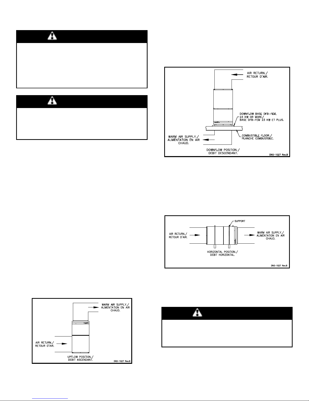
Figure 2 : Downflow installation
2.3.3- Horizontal installation
The return duct may be installed to the back, on the left side, on
the right side or under the unit. The supply duct shall be installed
on the top of the unit.
When the furnace is installed in the horizontal position, either
suspended or on a combustible floor with a choice of right or left
discharge, the clearances from combustible material must be
adhered to. Refer to Figure 3 for additional details.
2.2.2- Supply air ducts
Ducts can be installed with a zero clearance to combustible
material.
2.3- CONFIGURATIONS
This furnace requires suitable ductwork.
2.3.1- Upflow installation
The return duct may be installed to the back, to the bottom, on
the left side, or on the right side of the unit. The supply duct shall
be installed on the top of the unit. Care should be taken not to
damage the wires inside while cutting the opening. Install the
filter rack that is supplied with the unit. It is also recommended
to install the blower door before handling or moving the unit.
Figure 1 : Upflow installation
Figure 3 : Horizontal installation
2.3.4- Suspended installation
The furnace can be hanged to the ceiling in either upflow,
downflow or horizontal. Make sure to mount it appropriately and
to respect the clearances to combustible material.
WARNING
The furnace must be properly secured especially when
installed above living space.
Failure to follow this rule can result in death, bodily injury
and/or property damage.
4
2.4- ELECTRICAL SYSTEM
The SUPREME furnace is completely pre-wired and all field wiring
must be connected to the terminal blocks on the unit. It requires
a 120/240 - 208 volt.
WARNING
RISK OF FIRE
The conductor sizing must conform to the last edition of the
local or national codes.
Failure to follow this rule can result in death, bodily injury
and/or property damage.
Power supply to the unit can be done using copper or aluminum
wires. The wire size must be decided in accordance to the unit
power consumption, the over current protection type and
capacity, the wire type and length, and the environment where
the unit is installed. If an aluminum wire is used, other
precautions must be taken to insure the conformity of the
installation. In all cases, all the factors affecting the wire gauge
must be considered and the installation codes followed.
The exterior of the unit must have an uninterrupted ground to
minimize the risk of bodily harm. A ground terminal is supplied
with the control box for that purpose. A connector is supplied on
the ground terminal to ground an added accessory.
in the supplied manual and connected with the RJ11 wire also
supplied with the interface board.
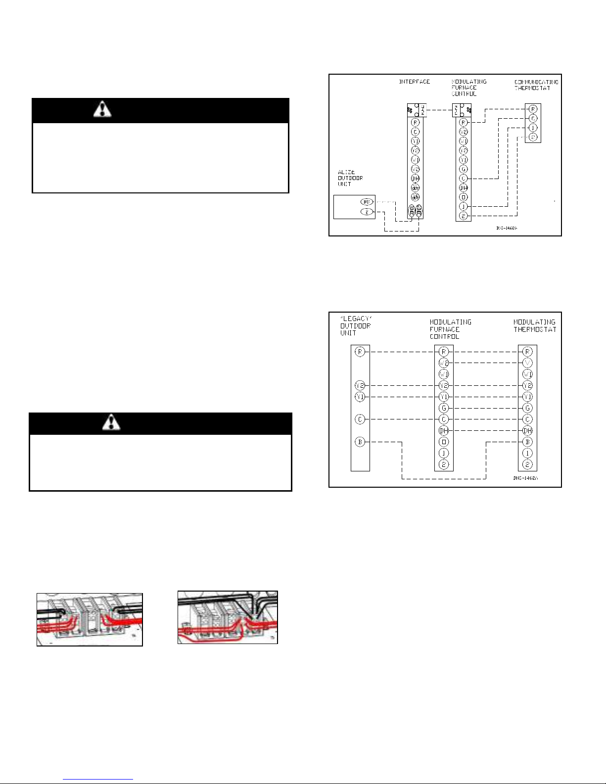
Figure 5 : Communicating thermostat connection
2.5.2- Modulating thermostat
The thermostat must be connected to V/W2, C, R, G terminals
and optionally to Y1, Y2, O and DH terminals if the there are
options of cooling or heat pump.
Figure 6 : Modulating thermostat connection
In the event that wires inside the unit require replacement, these
must be copper wires only with same temperature rating and
sizes as originals.
2.4.1- Conversion from two to one supply wires for model
over 27kW
WARNING
When using one terminal block on models of 27kW and
higher, the installation must be performed with copper wire
ONLY in order to comply with the Canadian electrical code.
The usage of an aluminum or copper wire is acceptable on
models 25kW and lower.
Move all wires from the two pole terminal to the three pole
terminal following the corresponding colors as shown in Figure
4.
The breaker and the supply conductors must be sized by adding
the ampacities of the two terminals indicated on the nameplate.
Refer to the electrical diagram Figure 11.
Figure 4 : Conversion from two to one supply wires
Before After
2.5- INSTALLATION OF THE THERMOSTAT
2.5.1- Communicating thermostat with Alizé system
The thermostat must be connected to terminals 1, 2, R and C of
the furnace. The interface board must be installed as specified
2.5.3- Ducts and filters
The ducts must be sized to accommodate the specified airflow
and the available static pressure. Refer to the applicable local
and/or national installation codes.
Insulate the ducts that lead through non-heated areas. Use
flexible supply and return air connectors to avoid the
transmission of vibration. To make the unit run even quieter, the
installer should:
a. Use two elbows between each outlet and the supply and
return air plenum;
b. Cover the vertical sections of the supply and return air duct
with soundproofing material;
c. Use baffles in short radius elbows;
d. Use flexible hangers to suspend the ducts.
The SUPREME furnace is equipped with a filter frame for the
blower compartment. It must be installed on the outside of one
of the three sides or the bottom of the furnace. Once the location
5
 Loading...