

SUPREME SUP18-A240V12, SUP20-A240V12, SUP23-A240V12, SUP25-A240V12, SUP20-A240V20 Installation Instructions And Homeowner's Manual
...
Models
Caution
: Do not tamper with
ADVANTAGE
(ECM MOTOR)
:
SUPXX-A240V12
SUPXX-A240V20
INSTALLER / SERVICE TECHNICIAN:
USE THE INFORMATION IN THIS MANUAL FOR THE INSTALLATION AND
SERVICING OF THE FURNACE AND KEEP THE DOCUMENT NEAR THE UNIT
FOR FUTURE REFERENCE.
HOMEOWNER:
PLEASE KEEP THIS MANUAL NEAR THE FURNACE FOR FUTURE
REFERENCE.
Printed in Canada
Printed on 100% recycled paper
the unit or its controls. Call a
2015-03-25
qualified service technician.
Manufactured by:
Industries Dettson inc.
3400 Industrial Boulevard
Sherbrooke, Quebec - Canada
J1L 1V8
X40233 Rev. A

TABLE OF CONTENT
1- SAFETY .......................................................... 3
1.1- DANGER, WARNING AND CAUTION ................. 3
1.2- IMPORTANT INFORMATION .............................. 3
1.3- DANGER OF FREEZING ..................................... 3
2- INSTALLATION .............................................. 3
2.1- POSITIONING THE FURNACE ............................ 4
2.2- CLEARANCES TO COMBUSTIBLE MATERIAL 4
2.2.1- Heating unit ................................................................. 4
2.2.2- Supply air ducts .......................................................... 4
2.3- CONFIGURATIONS.............................................. 4
2.3.1- Upflow installation ...................................................... 4
2.3.2- Downflow installation ................................................. 4
2.3.3- Horizontal installation ................................................ 4
2.4- ELECTRICAL SYSTEM ........................................ 4
2.4.1- Conversion from two to one supply wires for model
over 27kW ................................................................................... 5
2.5- INSTALLATION OF THE THERMOSTAT ........... 5
2.5.1- Anticipator adjustment (if required) on thermostat
equipped with heat anticipator adjustment ............................. 6
2.5.2- Ducts and filters .......................................................... 6
2.6- SUPPLY AIR ADJUSTMENTS ............................. 6
2.6.1- HEAT KW/CFM adjustment ........................................ 6
2.6.2- AC/HP size ................................................................... 7
2.6.3- System type ................................................................. 7
2.6.4- AC/HP CFM adjust ...................................................... 7
2.6.5- ON/OFF delay .............................................................. 7
2.6.6- Continuous fan ............................................................ 7
2.6.7- Low-voltage circuit ..................................................... 7
2.6.8- Basic furnace configuration....................................... 7
2.7- INSTALLATION OF ACCESSORIES................... 8
2.7.1- Humidifier and humidistat connection ...................... 8
2.1.1. Electronic Air Cleaner (EAC) connections ............... 8
2.7.2- Dehumidify capability with standard humidistat
connection ................................................................................. 8
2.7.3- Use of a heat pump ..................................................... 8
3- OPERATION ................................................... 8
3.1- START-UP ............................................................ 8
3.2- USE OF MANUAL FURNACE CONTROLS ........ 8
3.3- OPERATING SEQUENCE .................................... 9
3.3.1- Continuous fan ............................................................ 9
3.3.2- Cooling mode – single stage ..................................... 9
3.3.3- Cooling mode – two stage.......................................... 9
3.3.4- Cooling mode – dehumidification ............................. 9
3.3.5- Electric heat heating mode – 1 stage ........................ 9
3.3.6- Electric heat heating mode – 2 stage ......................... 9
3.3.7- Heat pump heating mode – single stage ................... 9
3.3.8- Heat pump heating mode – two stage ....................... 9
3.4- AIRFLOW VERIFICATION................................... 9
3.4.1- Supply Air Temperature Rise Test ........................... 10
3.4.2- High limit verification ................................................ 10
4- MAINTENANCE ............................................ 10
4.1- AIR FILTER ........................................................ 10
4.2- MOTOR LUBRICATION ..................................... 10
5- FURNACE INFORMATION ........................... 11
Table 1: Sequence of operation ......................................... 12
Table 2: Technical specifications ........................................ 13
Table 3: Electric furnace SUP, ECM ½ HP motor, air flow
tables .................................................................................. 14
Table 4: Electric furnace SUP, ECM 1.0 HP motor, air flow
tables .................................................................................. 15
Table 5: Parts list, S
TABLES
UPREME
Advantage ECM .................... 19
FIGURES
Figure 1: Upflow installation .................................................. 4
Figure 2: Downflow installation .............................................. 4
Figure 3: Horizontal installation ............................................. 4
Figure 4 : Conversion from two to one supply wires ............. 5
Figure 5: 1-stage thermostat, electric heating only ............... 5
Figure 6: 2-stage thermostat, electric heating only ............... 5
Figure 7: 1 stage thermostat, electric heat and cooling
application .............................................................................. 5
Figure 8: 2-stage heating & 1-stage air conditioning & heat
pump thermostat .................................................................... 6
Figure 9: 2-stage heating & 2-stage air conditioning & heat
pump thermostat + dehumidification mode ........................... 6
Figure 10 : Fan Control Board ............................................... 6
Figure 11 : Standard humidistat connections ........................ 8
Figure 12 : Thermostat connections ...................................... 8
Figure 12 : Electronic air cleaner connections ...................... 8
Figure 10 : Advantage furnace controls................................. 9
Figure 15 : Furnace dimensions .......................................... 16
Figure 16 : Electrical diagram S
Figure 17: Parts list, S
UPREME
UPREME
Advantage ECM.................. 18
Advantage ECM ... 17
2
1- SAFETY
1.1- DANGER, WARNING AND CAUTION
The words DANGER, WARNING and CAUTION are used to
identify the levels of seriousness of certain hazards. It is
important that you understand their meaning. You will notice
these words in the manual as follows:
DANGER
Immediate hazards which WILL result in death or serious
bodily and/or material damage.
WARNING
Hazards or unsafe practices which CAN result in death or
serious bodily and /or material damage.
CAUTION
Hazards or unsafe practices which CAN result in minor
bodily and /or material damage.
d. Never block or otherwise obstruct the filter and/or
return air openings;
e. Ask the technician installing your furnace to show and
explain to you the following items:
i. The main disconnect switch or circuit breaker;
ii. The air filter and how to change it (check monthly
and clean or replace if necessary);
f. Before calling for service, be sure to have the
information of section 5 of your manual close by in
order to be able to provide the contractor with the
required information, such as the model and serial
numbers of the furnace.
IMPORTANT:
All local and national code requirements
governing the installation of central electric heating equipment,
wiring and the flue connection MUST be followed. Some of the
codes that may apply are:
ANSI/NFPA 70: National Electrical Code
CSA C22.1 or CSA C22.10: Canadian Electrical Code
Only the latest issues of these codes may be used, and are
available from either:
The National Fire Protection Agency
1 Batterymarch Park
Quincy, MA 02269
1.2- IMPORTANT INFORMATION
WARNING
Non-observance of the safety regulations outlined in this
manual will potentially lead to consequences resulting in
death, serious bodily injury and/or property damage.
WARNING
Installation and repairs performed by unqualified persons
can result in hazards to them and to others. Installations
must conform to local codes or, in the absence of such
codes, to codes of the country having jurisdiction.
The information contained in this manual is intended for
use by a qualified technician, familiar with safety
procedures and who is equipped with the proper tools and
test instruments.
Failure to carefully read and follow all instructions in this
manual can result in death, bodily injury and/or property
damage.
a. It is the homeowner’s responsibility to engage a
qualified technician for the installation and subsequent
servicing of this furnace;
b. Do not use this furnace if any part of it was under water.
Call a qualified service technician immediately to
assess the damage and to replace all critical parts that
were in contact with water;
c. Do not store gasoline or any other flammable
substances, such as paper or carton near the furnace;
or
The Canadian Standards Association
178 Rexdale Blvd.
Rexdale, Ontario M9W 1R3
1.3- DANGER OF FREEZING
CAUTION
If your furnace is shut down during the cold weather
season, water pipes may freeze, burst and cause serious
water damage. Turn off the water supply and bleed the
pipes.
If the heater is left unattended during the cold weather season,
take the following precautions:
a. Close the main water valve in the house and purge the
pipes if possible. Open all the faucets in the house;
b. Ask someone to frequently check the house during the cold
weather season to make sure that there is sufficient heat to
prevent the pipes from freezing. Tell this person to call an
emergency number if required.
2- INSTALLATION
This furnace is a true multi-position unit, in that it will function in
an upflow, downflow or horizontal configuration to the left or the
right. Only a few modifications are required during installation
to change from one position to another. The unit is shipped in
the upflow configuration and instructions as to how to change to
the other positions are included in this manual.
3
The unit requires a 120/240 - 208 VAC power supply to the
control panel, thermostat hook-up as shown on the wiring
diagram.
2.1- POSITIONING THE FURNACE
WARNING
Fire and explosion hazard.
The furnace must be installed in a level position, never
where it will slope toward the front.
Do not store or use gasoline or any other flammable
substances near the furnace.
Non-observance of these instructions will potentially result
in death, bodily injury and/or property damage.
CAUTION
This furnace is not watertight and is not designed for
outdoor installation. It must be installed in such a manner
as to protect its electrical components from water. Outdoor
installation will lead to a hazardous electrical condition and
to premature failure of the equipment.
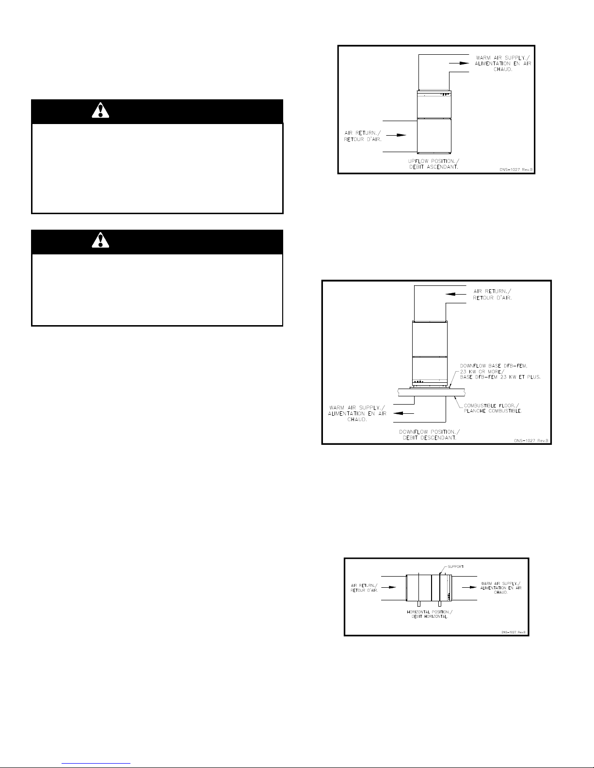
Figure 1: Upflow installation
2.3.2- Downflow installation
The return duct may be installed to the back, on the left side, on
the right side or under the unit. The supply duct shall be installed
on the top of the unit.
When the furnace is installed in the downflow position on a
combustible floor. The downflow base DFB-SUP can be used.
Refer to Figure 2 and the installation instructions provided with
the base.
Figure 2: Downflow installation
If the furnace is installed in a basement or on a dirt floor, in a
crawl space for example, it is recommended to install the unit on
a cement base 2.5 cm to 5.0 cm (1’’ to 2’’) thick.
In addition, the heater should also be located close to the center
of the air distribution system.
2.2- CLEARANCES TO COMBUSTIBLE MATERIAL
2.2.1- Heating unit
The furnace is approved for zero clearance to combustible
material regardless of the heating capacity.
2.2.2- Supply air ducts
Ducts can be installed with a zero clearance to combustible
material.
2.3- CONFIGURATIONS
This furnace requires suitable ductwork.
2.3.1- Upflow installation
The return duct may be installed to the back, to the bottom, on
the left side, or on the right side of the unit. The supply duct shall
be installed on the top of the unit. Care should be taken not to
damage the wires inside while cutting the opening. Install the
filter rack supplied with the unit according to the instructions
provided with it. It is also recommended to install the blower
door before handling or moving the unit. Refer to Figure 1 for
additional details.
2.3.3- Horizontal installation
The return duct may be installed to the back, on the left side, on
the right side or under the unit. The supply duct shall be installed
on the top of the unit.
When the furnace is installed in the horizontal position, either
suspended or on a combustible floor with a choice of right or left
discharge, the clearances from combustible material must be
adhered to. Refer to Figure 3 for additional details.
Figure 3: Horizontal installation
2.4- ELECTRICAL SYSTEM
The S
UPREME
furnace is completely pre-wired and all field wiring
must be connected to the terminal blocks on the unit. It requires
a 120/240 - 208 volt.
4

WARNING
Risk of fire.
The conductor sizing must conform to the last edition of the
local or national codes.
Failure to follow this rule can result in death, bodily injury
and/or property damage.
Power supply to the unit can be done using copper or aluminum
wires. The wire size must be decided in accordance to the unit
power consumption, the over current protection type and
capacity, the wire type and length, and the environment where
the unit is installed. If an aluminum wire is used, other
precautions must be taken to insure the conformity of the
installation. In all cases, all the factors affecting the wire gauge
must be considered and the installation codes followed.
The exterior of the unit must have an uninterrupted ground to
minimize the risk of bodily harm. A ground terminal is supplied
with the control box for that purpose. A connector is supplied on
the ground terminal to ground an added accessory.
In the event that wires inside the unit require replacement, these
must be copper wires only with same temperature rating and
sizes as originals.
2.5- INSTALLATION OF THE THERMOSTAT
A thermostat must be installed to control the temperature of the
area to be heated. Follow the instructions supplied with the
thermostat. Some thermostats need to connect the C terminal
on the furnace and thermostat. Install the thermostat on an
interior wall in a location where it will not be subject to direct
sunlight, lamps, air diffusers, fireplaces, etc. Seal openings in
walls to avoid air currents that may influence the operation of the
thermostat. Also refer to the wiring diagrams provided with the
heating/air conditioning unit. The connections must be made as
indicated on Figure 5 to Figure 9. Refer to the electrical diagram
(Figure 16
).
Figure 5: 1-stage thermostat, electric heating only
2.4.1- Conversion from two to one supply wires for
model over 27kW
Warning – When using one terminal block on models over
27kW, the installation must be performed with copper wire
ONLY in order to comply with the Canadian electrical code. The
usage of an aluminum or copper wire is acceptable on models
25kW and lower.
Move all wires from the two pole terminal to the three pole
terminal following the corresponding colors as shown in Figure
4.
The breaker and the supply conductors must be sized by adding
the ampacities of the two terminals indicated on the nameplate.
Refer to the electrical diagram Figure 16.
Figure 4 : Conversion from two to one supply wires
Before After
Figure 6: 2-stage thermostat, electric heating only
Figure 7: 1 stage thermostat, electric heat and cooling
application
5
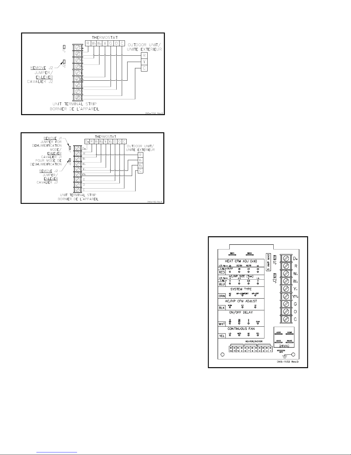
Figure 8: 2-stage heating & 1-stage air conditioning & heat
pump thermostat
Figure 9: 2-stage heating & 2-stage air conditioning & heat
pump thermostat + dehumidification mode
2.5.1- Anticipator adjustment (if required) on thermostat
equipped with heat anticipator adjustment
Some thermostats are equipped with a heat anticipator that must
be adjusted according to the instructions supplied. This is to
ensure that the heating mode is comfortable and economical.
Generally speaking, on a single stage thermostat, a reading of
the current must be taken with an ammeter as follows:
1. Move the anticipator to its highest setting, rendering it
ineffective.
2. Remove the wire from the W1 terminal and connect an
ammeter between the terminal and the wire.
3. Call for heat by raising the set point on the thermostat and
allow the furnace to run for 3 to 4 minutes to reach its peak
output.
4. Once the current has stabilized, a reading should be taken
and the anticipator adjusted to that value. If longer heating
cycles are desired, the anticipator can be set to a higher
value
b. Cover the vertical sections of the supply and return air duct
with soundproofing material;
c. Use baffles in short radius elbows;
d. Use flexible hangers to suspend the ducts.
The S
UPREME
blower compartment. It must be installed on the outside of one
of the three sides or the bottom of the furnace. Once the location
of the installation has been determined, use the four square
knockouts for ease of cutting the opening.
A heat pump or an air conditioner can be added to this furnace,
in either the supply or return air duct. Carefully follow the
instructions provided with these appliances to ensure proper
installation and hook-up to the electric furnace. Refrigerant and
drainage pipes must in no way hinder access to the furnace
panels.
furnace is equipped with a filter frame for the
2.6- SUPPLY AIR ADJUSTMENTS
Fan Control Board taps are used by the installer to configure a
system. The ECM motor uses the selected taps to modify its
operation to a pre-programmed table of airflows (Refer to Table
3 and Table 4). Airflows are based on system size or mode of
operation and those airflows are modified in response to
thermostat inputs.
SUP electric furnace must be configured to operate properly with
system components with which it is installed. To successfully
configure a basic system (see information printed on circuit
board label located next to select pins), move the 6 select wires
to the pins which match the components used. (Refer to Figure
10 below)
Figure 10 : Fan Control Board
2.5.2- Ducts and filters
The ducts must be sized such a way as to accommodate the
specified airflow and the available static pressure. Refer to the
applicable local and/or national installation codes.
Insulate the ducts that lead through non-heated areas. Use
flexible supply and return air connectors to avoid the
transmission of vibration. To make the unit run even quieter, the
installer should:
a. Use two elbows between each outlet and the supply and
return air plenum;
2.6.1- HEAT KW/CFM adjustment
Installer must verify (factory set) the electric heat airflow
adjustment required for kW size heater installed.
The select pins are marked 25, 23/20, 18/15, 10 (for ½ HP ECM
motor unit) and 30/27, 25, 23, 20, (for 1.0 HP ECM motor unit).
6
 Loading...