

SUPREME RO5 PREMIUM, RO5, RO7 PREMIUM, RO7, RO6 PREMIUM Installation Manual
...
www.supremefilters.com
Installation Manual
Instrukcja montażu


Important information............................................................................................4
Working conditions and requirements.....................................................................4
Technical specification and requirements................................................................5
System components................................................................................................6
Additional components present in the packaging....................................................7
Connection diagram - SUPREME-RO5 PREMIUM system.........................................8
Connection diagram - SUPREME-RO5 system..........................................................9
Connection diagram - SUPREME-RO6 PREMIUM system.......................................10
Connection diagram - SUPREME-RO6 system........................................................11
Connection diagram - SUPREME-RO6-P system.....................................................12
Connection diagram - SUPREME-RO7 PREMIUM system.......................................13
Connection diagram - SUPREME-RO7 system........................................................14
System installation................................................................................................15
System use.............................................................................................................21
System use - cartridge replacement.......................................................................22
System use - membrane replacement....................................................................23
System use - linear cartridge replacement.............................................................24
Questions and answers..........................................................................................26
User’s manual for Reverse osmosis systems
3
EN

- Before star ting the system installation , it is
recommended to read and apply the instructions referred
to in the document. It contains important information on
safety, installation, operation and maintenance of the
product. The system which you are holding may slightly
differ from the one presented on the photographs,
illustrations present in the manual.
- Non-observance of the manual may be the reason for
equipment or property damage. Only proper installation
and use ensures long-term troubleless operation of the
system.
- The device is designed for the purposes of water
filtration. Manufacturer and distributor shall not be
responsible for using the system in the way which was not
intended.
- The system may be installed on your own. All electric and
waterworks connections have to be performed in
accordance with local regulations.
- Before the system installation, one shall check whether
there are not any visible external damages, it is not
allowed to install a damaged device.
WORKING PRESSURE: min. 3 / max. 6 bars (43 psi - 87 psi)
- lower or higher working pressure may have a negative impact on the operation of the whole device. If pressure is higher
than the maximum one, it is necessary to apply a pressure regulator before the system.
- check water pressure regularly.
- bear in mind that water pressure at night may be significantly higher than during the day.
- if pressure in the system is below the minimum level, one shall consider buying a pump intended for cooperation with RO
systems which increases the pressure or a system which is equipped in SUPREME-RO6-P pump.
WORKING TEMPERATURE: min. 4°C / max. 30°C (39°F - 86°F)
- do not install the water filtration system in the environment which is exposed to high temperatures
(e.g. non-ventilated boiler houses) or to temperatures which cause freezing.
- the system may not be exposed to contact with atmospheric conditions such as direct sun rays or rainfalls.
- do not install the water filtration system near the water heater.
ELECTRIC CONNECTION:
- SUPREME RO6-P water system works with 24V power supply and it is equipped in a 110-240/24V-50/60Hz transformer;
one shall always use the transformer which was supplied with the device.
- make sure that the transformer is connected to the power supply socket which was installed in dry surrounding with
applicable nominal parameters and overcurrent protection.
- Store the user’s manual in a safe place and make sure that
new users have familiarized with it.
- The Reverse osmosis system was designed and
manufactured in accordance with the most recent safety
requirements and regulations. Inadequate repairs may be
the reason of unplanned hazard for users, which the
manufacturer is not responsible for. In connection with
the above, all repairs shall be carried out by a competent
employee, especially trained for it, who knows the
product.
- Devices such as a pump and transformers shall be utilized
in accordance with the requirements for electric and
electronic wastes. In order to ensure it, one shall act in
accordance with valid national and local regulations.
- If non-original spare parts are applied, the manufacturer
and distributor shall not be held responsible for incorrect
system operation or for any possible damages.
1. IMPORTANT INFORMATION
2. WORKING CONDITIONS AND REQUIREMENTS
User’s manual for Reverse osmosis systems
4
3. TECHNICAL SPECIFICATION AND REQUIREMENTS
Parametr
RO system supply water parameters
Supply pressure (systems without a pump), bar (psi)
3 - 6* (43-87)
2 - 4.5 (29-65)
0.4 - 0.6** (5.8-8.7)
pH
6.5 - 8.5
< 1500 ppm
<500 ppm CaCO (<28 °dH)
3
<0.5 ppm
<0.3 ppm
<0.1 ppm
<50 CFU/mL
Supply pressure (systems with a pump), bar (psi)
TDS
Air pressure in the tank, bar (psi)
Hardness
Supply water temperature °C (°F)
+4…+30*** (39...86)
+5…+40*** (+41...+104)
SUPREME RO5: 400 X 450 X150
SUPREME RO6: 450 X 450 X150
SUPREME RO6P: 500 X 450 X150
SUPREME RO7: 500 X 450 X150
SUPREME RO5 PREMIUM: 350 x 450 x150
SUPREME RO6 PREMIUM: 400 x 450 x150
SUPREME RO7 PREMIUM: 450 x 450 x150
Free chlorine
Ambient temperature, °C (°F)
Iron
Water connection (inches)
3/8
Manganese
Total bacteria count
E. Coli load
<3
Reference system dimensions: height x width x depth (mm)
Tank dimensions: height x width x depth (mm)
Value
Value*
350 x 260 x 260
* if supply water pressure is below the required value, it is necessary to buy such a system which is equipped with a pump (SUPREME RO6-P) or buy a pressure
booster pump separately which is intended for working with RO systems. If the pressure in the waterworks system exceeds the top limit, it is necessary to install a
pressure regulator on the main pipe.
** if pressure in the tank is beyond the aforementioned range, it is necessary to pump or release air to the normative value.
*** if supply water temperature increases within the range from +20 ... + 30°C (+68 ... + 86°F), the rejection of contamination will be decreased and system efficiency
will increase at the same time causing TDS growth. It is not recommended to use the system with water temperature exceeding + 30°C (+ 86°F).
If water does not meet the above requirements, the shelf life of the cartridges and membranes may be reduced.
* if the house is supplied with water from own water intake or from waterworks, perform a water laboratory test before installing the Reverse osmosis system.
If any of water indexes exceeds the limit, one shall consider using the pre-filtration system before the Reverse osmosis system. In order to do it, one shall contact
with a specialized company which deals with water treatment. A list of companies is published at www.supremefilters.com
5
User’s manual for Reverse osmosis systems
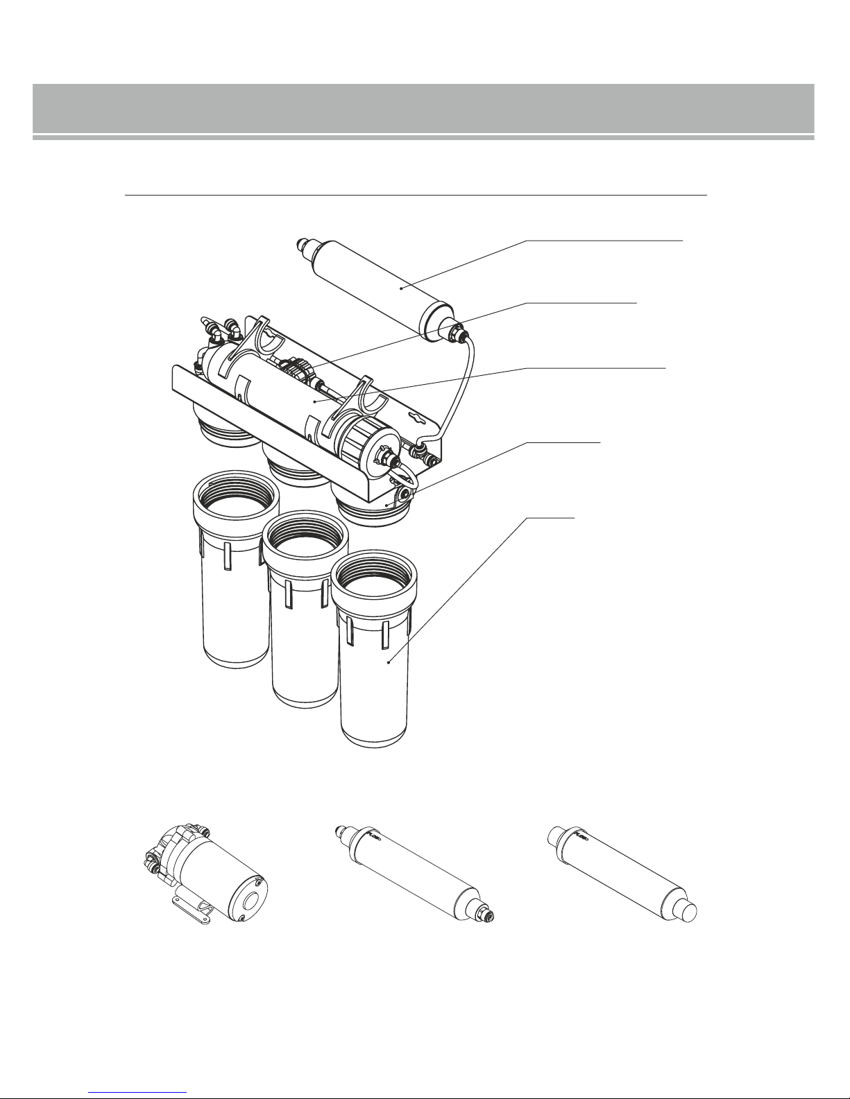
4. SYSTEM COMPONENTS
Based on SUPREME-RO5 PREMIUM system
Option
1
Pump
2
Mineralizing cartridge
3
Bioceramic cartridge
Linear cartridge with activated carbon
Membrane housing
Filter header**
Filter housing*
* depending on the system version, the headers and housing may differ from each other.
Four-way valve
1
SUPREME RO6-P
2
SUPREME RO6, SUPREME RO6-P, SUPREME RO6 PREMIUM, SUPREME RO7, SUPREME RO7 PREMIUM
3
SUPREME RO7, SUPREME RO7 PREMIUM
6
User’s manual for Reverse osmosis systems

5. ADDITIONAL COMPONENTS PRESENT IN THE PACKAGING
Tank
Faucet*
Chrome plated water connection
3/8" FIP x 3/8" MIP x 1/4" FIP
Tank valve
Ball valve
Installation tube
Drain yoke
Cartridge Set
Cartridge made of polypropylene non-woven fabric 5 mic.
Carbon block
Cartridge made of polypropylene non-woven fabric 20 mic.
Osmotic membrane
Wrench for membrane housing
Wrench used with a housing Wrench used with
a quick-coupling**
* depending on the model, it may be a single- or double-circuit faucet.
** SUPREME ROX PREMIUM systems
Teflon tape
User’s manual
7
User’s manual for Reverse osmosis systems
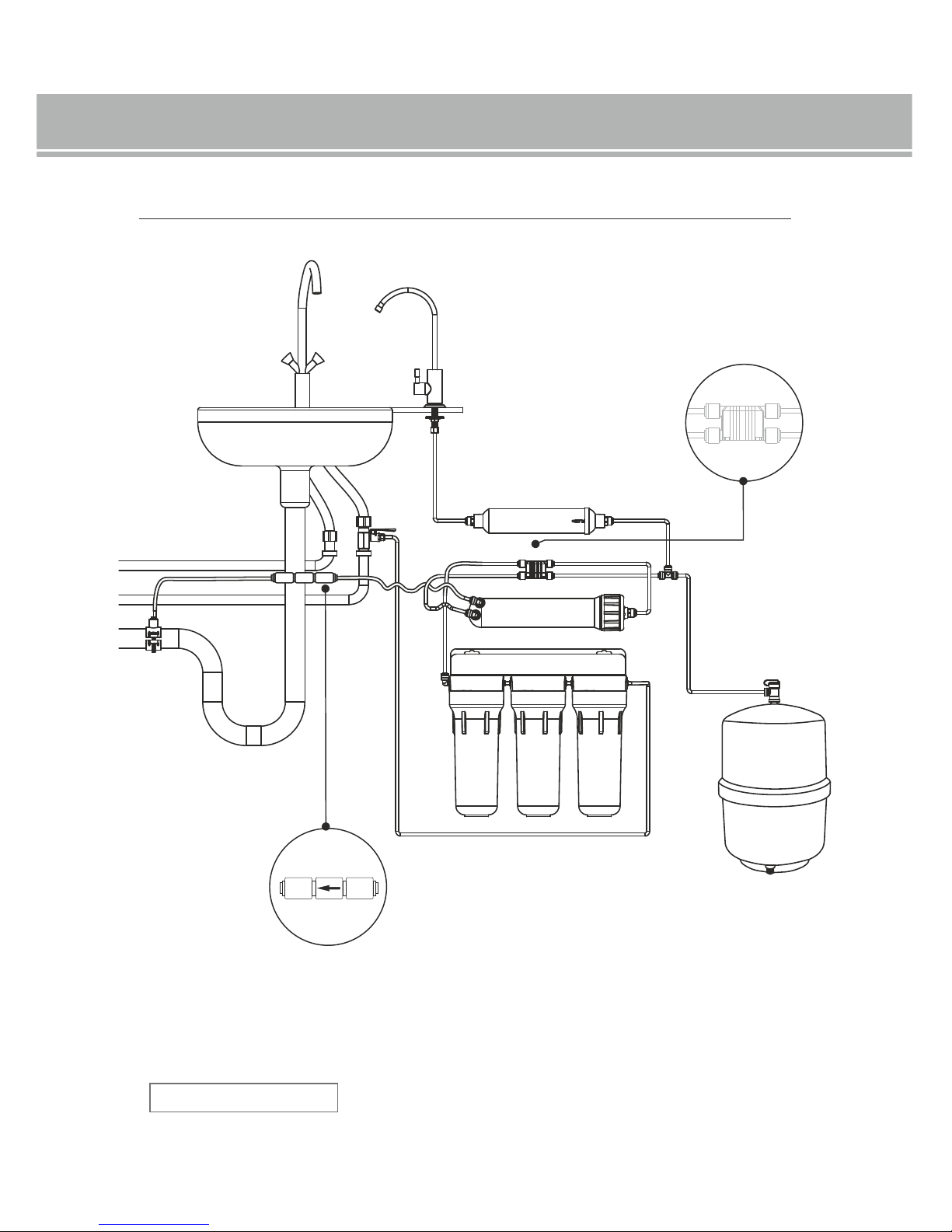
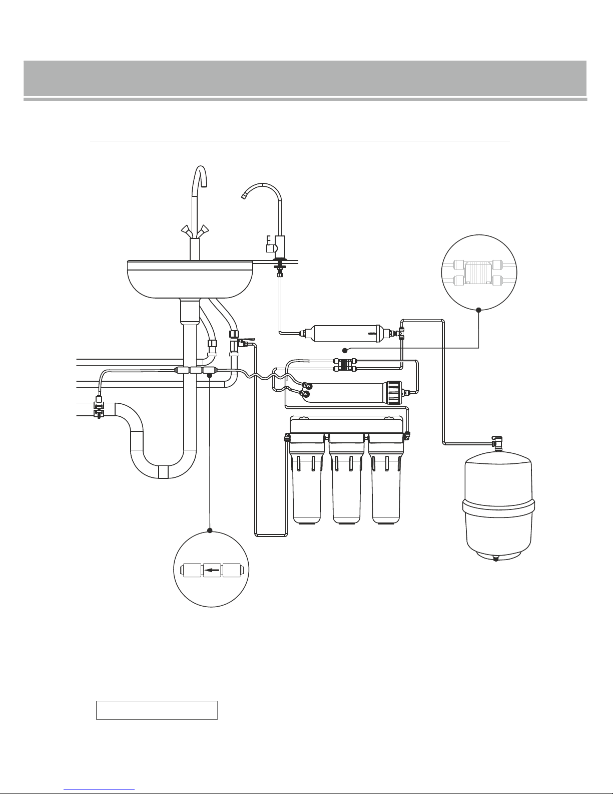
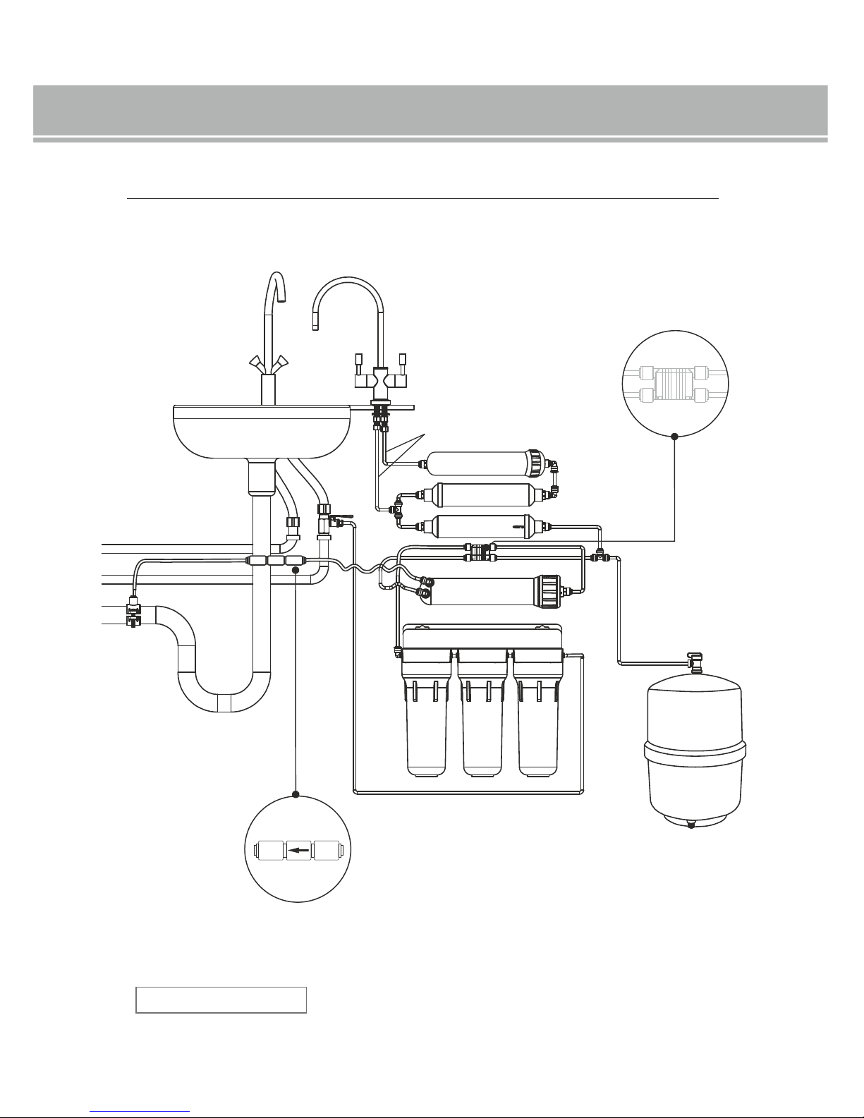
6. CONNECTION DIAGRAM - SUPREME-RO5 PREMIUM SYSTEM
raw water inlet to the system
drain leading to the outlet
water inlet to the tank
pure water outlet
SUPREME-RO5 PREMIUM
Model
The manufacturer reserves the right to modify the product or its components.
1
2
3
4
IN
OUT
8
In the event it is necessary to replace the flow restrictor, the flow
restrictor has to be installed in accordance with the flow direction.
In the case it is necessary to replace a four-way valve, the valve has to be
installed in accordance with IN/OUT designations.
1. Water inlet to the valve from the third housing.
2. Water outlet to the membrane from the four-way valve.
3. Pure water inlet to the four-way valve (water which passed RO membrane).
4. Water outlet to the linear carbon cartridge tripod.
User’s manual for Reverse osmosis systems
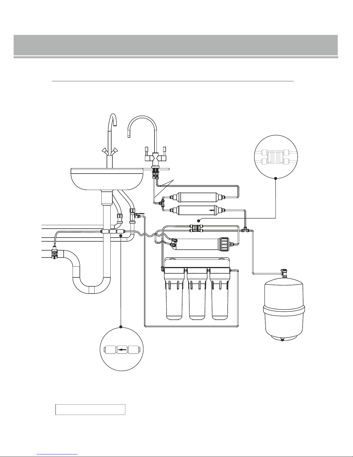
6.1. CONNECTION DIAGRAM - SUPREME-RO5 SYSTEM
SUPREME-RO5
Model
1
2
3
4
IN
OUT
9
raw water inlet to the system
drain leading to the outlet
water inlet to the tank
pure water outlet
The manufacturer reserves the right to modify the product or its components.
In the event it is necessary to replace the flow restrictor, the flow
restrictor has to be installed in accordance with the flow direction.
In the case it is necessary to replace a four-way valve, the valve has to be
installed in accordance with IN/OUT designations.
1. Water inlet to the valve from the third housing.
2. Water outlet to the membrane from the four-way valve.
3. Pure water inlet to the four-way valve (water which passed RO membrane).
4. Water outlet to the linear carbon cartridge tripod.
User’s manual for Reverse osmosis systems
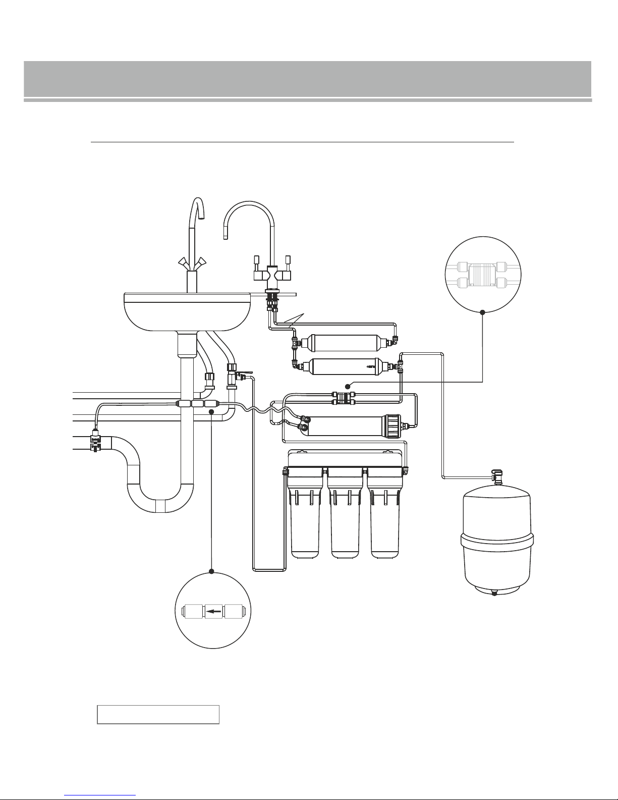
6.2. CONNECTION DIAGRAM - SUPREME-RO6 PREMIUM SYSTEM
SUPREME-RO6 PREMIUM
Model
1
2
3
4
IN
OUT
10
raw water inlet to the system
drain leading to the outlet
water inlet to the tank
pure water outlet
The manufacturer reserves the right to modify the product or its components.
In the event it is necessary to replace the flow restrictor, the flow
restrictor has to be installed in accordance with the flow direction.
In the case it is necessary to replace a four-way valve, the valve has to be
installed in accordance with IN/OUT designations.
1. Water inlet to the valve from the third housing.
2. Water outlet to the membrane from the four-way valve.
3. Pure water inlet to the four-way valve (water which passed RO membrane).
4. Water outlet to the linear carbon cartridge tripod.
User’s manual for Reverse osmosis systems
SUPREME-RO6
Model
6.3. CONNECTION DIAGRAM - SUPREME-RO6 SYSTEM
1
2
3
4
IN
OUT
11
raw water inlet to the system
drain leading to the outlet
water inlet to the tank
pure water outlet
The manufacturer reserves the right to modify the product or its components.
In the event it is necessary to replace the flow restrictor, the flow
restrictor has to be installed in accordance with the flow direction.
In the case it is necessary to replace a four-way valve, the valve has to be
installed in accordance with IN/OUT designations.
1. Water inlet to the valve from the third housing.
2. Water outlet to the membrane from the four-way valve.
3. Pure water inlet to the four-way valve (water which passed RO membrane).
4. Water outlet to the linear carbon cartridge tripod.
User’s manual for Reverse osmosis systems
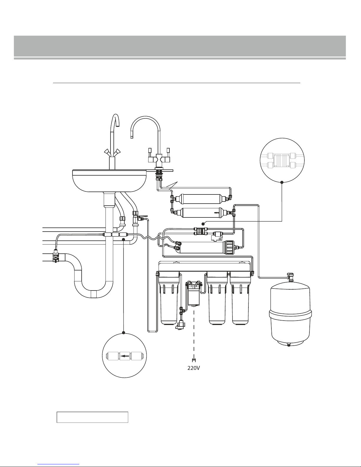
SUPREME RO6-P
Model
6.4. CONNECTION DIAGRAM - SUPREME-RO6-P SYSTEM
1
2
3
4
IN
OUT
12
raw water inlet to the system
drain leading to the outlet
water inlet to the tank
pure water outlet
The manufacturer reserves the right to modify the product or its components.
In the event it is necessary to replace the flow restrictor, the flow
restrictor has to be installed in accordance with the flow direction.
In the case it is necessary to replace a four-way valve, the valve has to be
installed in accordance with IN/OUT designations.
1. Water inlet to the valve from the third housing.
2. Water outlet to the membrane from the four-way valve.
3. Pure water inlet to the four-way valve (water which passed RO membrane).
4. Water outlet to the linear carbon cartridge tripod.
User’s manual for Reverse osmosis systems
6.5. CONNECTION DIAGRAM - SUPREME-RO7 PREMIUM SYSTEM
SUPREME-RO7 PREMIUM
Model
1
2
3
4
IN
OUT
13
raw water inlet to the system
drain leading to the outlet
water inlet to the tank
pure water outlet
The manufacturer reserves the right to modify the product or its components.
In the event it is necessary to replace the flow restrictor, the flow
restrictor has to be installed in accordance with the flow direction.
In the case it is necessary to replace a four-way valve, the valve has to be
installed in accordance with IN/OUT designations.
1. Water inlet to the valve from the third housing.
2. Water outlet to the membrane from the four-way valve.
3. Pure water inlet to the four-way valve (water which passed RO membrane).
4. Water outlet to the linear carbon cartridge tripod.
User’s manual for Reverse osmosis systems

SUPREME-RO7
Model
6.6. CONNECTION DIAGRAM - SUPREME-RO7 SYSTEM
1
2
3
4
IN
OUT
14
raw water inlet to the system
drain leading to the outlet
water inlet to the tank
pure water outlet
The manufacturer reserves the right to modify the product or its components.
In the event it is necessary to replace the flow restrictor, the flow
restrictor has to be installed in accordance with the flow direction.
In the case it is necessary to replace a four-way valve, the valve has to be
installed in accordance with IN/OUT designations.
1. Water inlet to the valve from the third housing.
2. Water outlet to the membrane from the four-way valve.
3. Pure water inlet to the four-way valve (water which passed RO membrane).
4. Water outlet to the linear carbon cartridge tripod.
User’s manual for Reverse osmosis systems
7. SYSTEM INSTALLATION
NOTE! Before starting the device installation, read the manual carefully.
Information about working with a quick-coupling.
Check whether all the elements are in the packaging. Do not open the cartridges or accessories without making sure that
everything has been supplied with the system. If any of the elements is missing, please contact the distributor which you
bought the device from.
Before attempting the installation, check pressure in the water system (min. 3 bars - max. 6 bars).
Before attempting the system installation, check pressure in the tank (correct pressure - 0.4-0.6 bar).
Before attempting the installation, check whether the raw water meets the requirements - see item 3 “TECHNICAL
SPECIFICATION AND REQUIREMENTS”.
Before attempting the installation check whether there is enough space in the closet in which the system will be installed.
If there is sufficient place for the filtration part only, install the tank in a separate closet.
Safety warning: in the case of osmotic systems equipped with a pump, one shall make sure that the transformer is
connected to the power supply socket which was installed in a dry environment and with applicable nominal parameters
and overcurrent protection.
The system shall be installed in accordance with the guidelines listed in the manual.
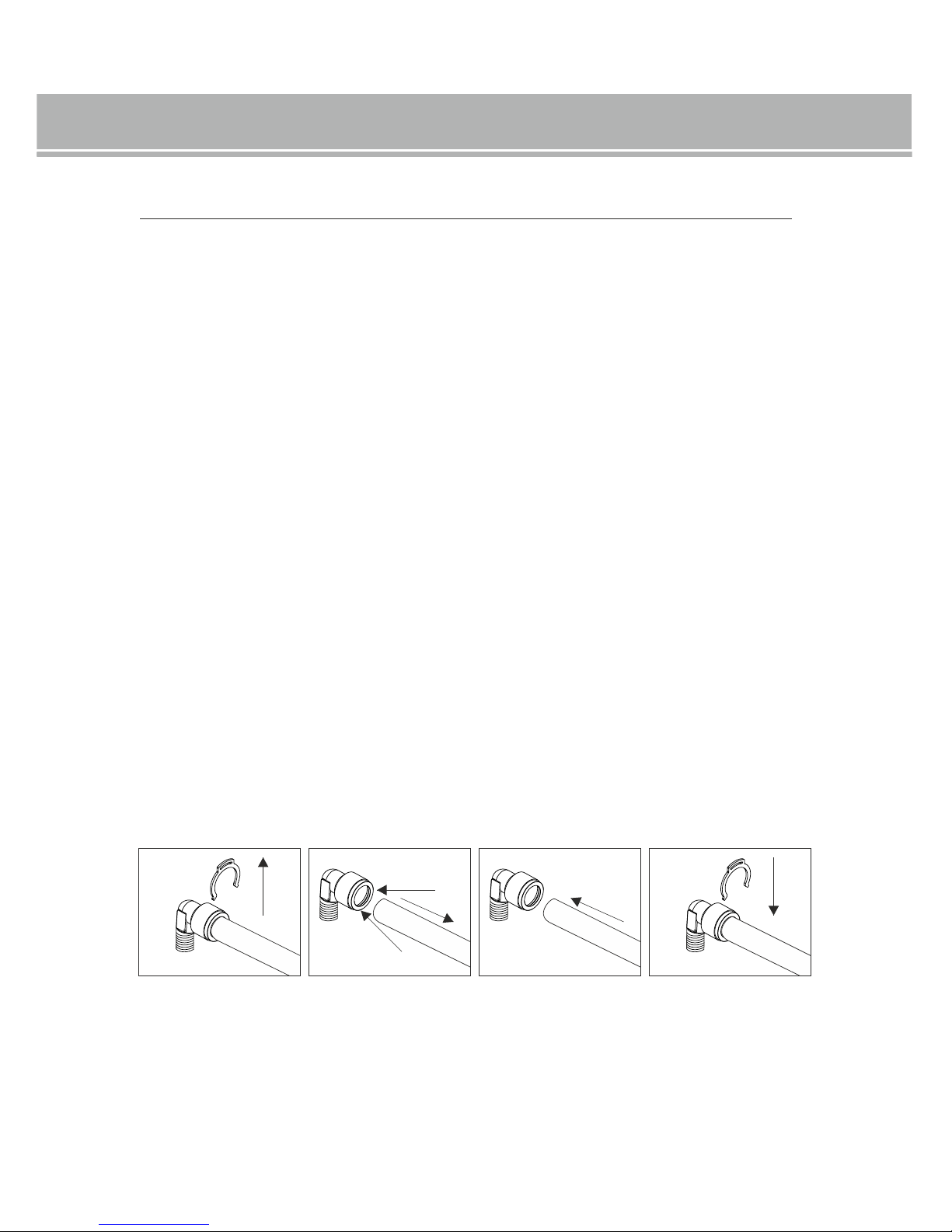
Tube taking off:
1) Take off the protective clip from the quick-coupling (Fig. 1).
2) Press the quick-coupling flange symmetrically and take out the tube (Fig. 2).
Tube attaching:
1) Push the tube into the quick-coupling (Fig. 3).
2) Secure the connection with a clip (Fig. 4).
Important information:
The system has been tested by its manufacturer in terms of tightness, the presence of remaining water is allowed.
Before the system installation and contacting with cartridges as well as osmotic membrane, wash hands thoroughly
with anti-bacterial soap. Use latex gloves (not included in the set) for the purposes of the assembly.
Fig. 1
Fig. 2
Fig. 3 Fig. 4
15
User’s manual for Reverse osmosis systems
16
Step 1: Take out the system from the packaging, then check the device and tank in terms of damages. NOTE! Do not install
a damaged device.
Step 2: Close the main water valve. Then, open the tap for 1 minute in order to release pressure and close the tap.
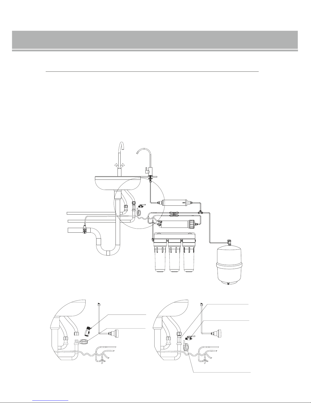
Step 3. Screw in the adaptation connection for cold water system. Screw in the shut-off valve to water adaptation
connection. Use Teflon tape for sealing the threaded connections.
Figure 1 Figure 2
adaptation connection
adaptation connection
Teflon tape
ball valve
Teflon tape
7. SYSTEM INSTALLATION
User’s manual for Reverse osmosis systems
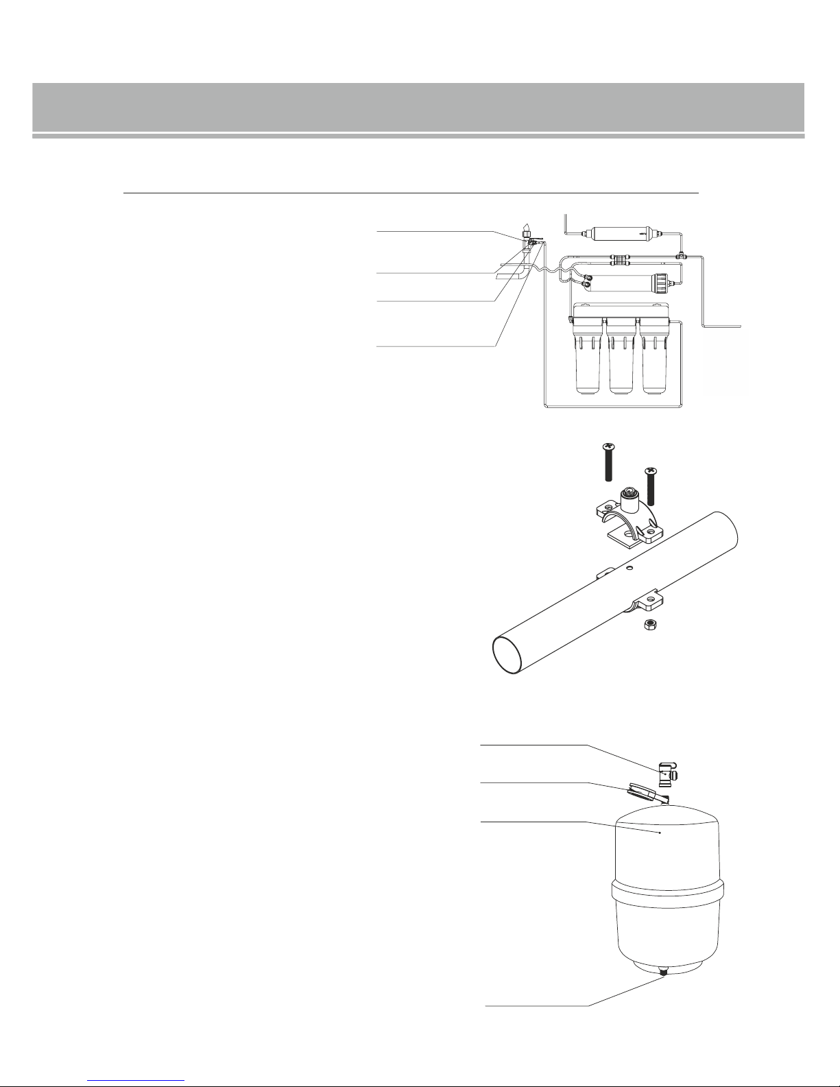
Step 6: Put a few layers of Teflon tape on the tank neck, then put a valve
on the tank. Make sure that the valve is in closed position. Important
information! While screwing the valve, be careful not to overtighten it.
Important information! Check air pressure in an empty tank.
The correct pressure in the tank shall be 0.4-0.6 bar (5.8-8.7 psi).
If the pressure in the tank is below the minimum level: fill in the tank
with the air using a compressor equipped with a pressure gauge.
If the pressure in the tank is above the maximum level: push the neck
located in the lower part of the tank, release some air in order to reduce
the pressure, then connect the pressure gauge and check whether its
value is within the range of 0.4-0.6 bar.
tank valve
Teflon tape
water container
tank air valve
17
Step 4: Unscrew the nut from the shut-off valve
and put it on the tube. Put the tube on the valve
neck, then thoroughly tighten the connection.
Connect the other end of the tube to the water
inlet elbow to the system.
adaptation connection
ball valve
nut
tube
Step 5: Install the drain yoke with the drain pipe from the washbasin.
The yoke conforms to most standard drain pipes.
Drill a hole with 5.0 mm (0.2”) diameter in the drain pipe and then,
place a sticky gasket. Assemble and tighten the yoke. Connect the tube
to the yoke and its other end shall be connected with the system flow
restrictor. Secure the connections with a clip.
User’s manual for Reverse osmosis systems
7. SYSTEM INSTALLATION
 Loading...