

Page 1

AUTO LENS EDGER
ALE-1600 Operation Manual (V2.0)
Shanghai Supore Instruments Co.,LTD.
http://www.supore.com
REV.20190125
Page 2

Preface
Dear respected user:
Thank you for choosing our product and trusting our company.
ALE-1600 patternless lens edger is developed specially for optical
shops to edge the lens.
Please read the manual carefully and put it near the edger for easy
reference.
Information of the manual doesn’t have nature of the contract, thus can
be modified without prior notice. The content has been checked strictly
to make sure no errors. But it’s impossible to avoid error or omissions
so we are responsible for further update.
If user have not operated properly according to this manual and leads
to edger problem, then we will not include the problem in the scope of
our factory’s warranty.
Attention:
ALE-1600G with grooving and safe chamfering function;
- 1 -
Page 3
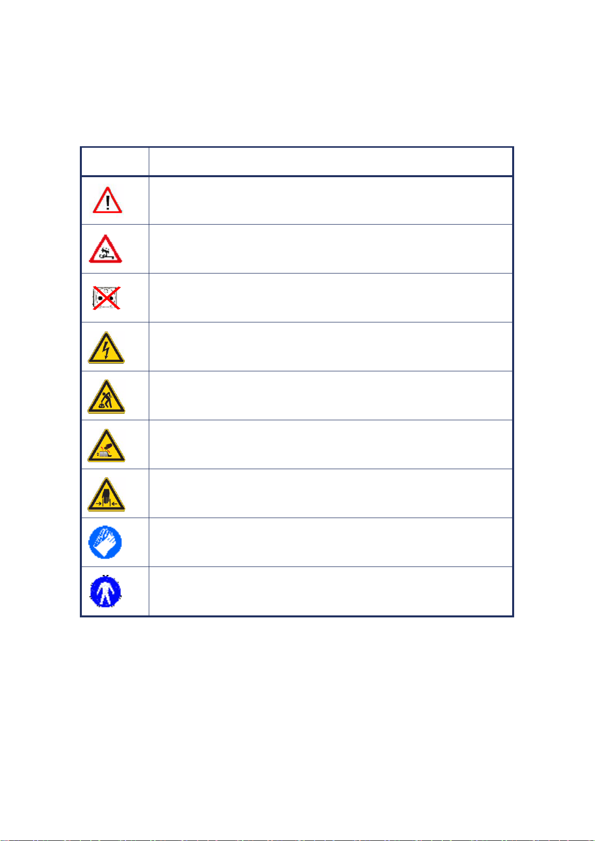
DESCRIPTION OF SYMBOLS
Symbol
Description
Important warning, marking the meaning is: if the violation, inappropriate
operation of the machine, and the risk of serious damage to the existence of
life. Please read carefully.
Import suggestion: may damage the machine or cause problem. Please read
carefully.
Necessary preparation
Before any operation, make sure power is off.
Electrical problem.
Heavy product reminder
The machine is heavy and requires more than two people to carry it.
Rotate reminder:
Don’t put hands near the rotating wheels.
Pinching hands reminder:
Please pay special attention when clamping lens.
Must wear protective gloves
Especially when cleaning and changing the water tank.
Must ware work clothes,
Especially when cleaning and changing the water tank.
Different symbols in manual can draw attention of users and can distinguish different
matters.(e.g. matters related to safety)
Following diagram have lists all symbols and descriptions:
- 2 -
Page 4

CONTENT
Preface ......................................................................................................................................................... - 1 -
1. ASSEMBLING ......................................................................................................................................... - 5 -
1.1 Open the packaging of machine .................................................................................................... - 6 -
1.1.1 Warning .............................................................................................................................. - 6 -
1.1.2 Procedure ........................................................................................................................... - 6 -
1.2 remove the fixed transportation rails ............................................................................................ - 7 -
1.2.1 Condition ............................................................................................................................ - 7 -
1.2.2 Procedure ........................................................................................................................... - 7 -
1.3 prepare the working table ............................................................................................................. - 8 -
1.3.1 Machine specification ......................................................................................................... - 8 -
1.3.2 Working table size and drilling hole rerquirement ............................................................. - 9 -
1.4 Water supplying system .............................................................................................................. - 10 -
1.4.1 Description ....................................................................................................................... - 10 -
1.4.2 Piper connectioin .............................................................................................................. - 10 -
1.5 Electrical connection ................................................................................................................... - 13 -
1.5.1 Electrical wire of the edger ............................................................................................... - 13 -
1.6 Start the edger ............................................................................................................................. - 14 -
2. SAFETY PRECAUTIONS ...................................................................................................................... - 15 -
2.1 Notice .......................................................................................................................................... - 15 -
2.1.1 Operator ........................................................................................................................... - 15 -
2.1.2 Machine ............................................................................................................................ - 15 -
2.2 Suggestions .................................................................................................................................. - 16 -
3. USE OF EDGER ................................................................................................................................... - 17 -
3.1. Appearance................................................................................................................................. - 17 -
3.1.1 Appearance of the edger .................................................................................................. - 17 -
3.2 INTRODUCTION OF OPERATE INTERFACE .................................................................................... - 18 -
3.2.1Display interface ................................................................................................................ - 18 -
3.2.2 Screen 1:1display .............................................................................................................. - 19 -
3.2.3 Optical scanner system ..................................................................................................... - 20 -
3.2.4 Change shape of pattern data .......................................................................................... - 22 -
3.2.5 Pick up stored data ........................................................................................................... - 24 -
3.2.6 Fix center of lens, put the suction cup on lens ................................................................. - 25 -
3.2.7 Edging lens interface ........................................................................................................ - 28 -
3.3 Lens processing............................................................................................................................ - 29 -
3.3.1 Clamp/remove the lenses ................................................................................................. - 29 -
3.3.2 Start/stop the grinding procedure .................................................................................... - 30 -
3.3.3 Lens processing steps ....................................................................................................... - 30 -
3.3.4 Processing range ............................................................................................................... - 33 -
4. CONFIGURATION MENU .................................................................................................................... - 34 -
4.1 Configuration menu introduction ................................................................................................ - 34 -
4.1.1 System menu interface ..................................................................................................... - 34 -
4.1.2 Calibrate size of scanner ................................................................................................... - 35 -
4.1.3 Optical blocker calibration ................................................................................................ - 35 -
4.1.4 The test menu ................................................................................................................... - 36 -
4.1.5 Setting menu .................................................................................................................... - 38 -
4.1.6 Initial parameter setting ................................................................................................... - 39 -
4.1.7 Processing statistics table ................................................................................................. - 39 -
5. DAILY MAINTENANCE OF MACHINERY ........................................................................................... - 40 -
5.1 Maintenance instructions ............................................................................................................ - 40 -
5.2 Maintenance of touch screen parts ............................................................................................. - 40 -
5.3 Replace removable clamps .......................................................................................................... - 41 -
5.3.1 Replace the right clamp rubber pad ................................................................................. - 41 -
- 3 -
Page 5

5.4 REPLACE LENS FEELER ................................................................................................................. - 42 -
5.5 Clean/replace water-proof cover................................................................................................. - 43 -
5.6 Clean the filter and water tank .................................................................................................... - 44 -
6. TECHNICAL SPECIFICATIONS .......................................................................................................... - 45 -
6.1 Features ....................................................................................................................................... - 45 -
6.2 Technical parameters ................................................................................................................... - 46 -
7. ATTACHMENT LIST (PACKING PARTS) ............................................................................................ - 47 -
- 4 -
Page 6

1. ASSEMBLING
Please keep packaging materials
#1
#2、#5
#4
#6
#3
- 5 -
Page 7
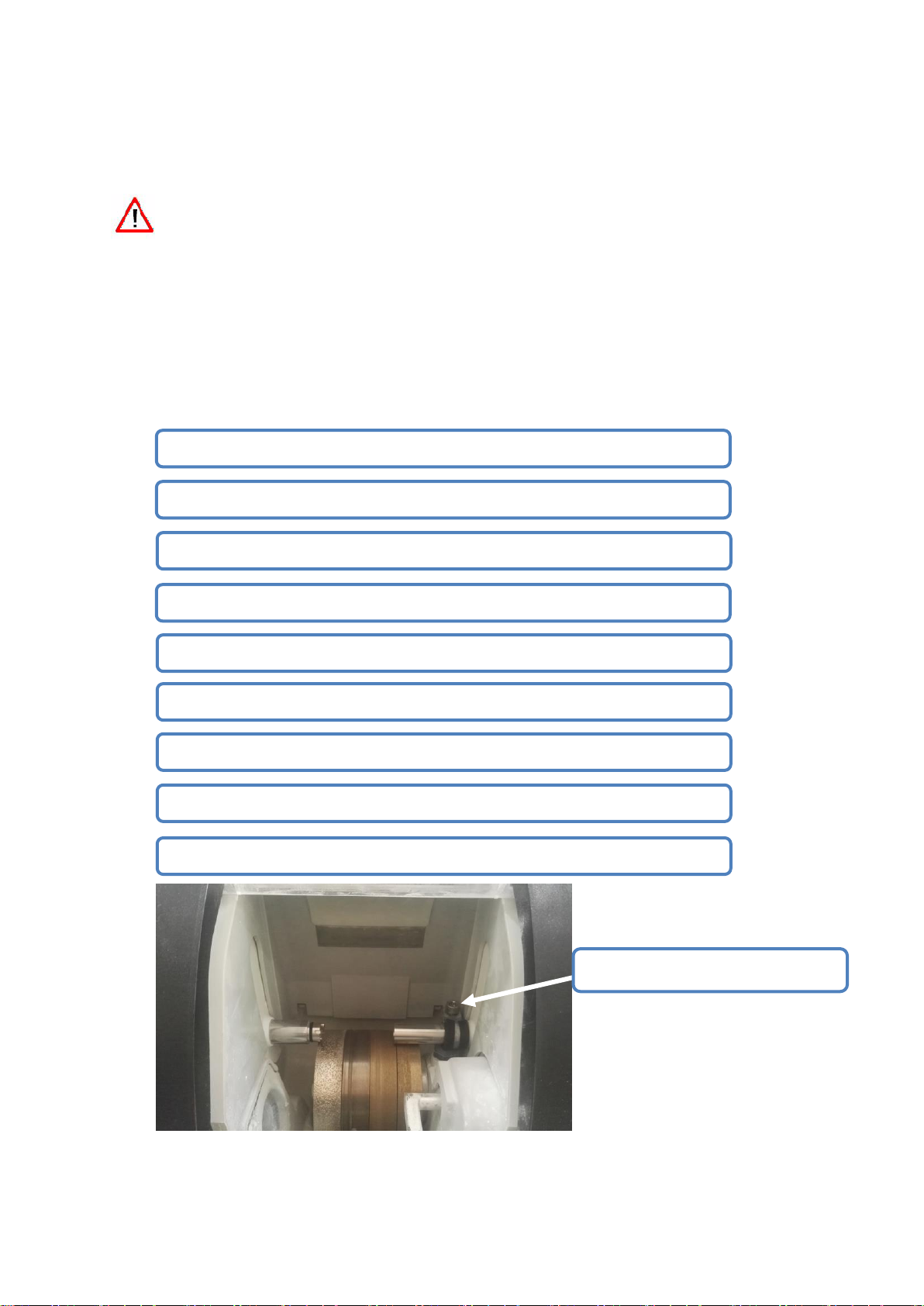
1.1 OPEN THE PACKAGING OF MACHINE
#1 At least 2 person carry edger onto the ground,
#2 Cut off the 4 packing belt outside the package,
#3 Remove the package,
#4 Check supplied parts on attached list (tool box, piper etc.),
#5 Take out protecting plastic form inside the machine,
#6 Remove 4 fixing screws at the machines transportation rails,
#7 At least 2 persons carry machine from rail to working table,
#8 Remove carriage fixing device,
#9 Keep the machine package, we suggest you keep packages flat for storage
Remove carriage fixing device
1.1.1 WARNING
> Machine must be put the same direction as mark shown on package, cannot be put upside
down.
> Put the machine on flat and stable surface.
1.1.2 PROCEDURE
OPEN THE PACKAGE AS FOLLOWING PROCEDURE:
- 6 -
Page 8
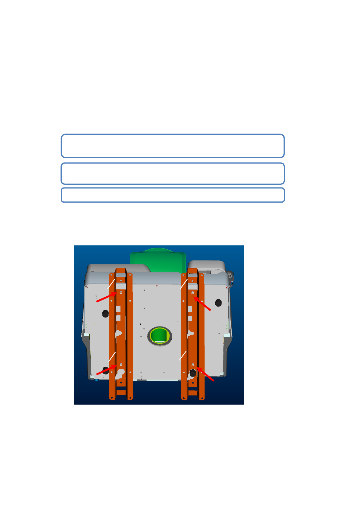
1.2 REMOVE THE FIXED TRANSPORTATION RAILS
#1 Under the help of another person,turn over the machine, so you can
find the 4 screws that used to fix the rails
#2 Use 13mm inner hexagon spanner to take off the screws, remove the
rails
#3 Keep the rails together with the other packing materials
1.2.1 CONDITION
> Put thee machine on the working table,
> Around the machine, we need enough space.
1.2.2 PROCEDURE
Remove the rails in following procedures:
As shown in below figure:
- 7 -
Page 9
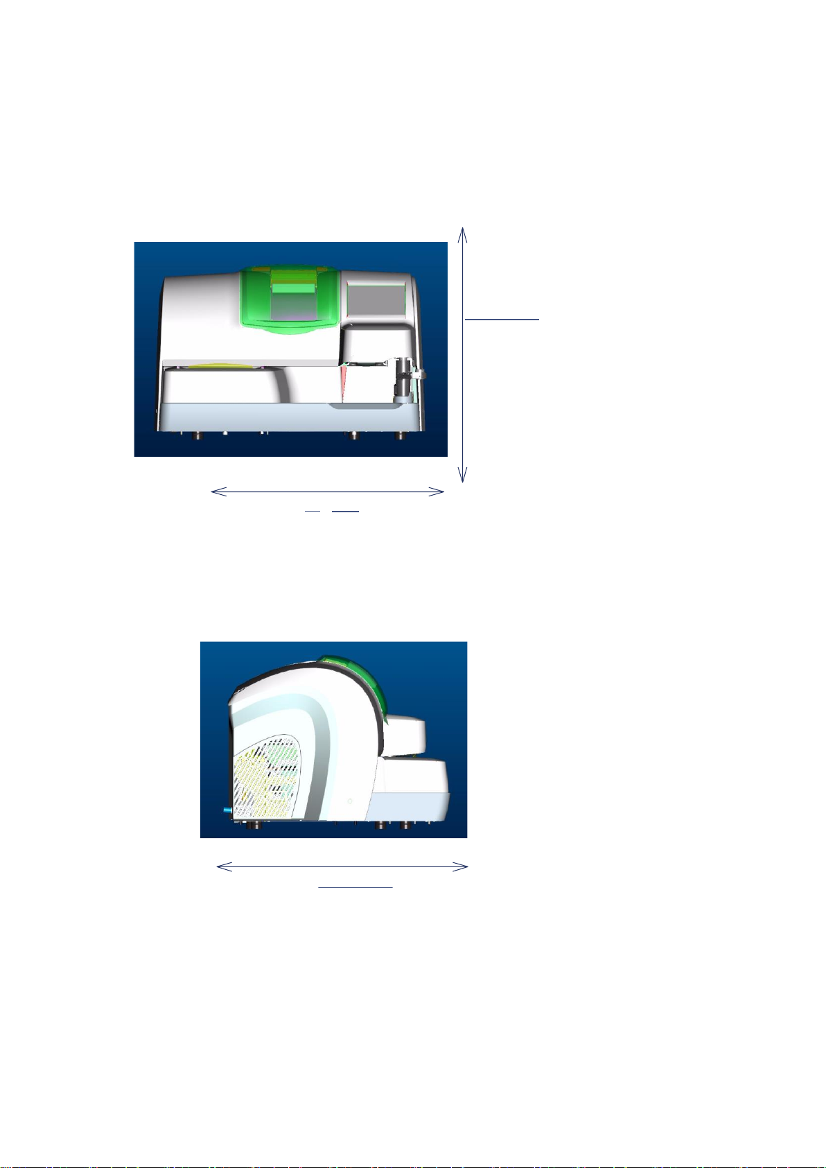
1.3 PREPARE THE WORKING TABLE
H = 442
W
728
D = 600
1.3.1 MACHINE SPECIFICATION
Machine size as below figure:
> length = 728mm
> height = 442mm
> width = 600mm
> total weight = 75kg
- 8 -
Page 10
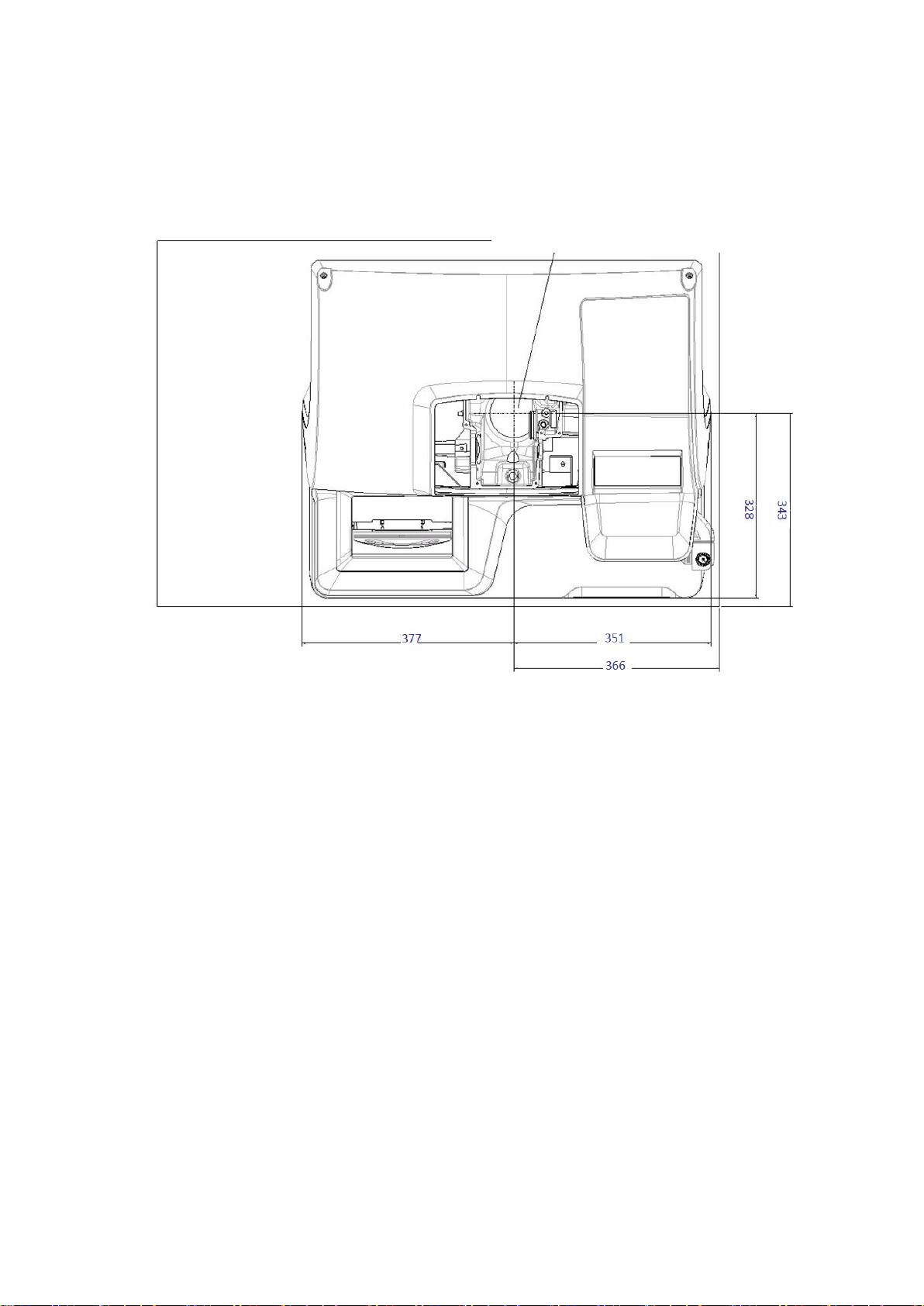
1.3.2 WORKING TABLE SIZE AND DRILLING HOLE RERQUIREMENT
Diameter of drain piper 100mm
As following figure, it shows the machine size at the table and also the drain piper hole
position. Before drilling hole, make sure the position of machine.
NOTE:
> Following size for reference:
>>Length of machine:728mm;
>>Width of machine:600mm;
>>Diameter of drain piper:100mm;
>>Distance of center of drain hole to right side of machine:351mm;
>>Distance of center of drain hole to front side of machine: 328mm;
> Leave enough space around the edger.
> Make sure the working table to be flat and stable.
> Keep machine away from the heat source.
- 9 -
Page 11
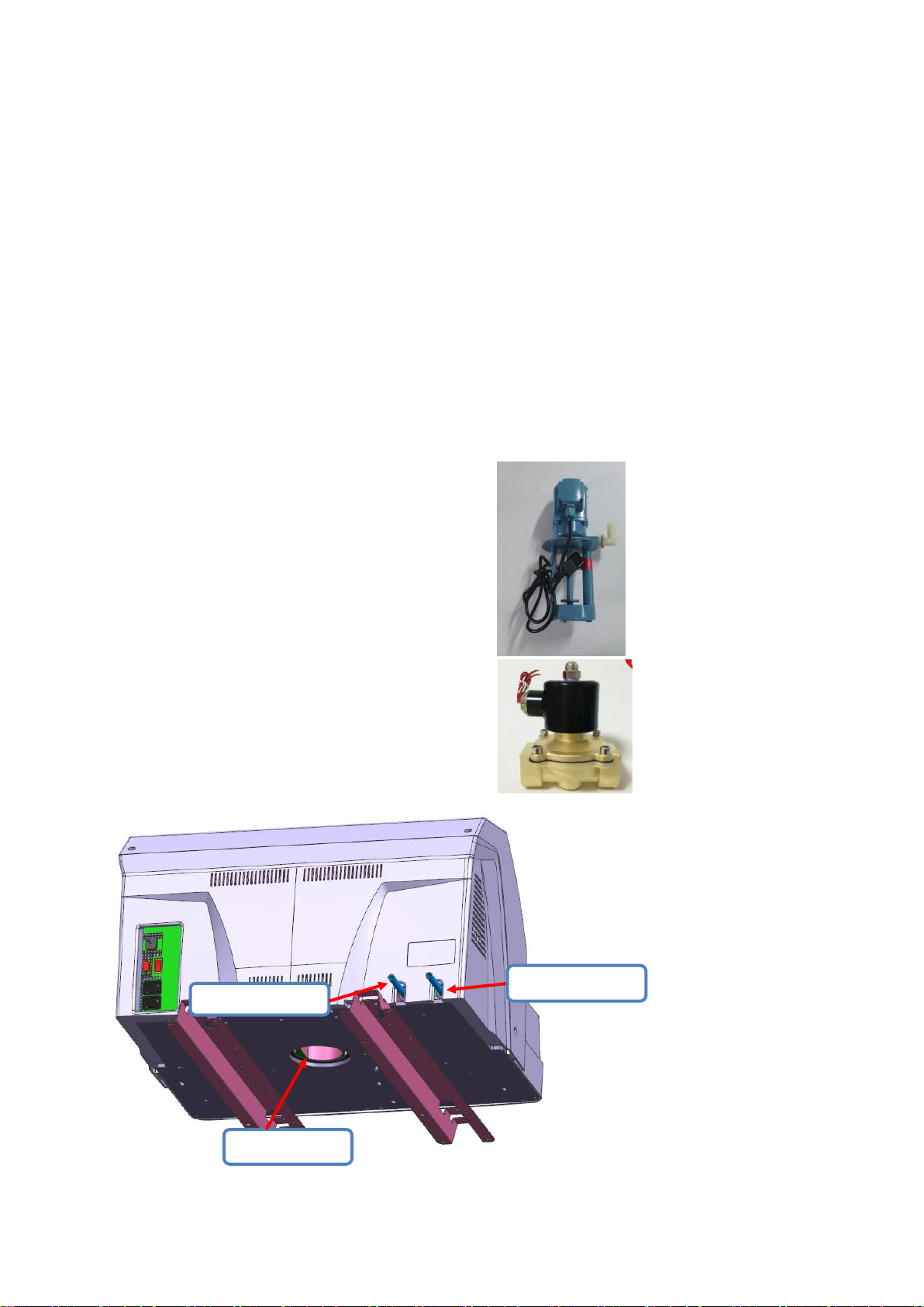
1.4 WATER SUPPLYING SYSTEM
Drain water piper
Edging front water
Edging back water
1.4.1 DESCRIPTION
1.4.1.1 General status:
> Edger must install valve to control water supply, position of valve cannot be 80cm higher than
edger. Valve must be operated easily so when stop machine, people can close water supply
anytime.
> Drain piper diameter is 100 mm. To make sure discharging all scrap, we should have at least a
5% slope.
1.4.1.2 Filter tank with water pump
> Length=500mm width=400mm height=280 mm
> Volume: 50L
1.4.1.3 Water pump
> Power = 40 W
> Flow rate = 12L/Minute
> Discharge height = 3.0m
> Voltage = 220V-230V/50Hz 110V-115V/60Hz
1.4.1.4 Magnetic valve
> Voltage = 220V-230V /50Hz 110V-115V /60Hz
> Power = 20 W
1.4.2 PIPER CONNECTIOIN
> Piper connection as below figure:
- 10 -
Page 12

1.4.2.2 Procedure
#1
#3
Connecting magnetic valve
to supply water directly
Connecting pump to use circulating
water
Pump outlet
Water quantity cannot
exceed the pump water
level
Connecting pump or magnetic valve power
As below figure
- 11 -
Page 13

Follow below steps to connect water supply piper to edger, and fix.
#1 Checking if power of machine is off, power should be cut.
#2 Checking if water supply is closed.
#3 Make sure machine is Place horizontally => regulate 4 screws
under the machine
#7 If the water supply is clogged, check the permeability of the
pipe, especially around the magnetic valve.
#4 Connect the drain piper to the bottom of machine
#5 Connect the water supply pump to running water or pump
#6 If choosing running water, then need to connect to drain piper
#8 Connect the pump or magnetic valve to power.
- 12 -
Page 14
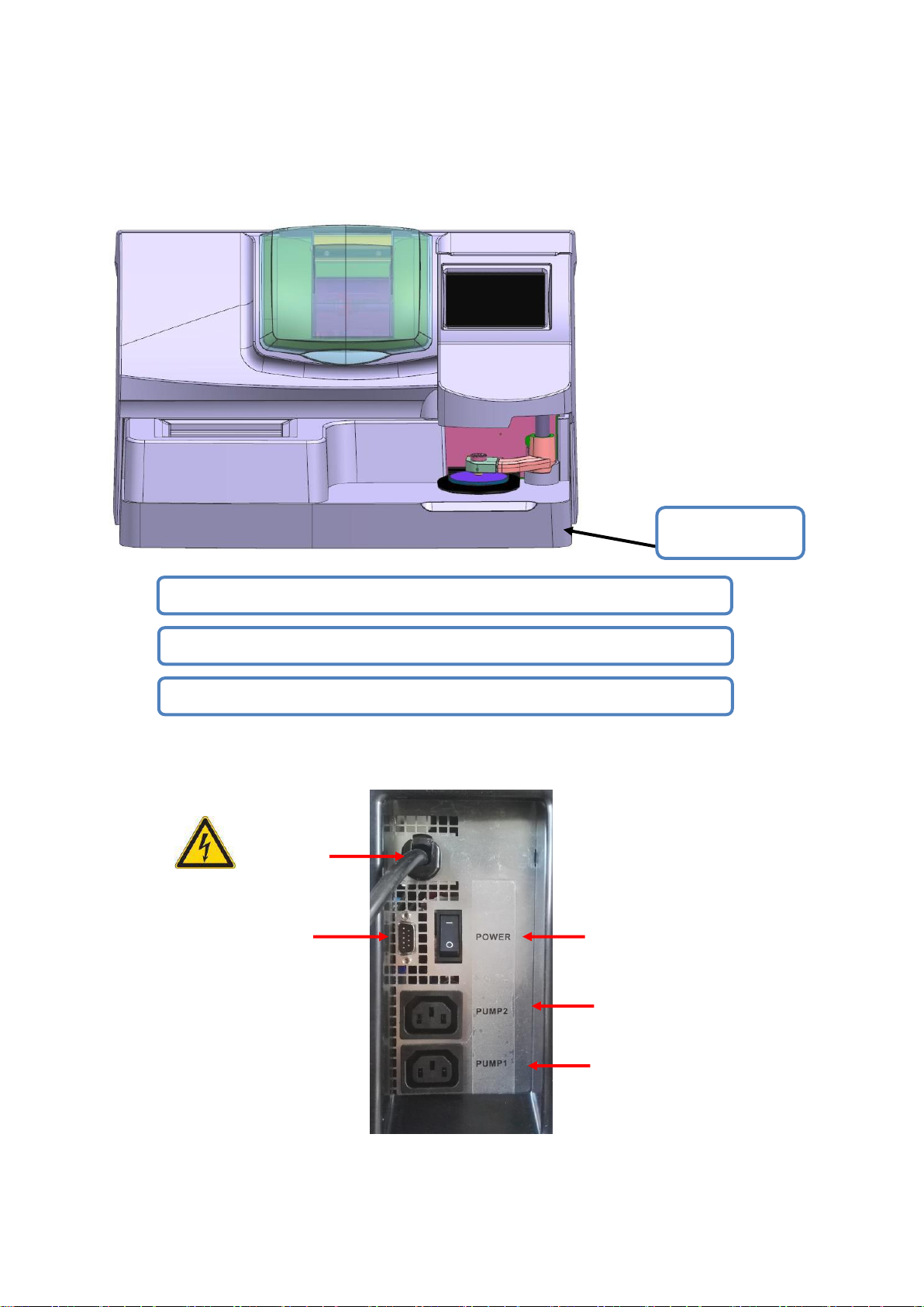
1.5 ELECTRICAL CONNECTION
Power switch
#1 Checking if power of machine is off, power should be cut.
#2 Connect scanner to RS232 port
#3Please plug in power and plug of water pump or magnetic valve.
Power line
Front water
Pump/magnetic valve
Back water
Pump/magnetic valve
Outer cover ground
wire
RS232 port
1.5.1 ELECTRICAL WIRE OF THE EDGER
>Power plug must be grounded. When assembling, outer cover must be grounded.
When connecting edger with its supporting equipment, please follow below figure:
- 13 -
Page 15
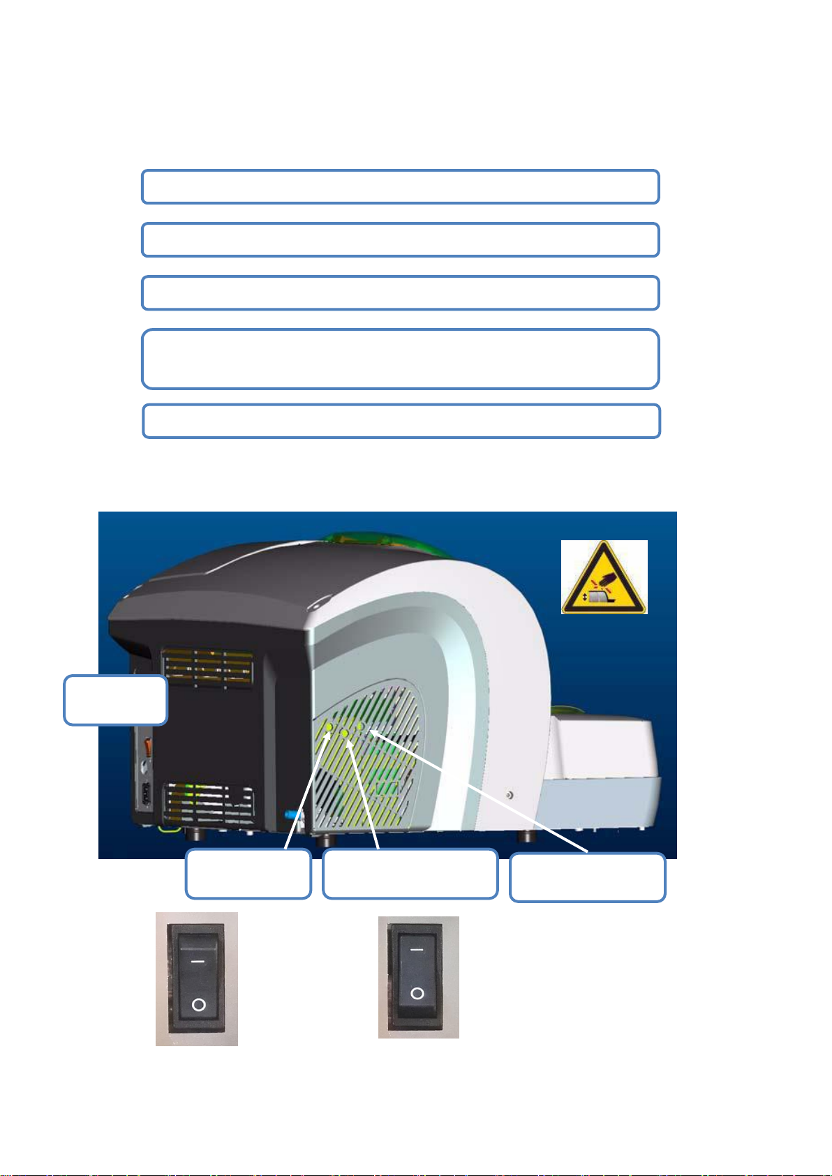
1.6 START THE EDGER
#1 Checking if power of machine is off, power should be off.
#2 Assemble the chuck and chuck seat to main axis
#3 Plug in, turn on the switch(ON/OFF switch)
#4 Simulate start, adjust left side flow regulating screw to regulate
nozzle’s flow and water quantity at edging area
#5 Obtain 1 to 2 tasks to test if machine is running regularly
PC back water
quantity regulate
Front water of wheel water
quantity regulate
Transparent water-proof
cover water regulate
Switch positon
of edger
Follow below procedure to start the edger:
Water quantity regulating at edging area, like below figure:
0:OFF 1:ON
- 14 -
Page 16

2. SAFETY PRECAUTIONS
2.1 NOTICE
2.1.1 OPERATOR
> Please read the manual carefully and put it near the edger for easy reference.
> The machine has rotating device, the wheel have potential risk, Don’t put hands near the
rotating wheels.
> Machine is heavy and need to be carried by at least 2 persons.
> When start clamping, put your hands outside of contacting area.
> Before touching the fuse, the power cord must be disconnected.
> During the installation, you must ensure that the water circuit is well sealed.
> The power plug must be unplugged before repair the edger.
2.1.2 MACHINE
> The voltage of the power supply must be in accordance with the rated voltage marked on the
label on the back of the machine. Contact the professional electricians if the voltage of the
installation site is uncertain.
> Switch located behind the machine, marked ON / OFF. Plug used to disconnect the main
power.
> When lightning or prolonged un-use, please cut off the connection with the main power
supply.
> The machine should be away from the heat sink and other heat sources which affect the
operation performance of the equipment.
> Do not obstruct and cover the vents on the carriage to ensure proper operation of the
machine.
> The machine must be installed in a well-ventilated room.
> Do not overload the socket or plug or this could cause a fire or electric shock.
> Avoid using drawn leads as power cables.
> Machine should stay away from wind and sand environment.
> Any maintenance job (need to open, close the cover) must obtain the consent of the
manufacturer or its distributor.
> Sign at different place Tips may cause the corresponding damage, should pay special
attention to.
> Controlling pump socket => electric shock hazard.
> Edging area=> physical damage.
> Water supply system => Water pressure in excess of 1 bar is dangerous.
- 15 -
Page 17

2.2 SUGGESTIONS
> Observe the equipment maintenance requirements.
> Place the power cord properly.
> All maintenance matters, please contact with the seller and professional technical personnel,
must use the appropriate accessories.
> Only online with the device specified by the vendor.
> If strictly implement the instructions in the manual, you can ensure the normal operation of its
various functions.
> The equipment must be cleaned regularly.
> Wipe the cover with a soft, damp cloth dampened with a little alcohol .
> Note: You can not use the following items when cleaning:
Liquid containing ammonia, soda or acetic acid,
Organic solvents containing acetone, benzene or chlorylene.
> Touch screen:
>> Do not force the touch screen, otherwise it will be fractured.
>> Can not use pen, scissors, pliers and other sharp objects pressure touch screen.
>> When operating the touch screen, your hands must be kept dry.
>> Clean the touch screen with a soft, clean, dry cloth.
> Edging system:
>> Before starting the edger, check if the water system is ready (valve on).
>> The water system must ensure to be sealed well.
>>If you use recycled water, the water inside the tank must be replaced regularly.
>>Periodically check the probe, if there is wear or damage, it should be promptly replaced.
>> Clean the surface of CR39 daily with water and a soft sponge or a brush to avoid
scratching the plastic surface.
>> Regularly wash the water-proof cover.
If user have not operated properly according to this manual and leads to edger problem, then
manufacturer wont be responsible for any problem.
- 16 -
Page 18
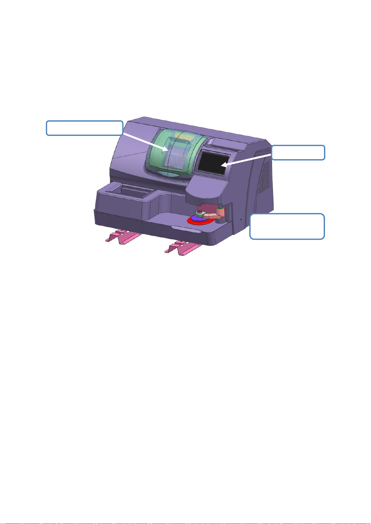
Lens edging window
Touch screen
Optical scanner/center
system
3. USE OF EDGER
3.1. APPEARANCE
3.1.1 APPEARANCE OF THE EDGER
Below figure is panorama of edger
3.1.1.1 Touch Screen
> Function of touch screen:
>> Operate ALE-1600 interface, input edging task data
>> Showing lens frame and lens shape, input edging data
3.1.1.2 Optical scanner/center system
> Function of optical scanner:
>> Automatic recognize lens pattern, confirm the pattern size data
> Function of center system
>> Manually fix the center for dotted normal lens, bi-focal and progressive lens.
3.1.1.3 Lens edging window
> Function of the edger:
>> Edging the lens according to data of lens material,shape,degree etc.
- 17 -
Page 19
3.2 INTRODUCTION OF OPERATE INTERFACE
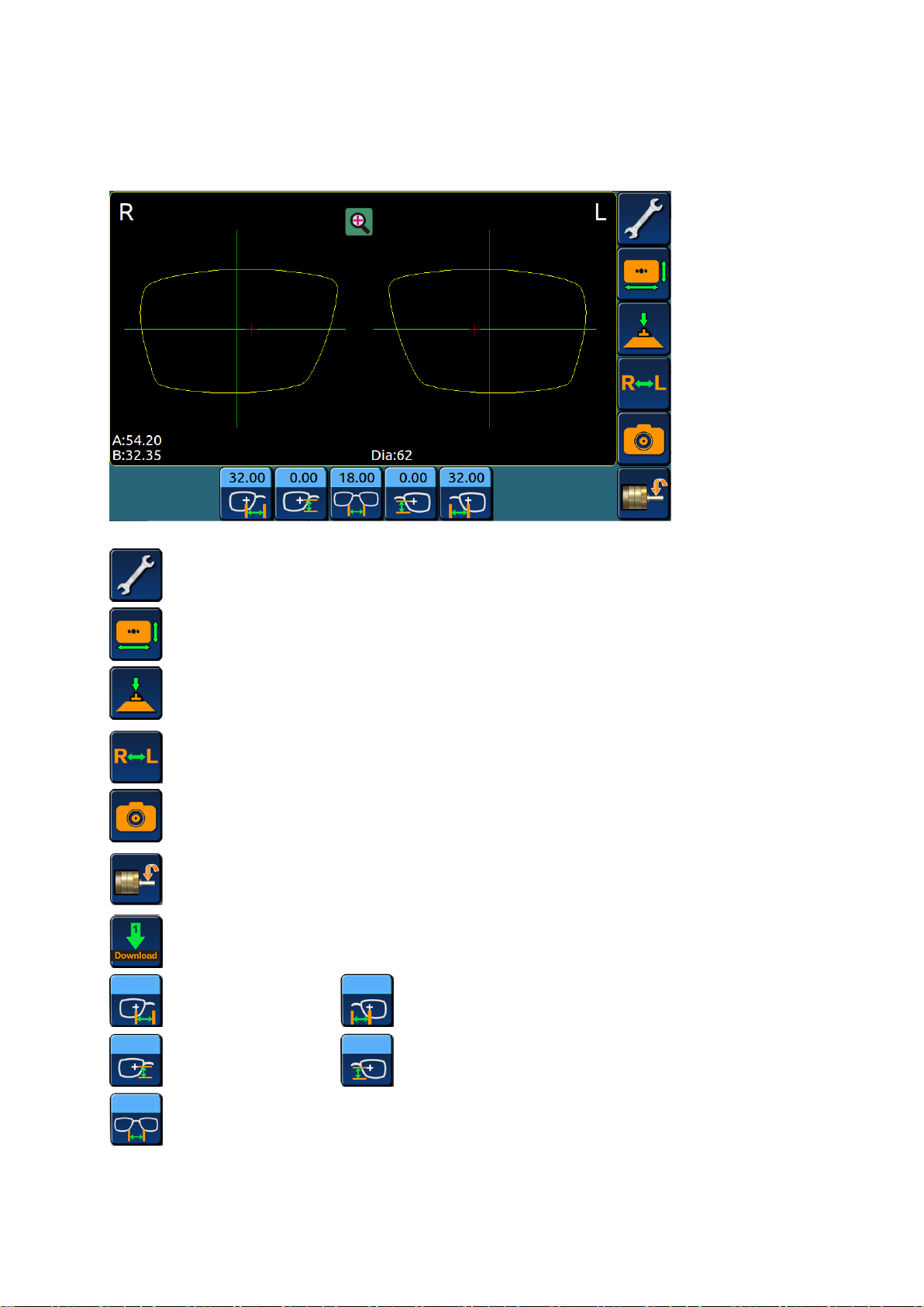
3.2.1DISPLAY INTERFACE
>>Menu interface;
>>Enter data change interface, can change shape of lens;
>>Enter optical center system, decide center of lens;
>>Mirror display of left and right eye data;
>>Enter optical scanner system, scan size of lens pattern;
>>Enter lens edging interface;
>>Obtain and display data of lens which is to be edged;
>>Input right eye PD; >>Input left eye PD;
>>Input right eye PH; >>Input left eye PH;
>>Input DBL;
- 18 -
Page 20
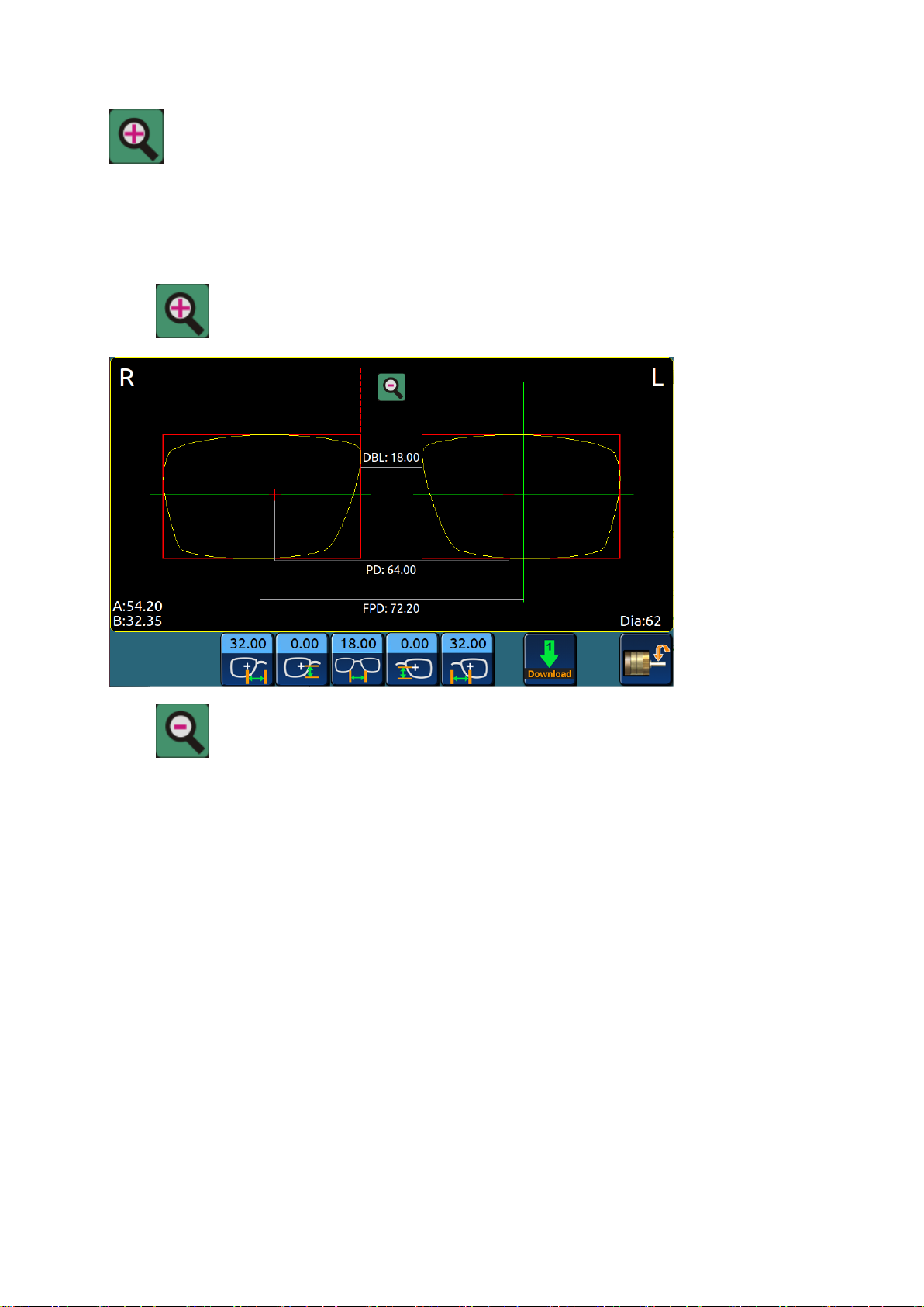
>>Enter 1:1 display interface:
Dia >>Minimum Diameter of raw lens required to edging present lens;
3.2.2 SCREEN 1:1DISPLAY
>Click on screen, enter lens frame 1:1 display screen.
>Click , go back to main menu.
>>DBL:Nasal distance of lens frame;
>>PD: Pupil distance of eyes;
>>FPD:Geometry center distance of lens frame;
>>Dia:Minimum Diameter of raw lens required to edging present lens;
>>A: Maximum width of lens pattern;
>>B: Maximum height of lens pattern;
- 19 -
Page 21
3.2.3 OPTICAL SCANNER SYSTEM
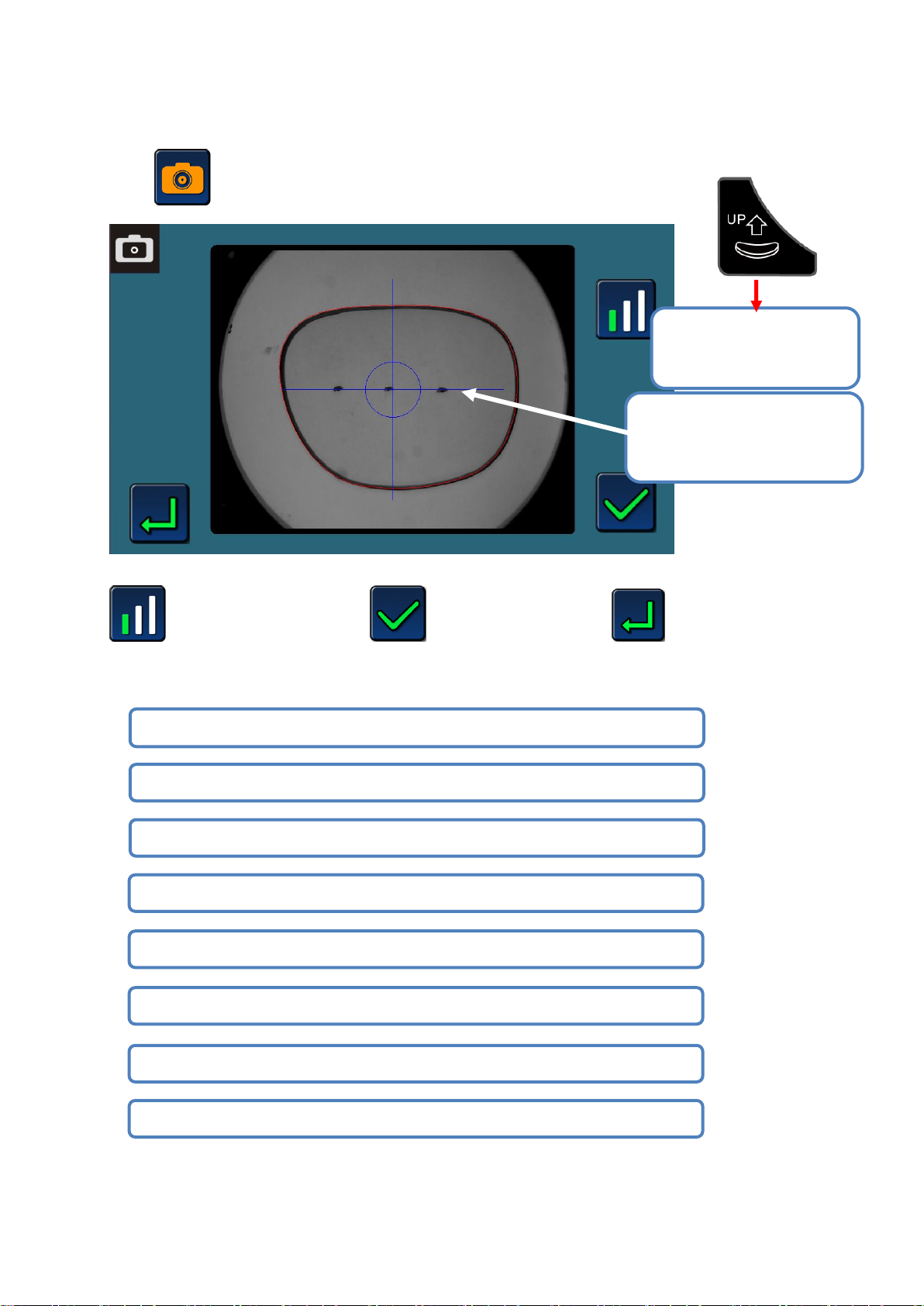
#1 Using lens meter to dot on lens pattern
#3 Convex side of pattern down, concave side up
#2 Clean the object stage, cannot have any dust or dirt when scanning
#4 Dots position coincide with the horizontal line of blue cross
#5 System will recognize lens frame data and show in red line
#6 After confirm scanned data, input DBL of lens frame
#4.Dots position coincide
with the horizontal line of
blue cross
#7 Input PD data
#8 Input PH data
#3. Convex side of
pattern down, concave
side up
>Click icon, enter optical scanner system.
>>CCD brightness control >>scanned data confirm >>return back
Operation of lens pattern scan:
- 20 -
Page 22
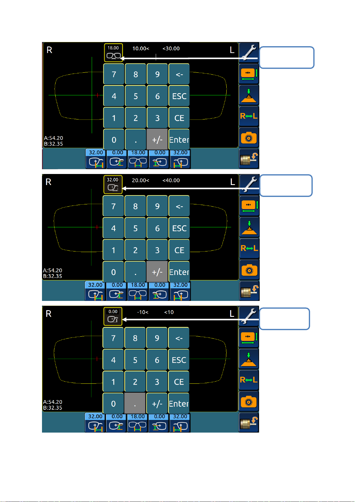
#6 DBL of lens
frame
#7 Input PD
data
#8 Input PH
data
- 21 -
Page 23
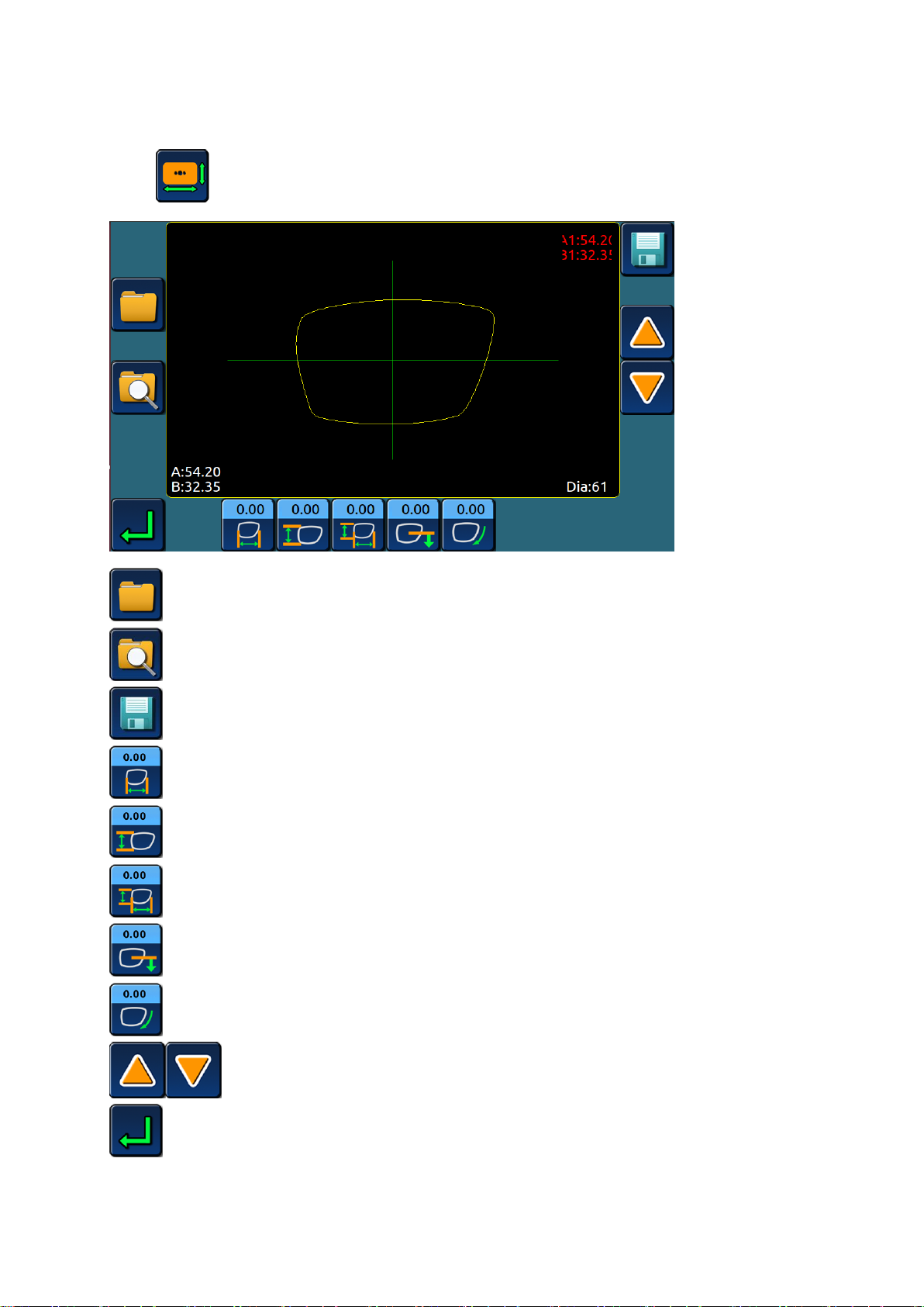
3.2.4 CHANGE SHAPE OF PATTERN DATA
>Click icon, enter pattern data change shape interface,
>>Obtain existing pattern data from internal storage;
>>Search for pattern data from internal storage;
>>Save present pattern data into internal storage;
>>Height of pattern don’t change, width change;
>>Width of pattern don’t change, height change;
>>Width and height of pattern change;
>>Shape of pattern bottom side change;
>>Pattern data rotate;
>>Pattern data angle rotate;
>>Return back.
- 22 -
Page 24
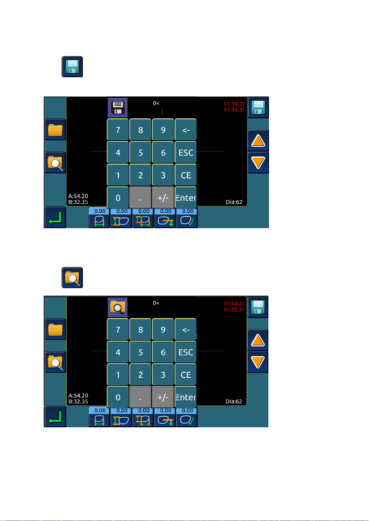
3.2.4.1 Save pattern data
>Click icon, the system will pop up a save window, input pattern number, like below
figure.
>Click “enter” button, system will save present pattern data automatically.
3.2.4.2 Search for pattern data
>Click icon, the system will pop up the search window, like below figure.
>Input the number of pattern you want to search, press “enter” icon, system will search for
pattern data automatically.
- 23 -
Page 25
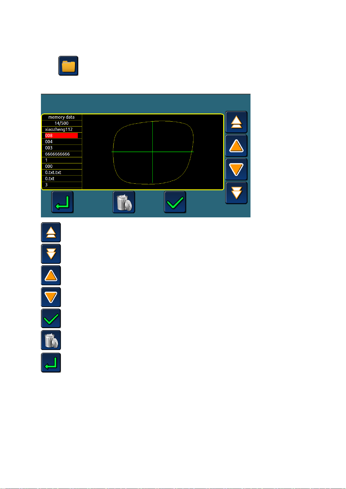
3.2.5 PICK UP STORED DATA
>Click on the shape change interface,enter the template data retrieval interface, the
memory data list will be showed
>>Display previous page data;
>>Display next page data;
>>Display the previous data;
>>Display the next data;
>>Retrieve the current data;
>>Delete memory data;
>>Return.
- 24 -
Page 26
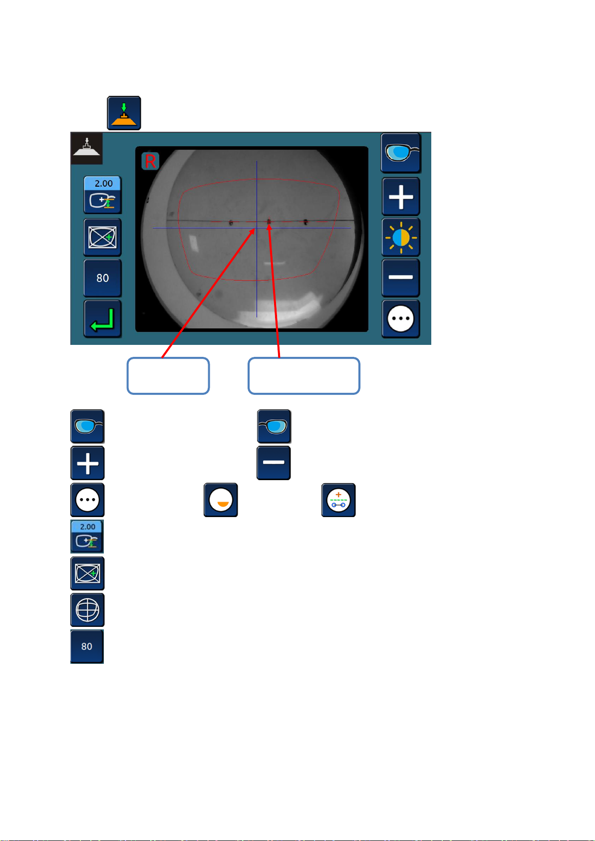
3.2.6 FIX CENTER OF LENS, PUT THE SUCTION CUP ON LENS
Optical
center mode
Geometry
center mode
>Press icon, enter the optical center interface.
>>right eye >>left eye
>>CCD increase brillance >>CCD decrease brillance
>>normal mode >>bifocus mode >>progressive mode
>>PD setting
>>geometry center mode
>>optical center mode
>>initial diameter of lens
- 25 -
Page 27
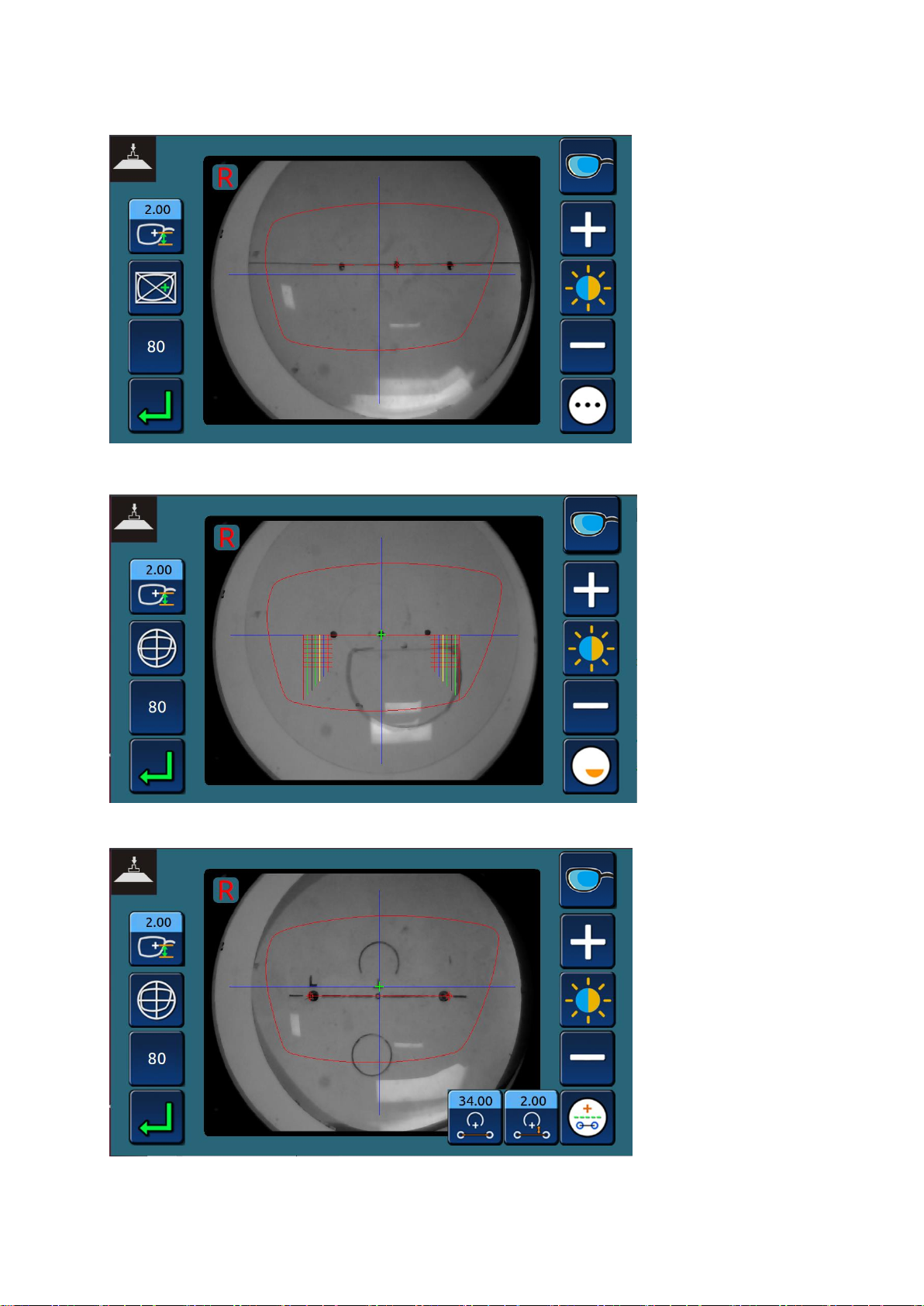
>Single focus lens fix center
>Bifocus lens fix center
>Progressive lens fix center
- 26 -
Page 28
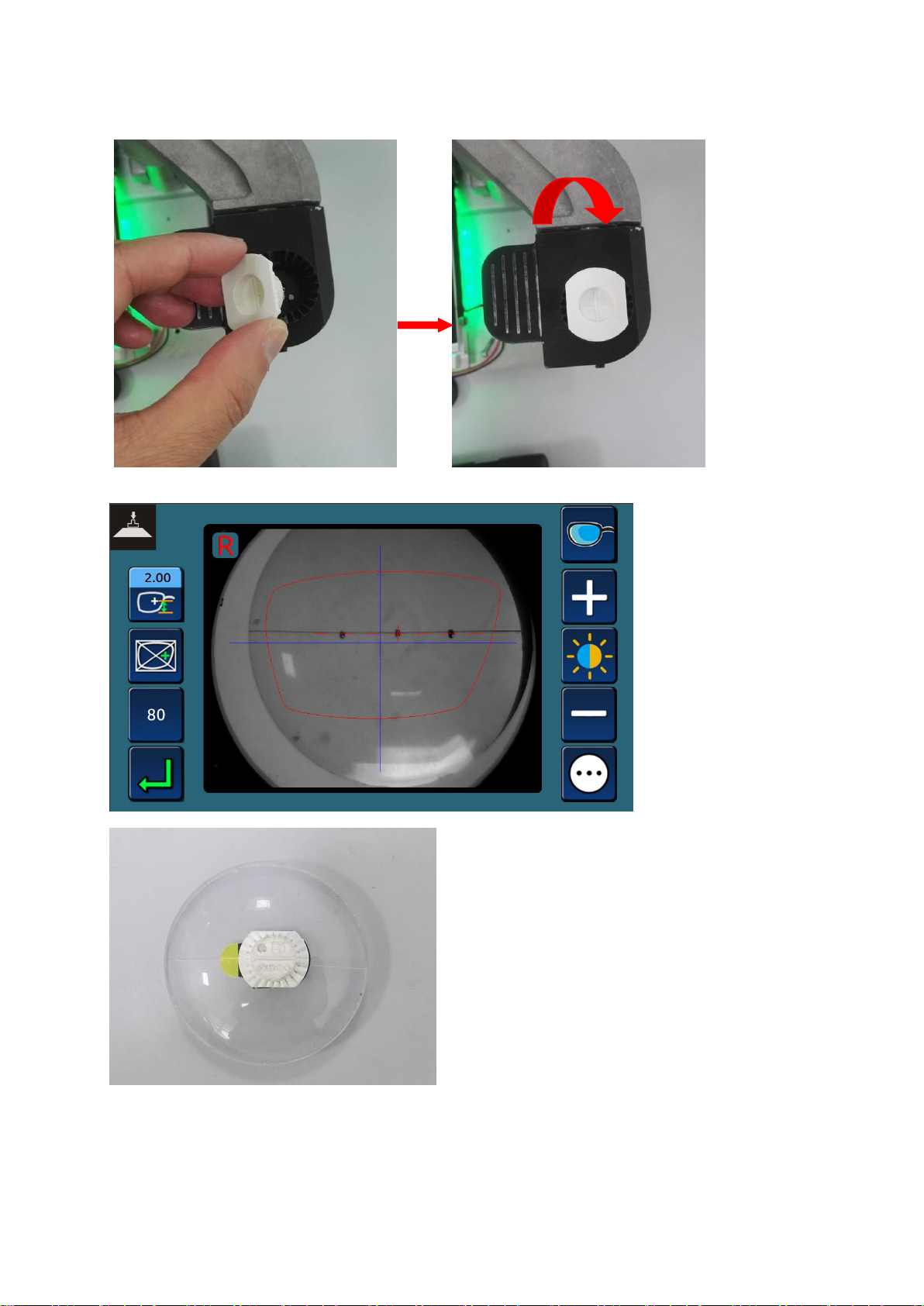
>Insert suction cup, overturn the seat
> Choosing geometry or optical center mode, rotate the arm, press the suction cup.
- 27 -
Page 29
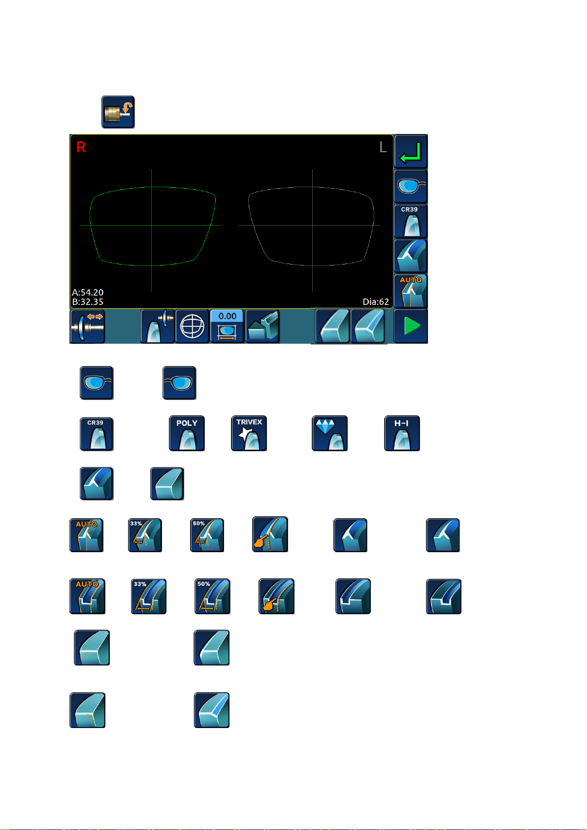
3.2.7 EDGING LENS INTERFACE
>Press icon, enter the edging lens setting interface.
1. Left and right eye processing options:
>>right eye >>left eye
2. lens material options:
>> Resin lens >>PC >> TRIVEX >> glass >> HR
3. edge shape options:
>>bevel >>flat
4.Sharp edge rate:
>>auto >>33% >>50% >>manual >>front surface >>back surface
5.Grooving rate(only apply to edger with grooving function;):
>>auto >>33% >>50% >>manual >>front surface >>back surface
6.Front side safe chamfering(only apply to edger with safe chamfering function):
>> no safe chamfering >> front side safe chamfering
7. Backside safe chamfering(only apply to edger with safe chamfering function):
>> no safe chamfering >> backside safe chamfering(small)
- 28 -
Page 30
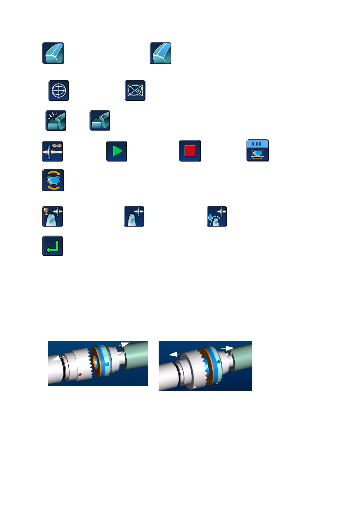
>> backside safe chamfering(middle) >> backside safe chamfering(large)
19 mm diameter adaptors
25 mm diameter adaptors
19mm small clamp
25mm big clamp
8.Lens processing mode:
>>Optical Center mode >>Geometric center mode
9.Polishing choice:
>>polish >>not polish
10.Others:
>>unlock the lens >>start to proceeding >>stop proceeding >>proceeding size
>> retouch
11.Clamping pressure:
>>(level one)Fragile lens >>(level two)normal lens >>(level three)slippery lens
>>return
3.3 LENS PROCESSING
3.3.1 CLAMP/REMOVE THE LENSES
> Clamp the lens into grinding window
After all the grinding data is entered, clamp the lens;
Each kind of lens should choose appropriate clamp
The warning information will display if the processed lenses needs special clamp,as the following
figure:
- 29 -
Page 31
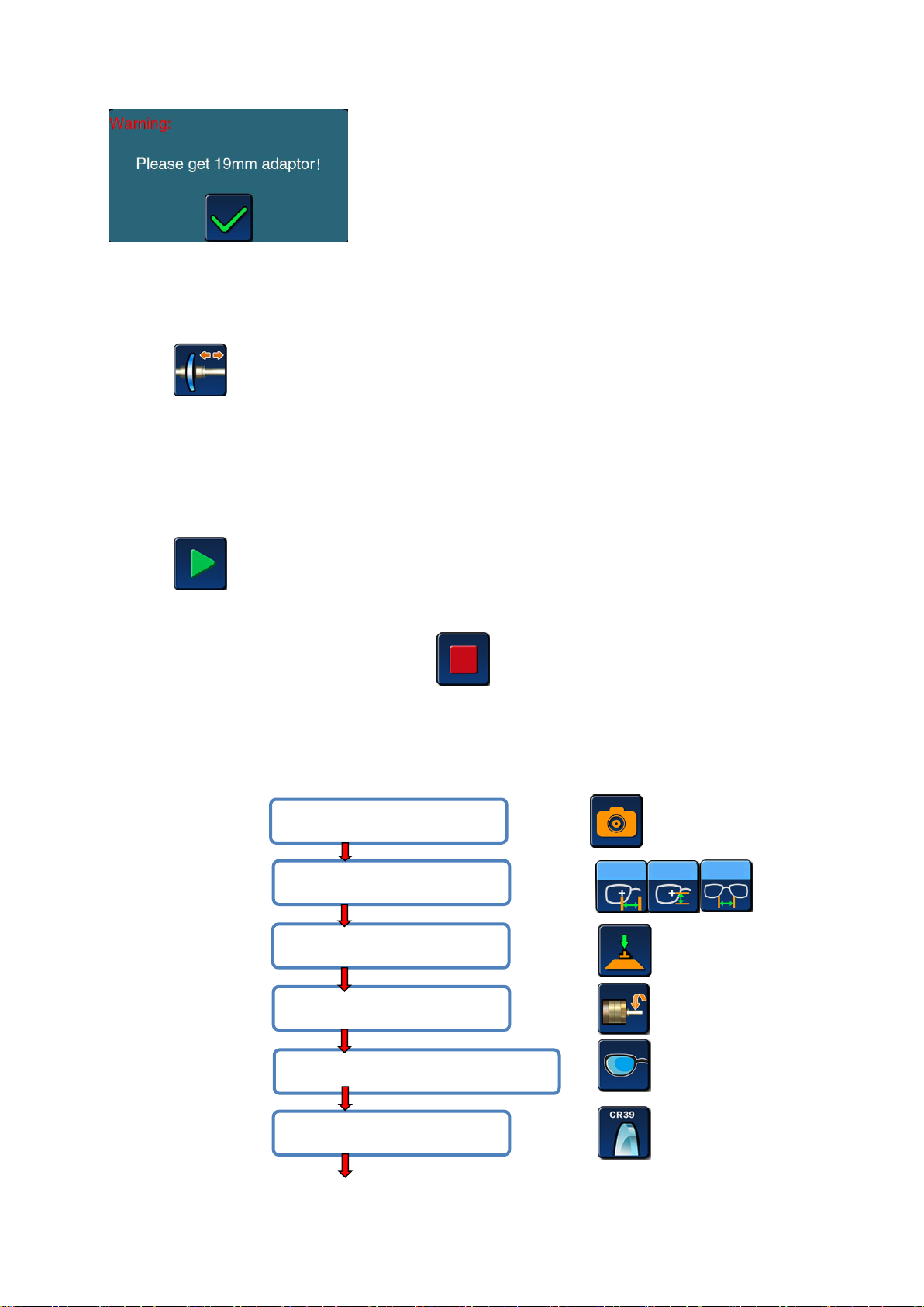
Warning: please install 19mm small clamp
#5 Select lens for left eye or right eye;
#6 Select lens material;
#4 Enter edging setting menu;
#2 Input PH, PD, DBL;
#1 Scan the pattern shape;
#3 Lens center mode selection;
> REMOVE THE LENS FROM THE GRINDING WINDOW
Open the water-proof cover after the machine stops or breaks.
Press icon, clamp will open automatically.
Taking out lens, don’t take off the suction cup, in case of modifying.
3.3.2 START/STOP THE GRINDING PROCEDURE
> STAT EDGING PROCEDURE:
After enter all data of grinding and put lens into clamp,
press icon
> STOP EDGING PROCEDURE
If you want to stop the procedure, press icon. When the grinding is processing, this
key can be transferred from another key.
3.3.3 LENS PROCESSING STEPS
> Full frame lens processing
- 30 -
Page 32
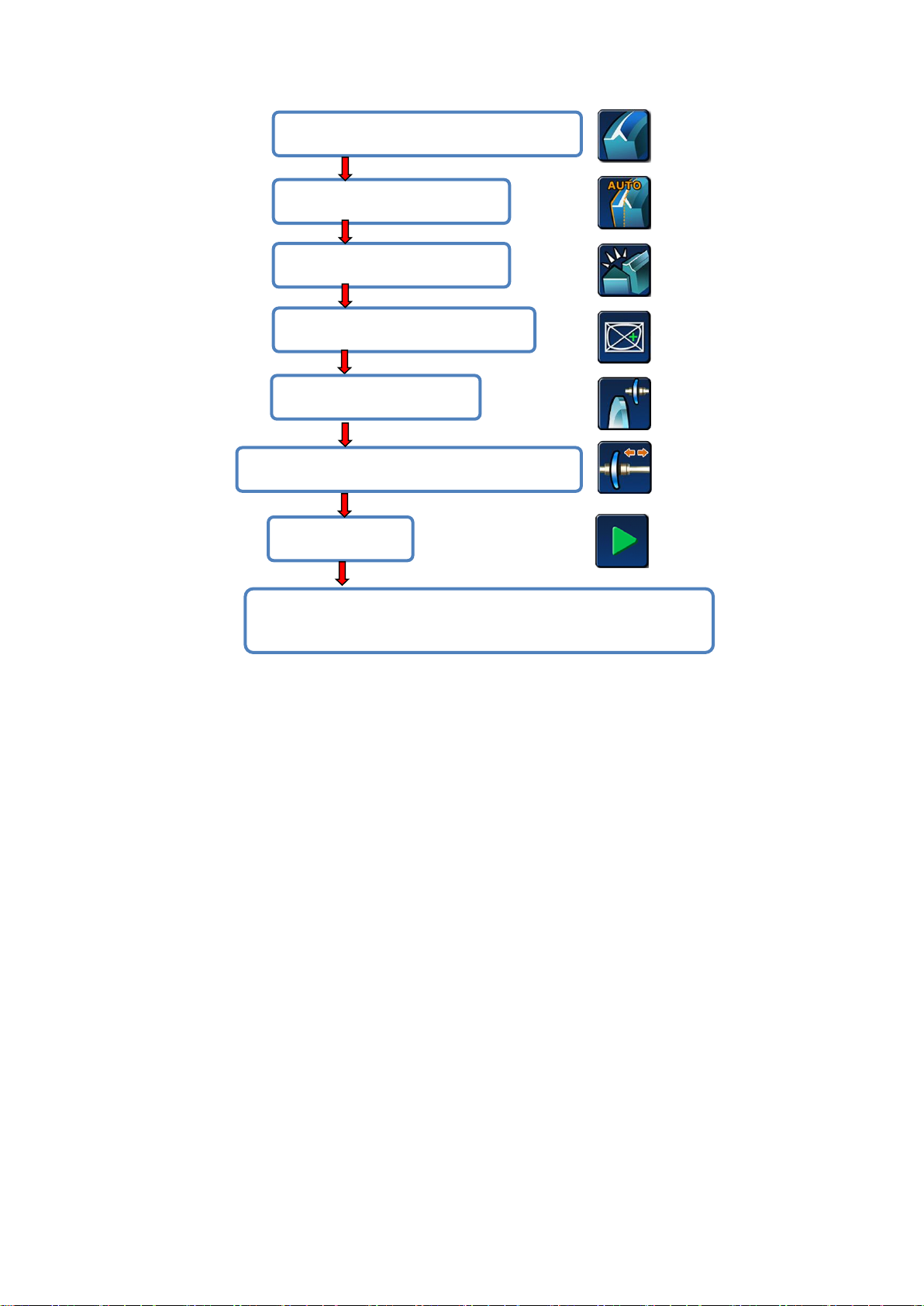
#7 Select lens fine grinding pattern(bevel)
#8 Select bevel ratio;
#9 Select polishing or not;
#10 Select lens processing mode;
#12 After blocking, put the lens in and clamp;
#13 Start;
#14 Open the window, remove the shaft and take the lens after
it’s done.
#11 Select clip pressure;
> Automatic bevel
The tip vertex position is automatically located 1/3 of the front of the lens.
>33% bevel
The apex of the tip is located about 33 percent above the front of the lens.
> 50% bevel
The apex of the tip is located at 50% of the front surface of the lens.
> Front bevel
The tip vertex position is located on the front surface.
> Back bevel
The apex of the tip is located on the back surface.
IMPORTANT NOTE:
> If the maximum thickness of the lens is less than 2mm, the position of the bevel/slot will be
automatically located at half of the lens.
- 31 -
Page 33
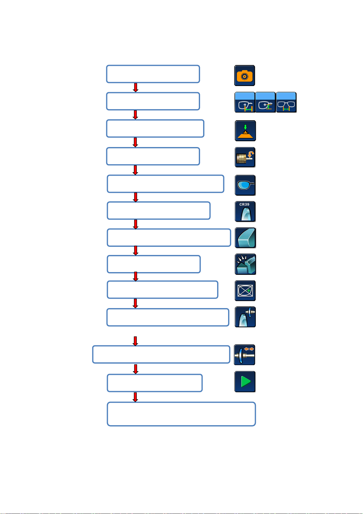
> Half - frame or rimless lens processing
#5 Select lens for left eye or right eye;
#6 Select lens material;
#7 Select lens fine grinding pattern(flat);
#8 Select polish or not;
#9 Select lens processing mode;
#11 After blocking, put the lens in and clamp;
#12 Start;
#13 Open the window, remove the shaft and take
the lens after it’s done;
#10 Select clip pressure;
#4 Enter edging setting menu;
#2 Input PH, PD, DBL;
#3 Lens center mode selection;
#1 Scan the pattern shape;
- 32 -
Page 34
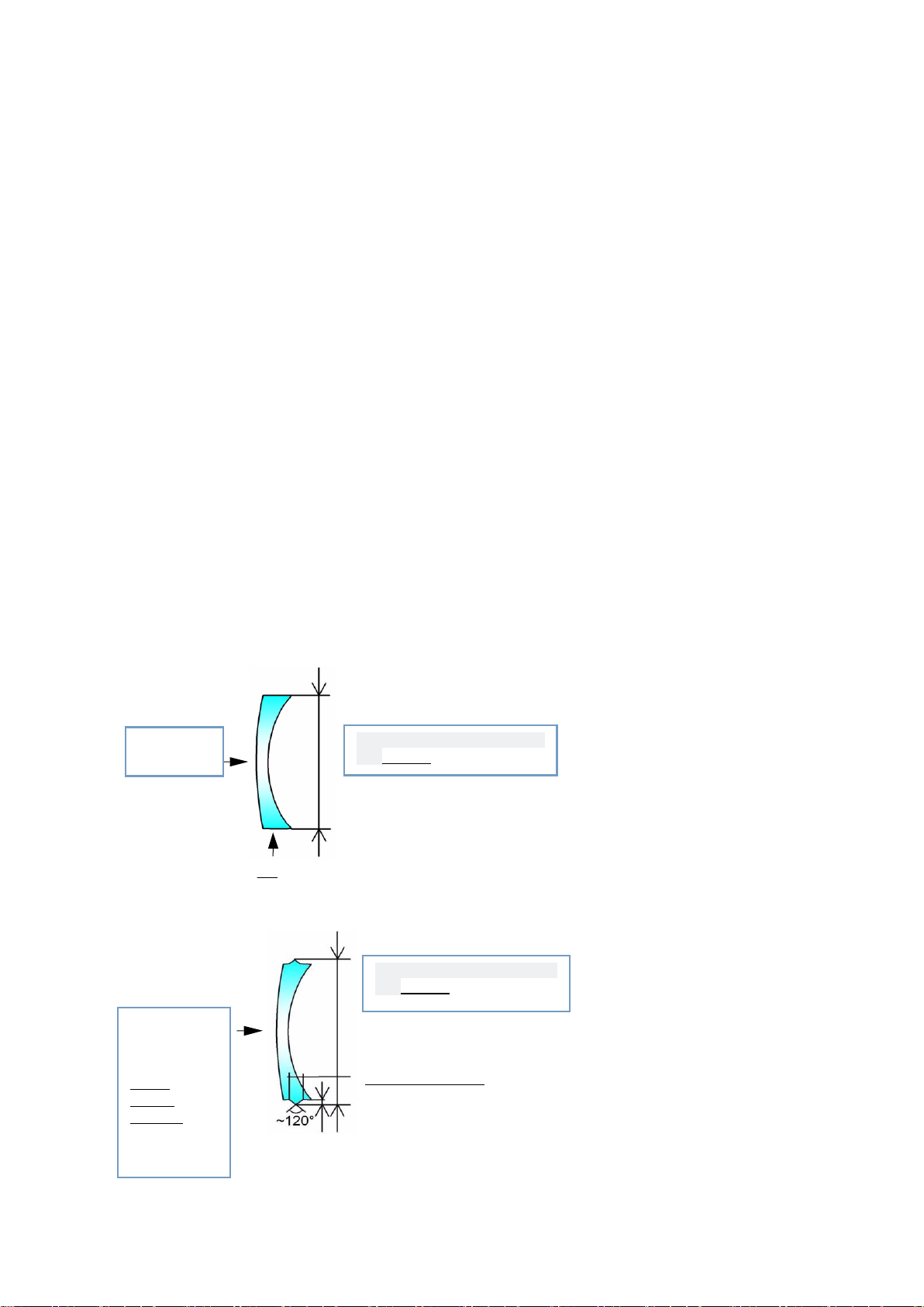
3.3.4 PROCESSING RANGE
Bevel width=2.8mm
Flat
Front
surface
Minimum height of finished
lens=19mm
Front surface
Bevel
Height
=0.8mm
Minimum height of finished
lens=19mm
> Lens
Diameter:Unprocessed lenses, with a diameter of 80mm and 10mm offset, that is to say, the
maximum diameter of 100mm without offset lenses.
Thickness:
maximum thickness of resin lens:18mm
maximum thickness of glass lenses:16mm
Lens minimum center thickness:1.2mm
Completed rough lens, the maximum thickness of the flat side:11mm
Completed rough lens, the maximum thickness of the edge of the glass:15mm
Completed rough lens, the maximum thickness of the resin tip:15mm
> Shape
The minimum height of the flat:19.00mm
The minimum height of bevel:19.00mm
> Machining range diagram
>> Flat lens
>>Bevel lens
- 33 -
Page 35
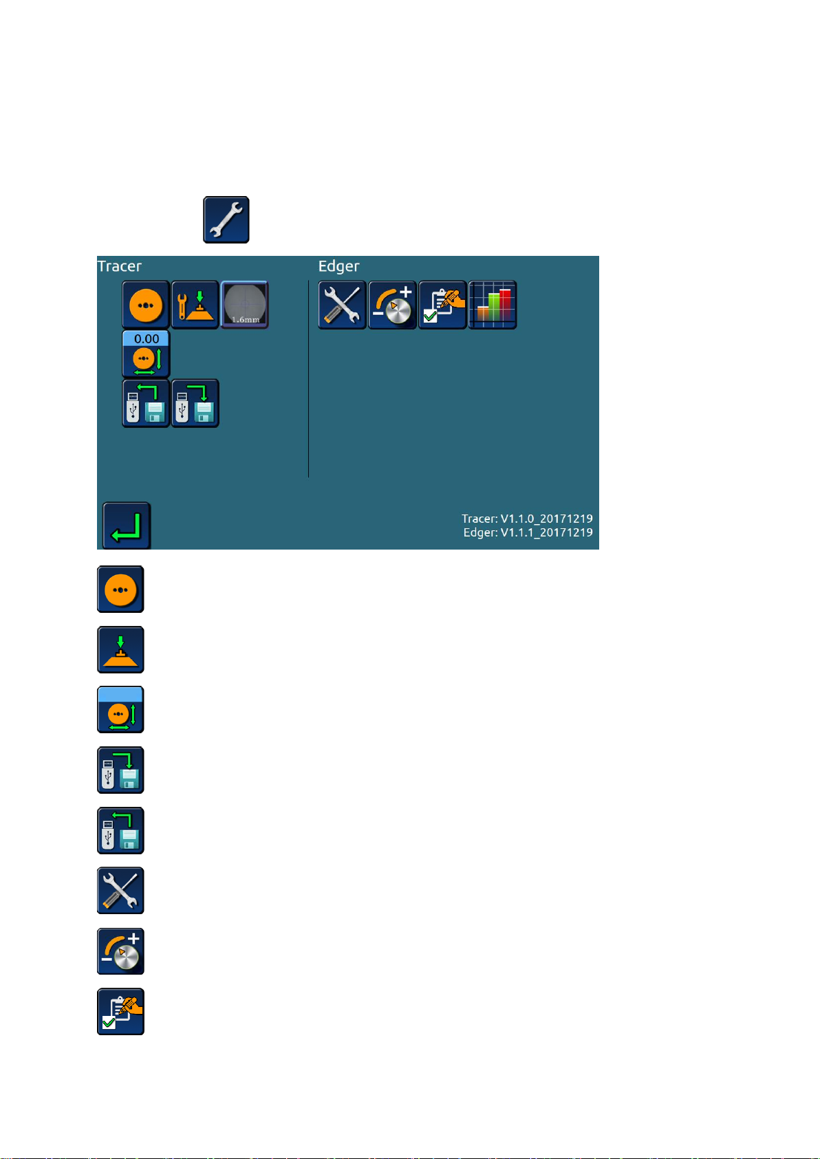
4. CONFIGURATION MENU
4.1 CONFIGURATION MENU INTRODUCTION
4.1.1 SYSTEM MENU INTERFACE
> Click the icon on the main interface,Enter menu password,Enter the menu.
>>Calibrate size of scanner;
>>Calibrate of optical blocker;
>>Offset the scanning size;
>> Memory data export;
>> Memory data import;
>> The whole machine test;
>> The machine set;
>> Initial settings;
- 34 -
Page 36
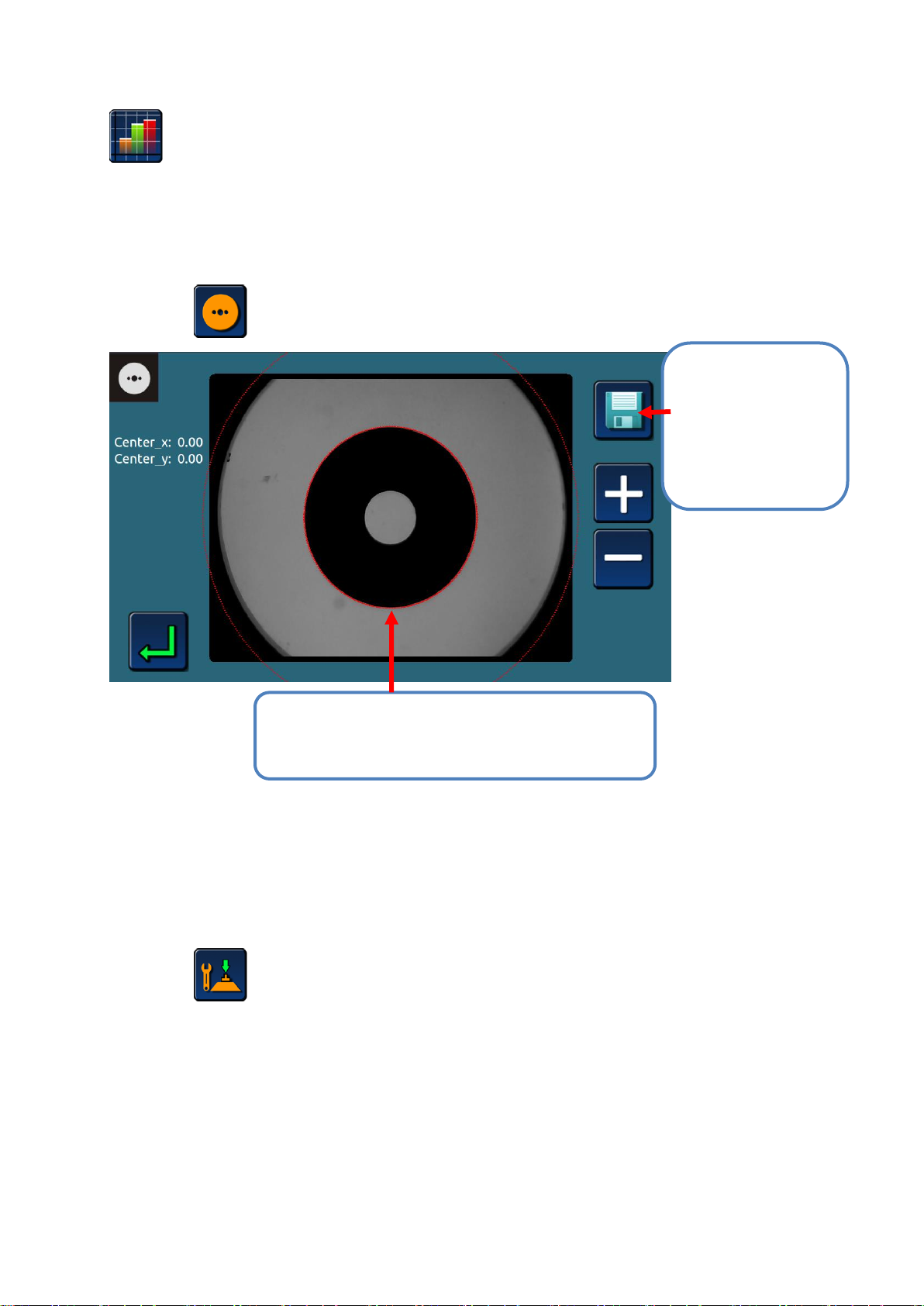
>> Processing statistics table;
#1 Move the calibration plate, press + - icon,
regulate the red circle to coincide with calibration
plate.
#2 Red circle
coincide with the
calibration plate,
press “save”,
system will calibrate
size automatically.
4.1.2 CALIBRATE SIZE OF SCANNER
>Press icon ,enter scanner size calibration interface.
4.1.3 OPTICAL BLOCKER CALIBRATION
>Press icon enter blocker calibration interface;
>Taking the calibration tool, insert into suction seat, rotate the arm of blocker, pressing down;
- 35 -
Page 37
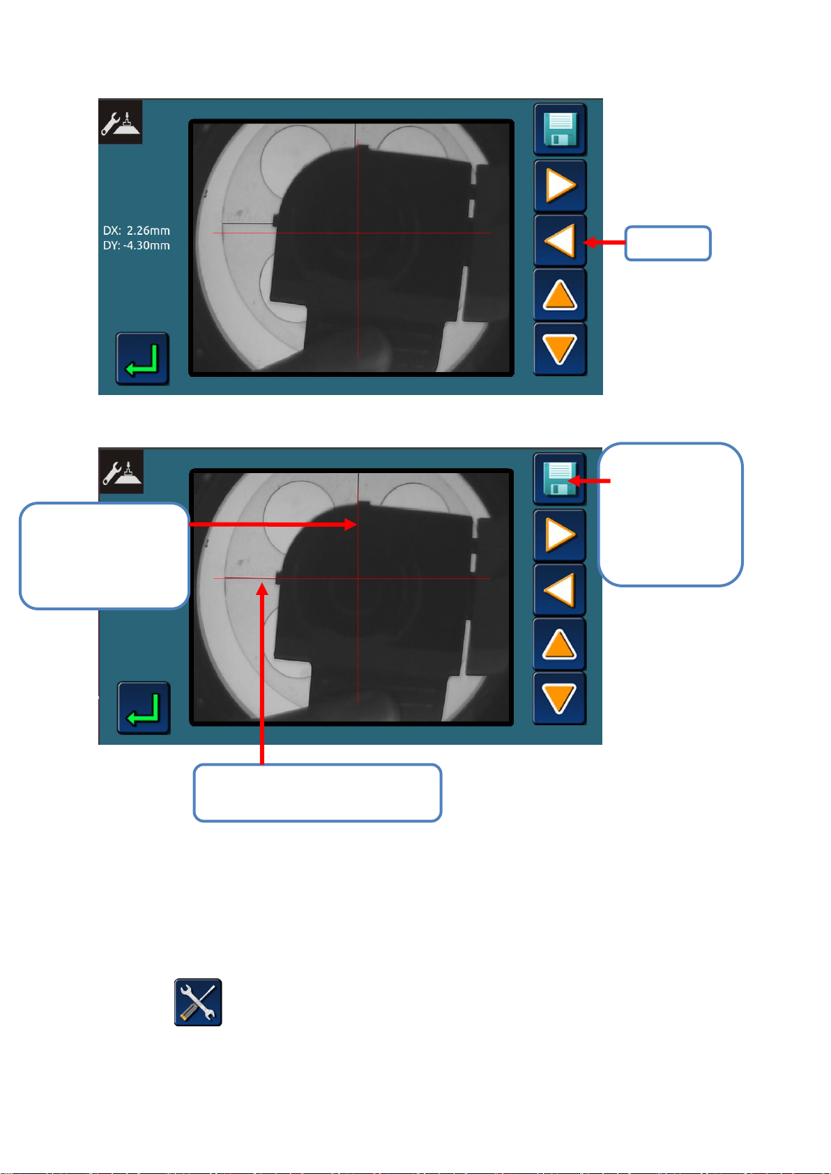
Adjust
#1. Adjust vertical
red line to be
coincide with black
line.
#2. Adjust horizontal red line to
be coincide with black line.
#3. Horizontal
and vertical red
lines to be
coincide with
black line, press
save icon.
>Adjust horizontal and vertical red line to coincide with black line, press save icon;
4.1.4 THE TEST MENU
>Press icon ,enter the whole machine test menu.
- 36 -
Page 38
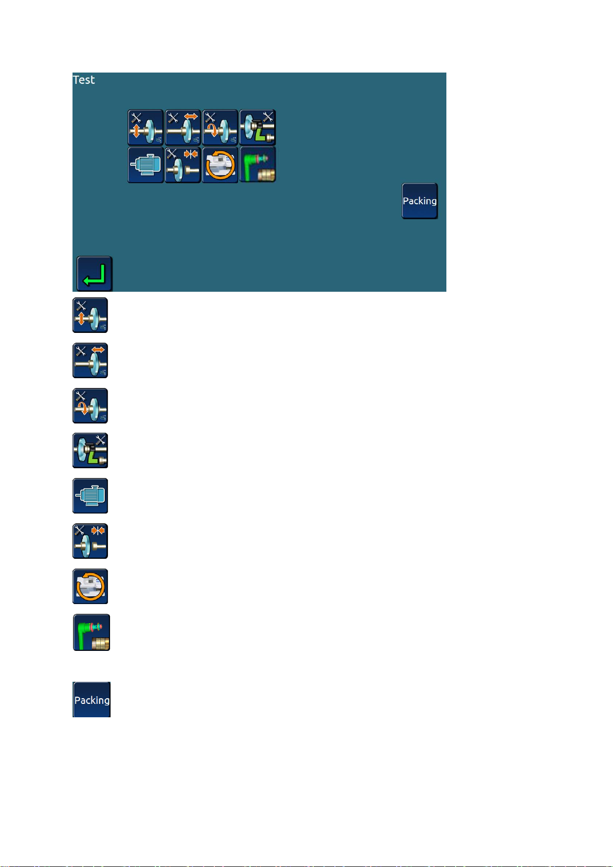
>> The performance test of the machine head lift motor and encoder;
>> Machine head horizontal moving motor, encoder performance test;
>> Performance test of lens rotary motor and encoder;
>> Scan probe component performance test;
>> Performance test of main motor and sprinkler system;
>> Performance test of clamp/loose system;
>> Machine test;
>>Performance test of grooving and safe chamfering function(only apply to edger
with grooving and safe chamfering function);
>> Lock the carriage head, pack the whole machine for transportation。
- 37 -
Page 39
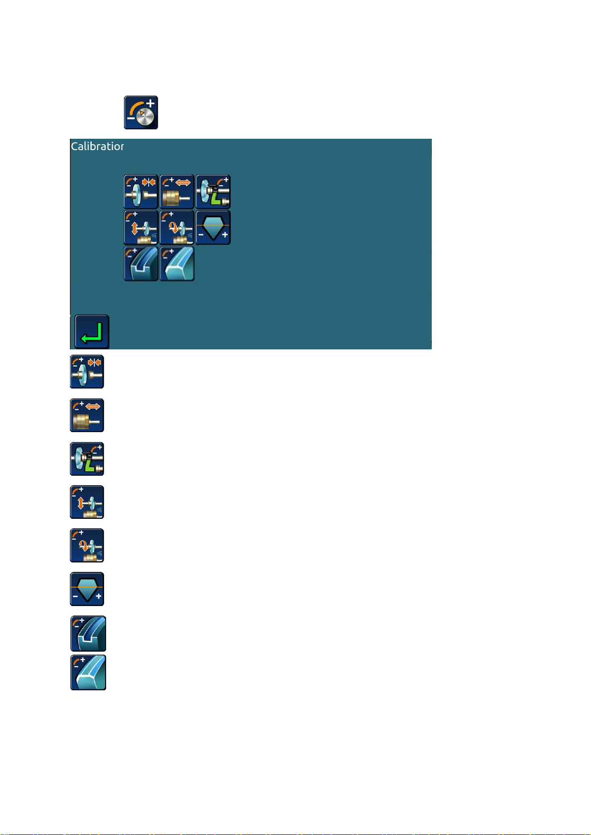
4.1.5 SETTING MENU
>Press icon enter machine setting menu。
>> Clamp pressure correction;
>> Grinding wheel position correction;
>> Scanning probe correction;
>> Processing size setting;
>> Processing winding number setting;
>> Base axis setting。
>> Grooving setting(only apply to edger with grooving and safe chamfering function);
>>Safe chamfering setting(only apply to edger with grooving and safe chamfering function).
Note:
The parameter setting needs to be completed under the guidance of the professional
after-sales service staff. Users should not enter the parameter setting menu by themselves.
- 38 -
Page 40
Otherwise, improper operation may affect the performance of machine processing.
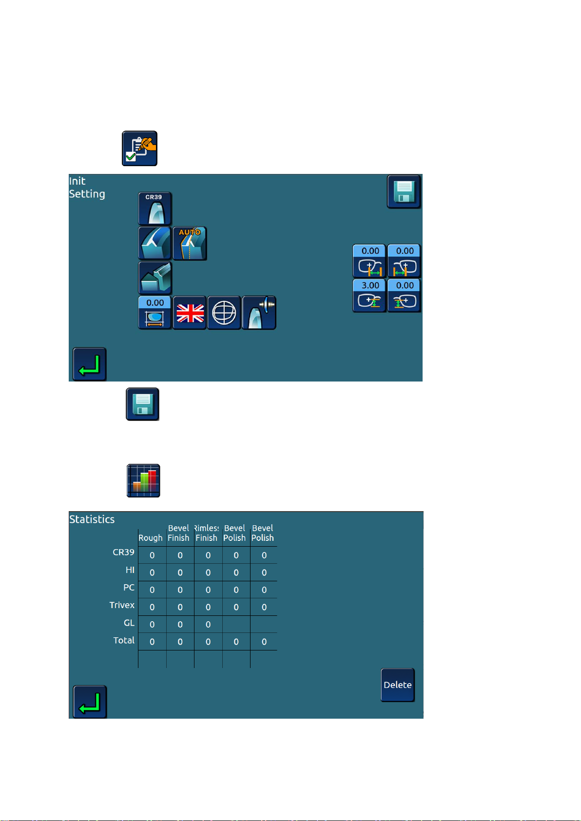
4.1.6 INITIAL PARAMETER SETTING
>Press icon enter initial parameter setting menu.
>Press icon after setting, saving initial parameter setting.
4.1.7 PROCESSING STATISTICS TABLE
>Press icon to view the processing statistics.
- 39 -
Page 41
5. DAILY MAINTENANCE OF MACHINERY
#1 Turn off the power switch if the machine is on;
#2 Gently wipe the touch screen with soft, dry linen.
5.1 MAINTENANCE INSTRUCTIONS
To ensure that your edger is at its best, you must perform several maintenance operations to
achieve the desired results within a range.
> Clean touch screen
> Maintenance of edger
>> Use water spray bottle to clean the edger
>> Regular replacement of movable lens block (every 100 lenses)
>> Regularly check the lens scanning probe, and change the prove once the wear or damage
is found (or replacement per 3000 lenses)
>> Clean the baffle board and replace when necessary.
>> If the machine uses circulating water, replace the water in the tank regularly.
>> Wash the filter and water tank regularly.
>> Check the situation of each piece of grinding wheel. Please replace them under the
technical person instruction when necessary.
5.2 MAINTENANCE OF TOUCH SCREEN PARTS
Warning:
Disable such products as water or chemical reagents.If the stain is difficult to clean For dry
cloth,it can be treated with alcohol. Damage caused by improper maintenance the touch screen,
not within the warranty scope.
- 40 -
Page 42
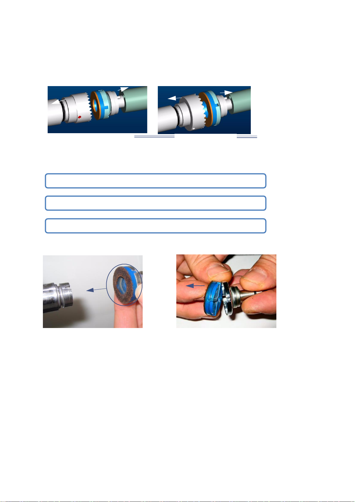
5.3 REPLACE REMOVABLE CLAMPS
19 mm diameter adaptors
25 mm diameter adaptors
19mm small clamp
25mm big clamp
#1 Gently remove the right clamp from the clamp shaft;
#2 Remove the old rubber pad from the clamp-on and replace it with a new one;
#3 Put the right chuck back on the clamp axis.
Note: the lens holder is serrated and the lens probe is sharp. When touching the head and probe,
make sure your hands are protected.
5.3.1 REPLACE THE RIGHT CLAMP RUBBER PAD
Replace the rubber pad procedure as below:
As below pictures:
- 41 -
Page 43
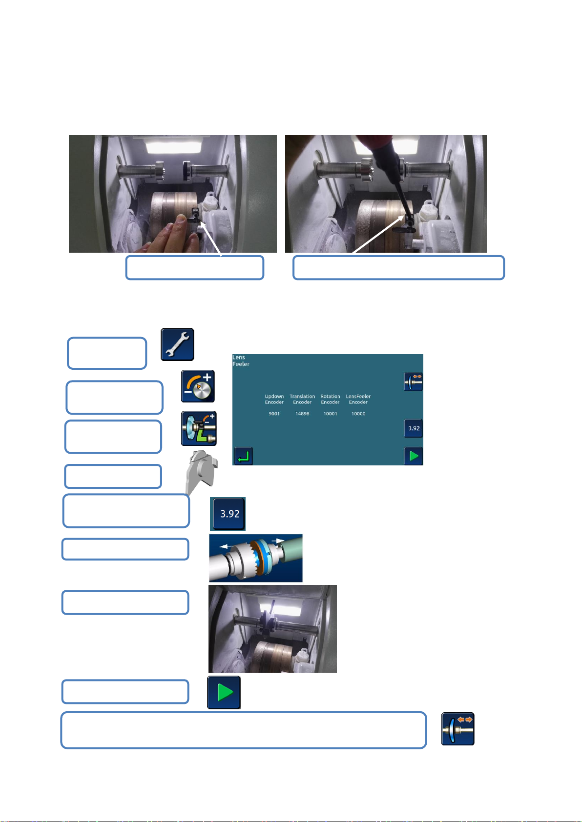
5.4 REPLACE LENS FEELER
#1 Enter the
menu
#2 Enter setup
interface
#3 Enter setup
interface
#4 Take out tool
#5 Input correction tool
thickness value
#6 Replace the 25mm clamp
#7 Load calibration tool
#8 Start calibrating
#9 The machine starts the calibration procedure, saves the calibration parameters automatically,
and then takes out the calibration tool when the calibration is completed.
25mm 大夹头
Dismountable lens feeler
Remove the screws and replace the lens feeler
> Check the lens scanner regularly,change the it once the wear or damage is found(Or replace
every 3,000 lenses).
>After the lens feeler is replaced, the lens feeler position needs to be recalibrated.
The calibration probe procedure is as follows:
>>
>>
>> >>
>>
>>
>>
>>
>>
>>
- 42 -
Page 44
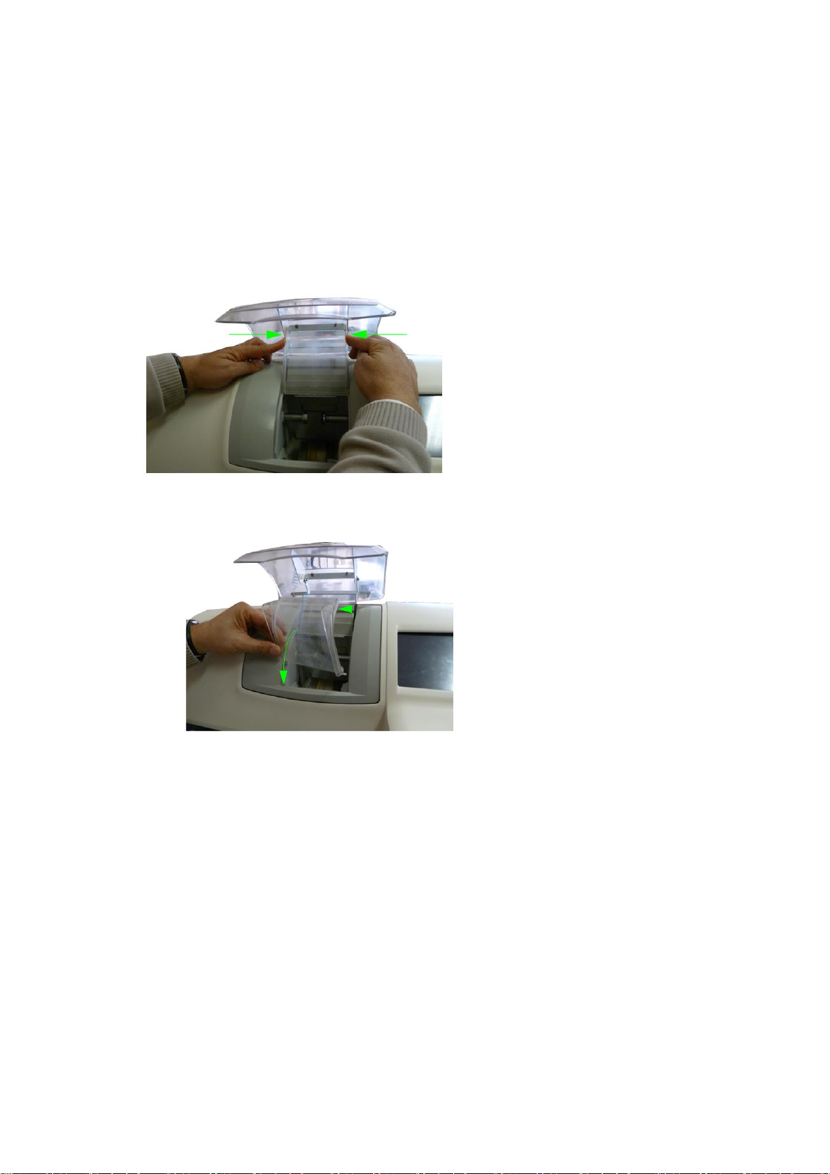
5.5 CLEAN/REPLACE WATER-PROOF COVER
#1
#2
> Before starting any operation, you must ensure that the machine switch is Off: the On/Off
switch is in the Off position and the main power is disconnected.
The replacement procedure is as follows:
NOTE:
> Regular cleaning of the cover plate can clearly see the grinding edge chamber and the
processing process;
> The use of circulating water will affect the cleaning level of the water retaining board.
- 43 -
Page 45
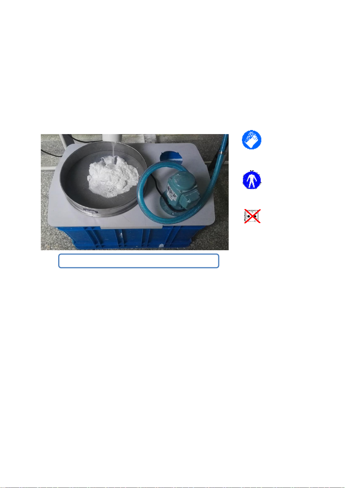
5.6 CLEAN THE FILTER AND WATER TANK
Please clean the water tank and filter regularly!
> Before starting any operation, you must ensure that the machine switch is Off: the On/Off
switch is in the Off position and the main power is disconnected.
> Regular cleaning can ignore the number of lenses to be processed, but the manufacturer's
recommendation is to clean about 100 pieces of lens (glass and plastic) per process.
> Gloves and eye masks must be wear-resistant. It's better to wear overalls.
- 44 -
Page 46

6. TECHNICAL SPECIFICATIONS
6.1 FEATURES
> Automatic initialization
> Three - dimensional probe front & rear surface camber
> wheel configuration:
>> Glass grinding wheel
>> Resin rough wheel
>> Bevel/flat edge grinding wheel
>> Bevel/flat edge polishing wheel
> Automatic clip, three selections of clip pressure, adapt to different material lens processing
> Connect with water pump using circulating water and connect with solenoid valve when
running water
> Grinding diameter
>> <=80 mm
>> Flat(No secured bevel)﹥=19.00mm
>> Bevel(No secured bevel)﹥=19.00mm
> Automatic cleaning of lens fixing system and grinding room
> Lens processing statistics
- 45 -
Page 47

6.2 TECHNICAL PARAMETERS
> The design standard is for indoor use
> Dimension specification
>> Length:705mm
>> Width:465mm
>> Height:442mm
> Weight:75kg
> Input Voltage:220V-230V/50Hz,110V-115V/60Hz
> Machine power:1500W
> Noise:72db
> Operating Temperature:5℃~40℃
> relative humidity:10% - 80%
> Pump working voltage:220V-230V /50Hz,110V-115V /60 Hz
> Pump rated power:<=150W
> FUSE:
220V-230V /50HZ==15A
110V-115V /60Hz==25A
- 46 -
Page 48
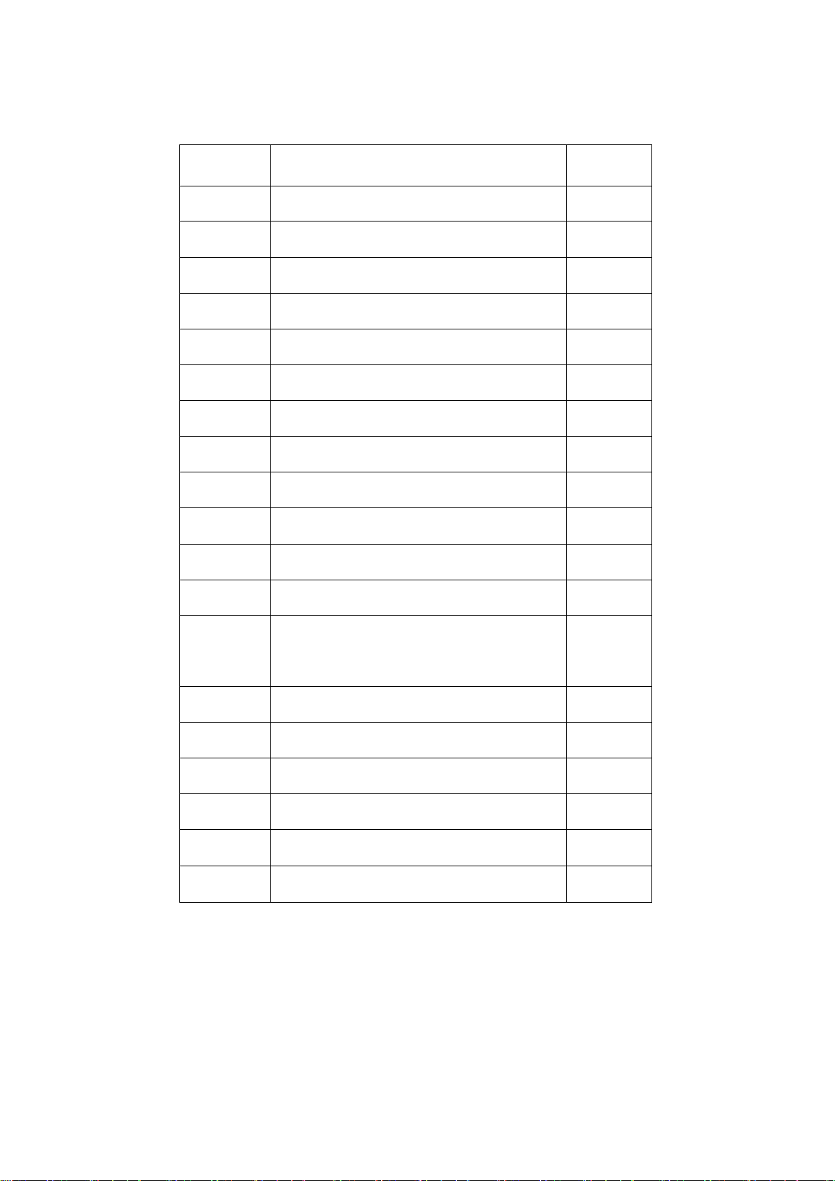
7. ATTACHMENT LIST (PACKING PARTS)
NO.
PART NAME
QUANTITY
1
Block pliers
1 2 Butterfly head correction tool
1 3 Round calibration plate
1
4
Scan probe
3
5
25mm clamp
1
6
19mm clamp
1 7 25mm clamp rubber mat
2
8
19mmclamp rubber mat
2
9
Large block
5
10
Middle block
5
11
Sticker
1
12
Power line
1
13
Fuse
(220V-15A or 110V-25A)
5
14
Certificate of conformity
1
15
Warranty card
1
16
Operation menu
1
17
Drier
2
18
Allen wrench(5*8)
1
19
Drain piper
1
- 47 -
 Loading...