


BST106-N59[B] Shovel Loader Weigher
www.zemicusa.info
Operation Manual V5.0
Changsha Supmeter Technological Co.,Ltd.

Preface
High-Frequency Sampling Multi-filtering Algorithm
Acceleration Compensation High Accuracy&Stablity
www.zemicusa.info
Thank you very much for your purchase!
This manual covers safety precautions, brief introduction, technical specifications, operation interface,
installation&connection, function&operation, fault treatment, working specification and so on. In order to
make the product running at its best, please read this manual in advance, and reserve it for the future
reading.
The continuous technology update, performance perfection and quality improvement may lead to
some differences between this manual and the physical product, please understand.
Without our authorization, the contents of this manual are not allowed to be copied and reproduced.
Main Features:
ARM CPU system with higher arithmetic speed.
Dust-proof stainless Steel shell suitable for dust atmosphere.
EMC design with high anti-jamming capability, suitable for industrial environment.
The DC24V power input circuit of weighing indicator has reverse polarity protection function.
640×480 dots TFT color display screen for English/Chinese character display.
The display information of Bucket Lifting/Declining state, Single-bucket-loading-weight,
Totalized Loading Weight, Positive/Negative Deviation Value, Alarm state, Date/Time and other
auxiliary data are used for adjusting if Single-bucket-loading-weight is valid and the loading
process should be stopped.
Menu&Shortcut mode operation with key tone.
Number, English Alphabet, Simplified/Complex Chinese can be inputted.
The information of User Name, Car.No., Goods No., and Operator No. can be inputted.
Upper/Lower Limit of Single-bucket-loading-weight, Totalized Loading Weight and Date/Time can be set.
Operating Time, Single-bucket-loading-weight, Totalized Loading Weight and Alarm Information can be
recorded automatically.
Using 2 oil pressure sensors for getting higher weighing accuracy than using 1 oil pressure
sensor.
24-bit High-precision and high-speed ∑-△ A/D conversion module with 1,000,000 internal code
used and max. sampling frequency 400Hz.
High sampling frequency, multiple digital filter and acceleration compensation algorithm for
ensuring high weighing accuracy in the lifting process of the bucket.
1000 Loading Records can be saved, queried and printed, and each record can contain 50pcs
Single-bucket-loading-weight value.
1000 Reload Records can be saved and open for reloading.
Auto-locking, Key-locking, Key-unlocking, Digital Setting&Calibration and I/O Testing
functions available.
1

Contents
www.zemicusa.info
1. SAFETY PRECAUTIONS .............................................................................................................. 4
2. BRIEF INTRODUCTION ............................................................................................................... 5
2.1 OPERATING PRINCIPLE .......................................................................................................................... 5
2.2 SYSTEM CONFIGURATION ...................................................................................................................... 5
2.3 APPLICABLE SHOVEL LOADERS............................................................................................................. 5
3. TECHNICAL SPECIFICATIONS ................................................................................................. 6
3.1 TECHNICAL SPECIFICATION OF WEIGHING INDICATOR .......................................................................... 6
3.2 TECHNICAL SPECIFICATION OF OIL PRESSURE SENSOR ......................................................................... 7
3.3 TECHNICAL SPECIFICATION OF POSITION SENSOR ................................................................................. 8
3.4 SYSTEM ACCURACY .............................................................................................................................. 8
4. OPERATION INTERFACE ........................................................................................................... 8
4.1 MAIN DISPLAY INTERFACE .................................................................................................................... 8
4.2 KEYPAD DIAGRAM ................................................................ .............................................................. 11
4.3 KEYPAD OPERATION............................................................................................................................ 11
4.3.1 Menu Operation & Parameter Setting Operation .......................................................................11
4.3.2 Operation for System Calibration .............................................................................................. 12
4.3.3 Operation in Loading Process ................................................................................................... 12
5. INSTALLATION&CONNECTION ............................................................................................. 13
5.1 INSTALLATION ..................................................................................................................................... 13
5.1.1 Structure of Shovel Loader ........................................................................................................ 13
5.1.2 Installation of Weighing Indicator ............................................................................................. 14
5.1.3 Installation of Position Sensor ................................................................................................... 15
5.1.4 Installation of Oil Pressure Sensor ............................................................................................ 16
5.1.5 Cable Laying ............................................................................................................................. 17
5.2 TERMINAL ........................................................................................................................................... 17
2

5.3 CONNECTION....................................................................................................................................... 18
www.zemicusa.info
5.3.1 Oil Pressure Sensor Connector (LC-DN/LC-UP) ...................................................................... 18
5.3.2 Position Sensor Connector (POSITION) ................................................................................... 18
5.3.3 Power Supply Connector (POWER) ......................................................................................... 19
6. SYSTEM ADJUSTMENT&CALIBRATION PROCEDURE ................................................... 20
7. FUNCTION&OPERATION ......................................................................................................... 21
7.1 MAIN MENU ........................................................................................................................................ 21
7.2 PARAMETER SETTING .......................................................................................................................... 23
7.2.1Weighing Parameters .................................................................................................................. 23
7.2.2 Calibration Parameters .............................................................................................................. 24
7.2.3 Setpoint Parameters ................................................................................................................... 24
7.2.4 Alarm Parameters ...................................................................................................................... 25
7.2.5 Communication Parameters ....................................................................................................... 26
7.2.6 Display Parameters ................................ ................................................................ .................... 26
7.3 SYSTEM CALIBRATION ........................................................................................................................ 27
7.3.1 Zero Calibration【Zero】 ......................................................................................................... 27
7.3.2 Zero Compensation【Z.cmp】 ................................................................................................. 28
7.3.3 Span Calibration【Cal】 ........................................................................................................... 29
7.3.4 Span Compensation【S.cmp】 ................................................................................................. 30
7.3.5 Loading Test .............................................................................................................................. 31
8. FAULT TREATMENT .................................................................................................................. 32
9. WORKING SPECIFICATION ..................................................................................................... 33
9.1 BRIEF DESCRIPTION ............................................................................................................................ 33
9.2 DETAILED DESCRIPTION ...................................................................................................................... 34
APPENDIX A. PRINT FORMATS .................................................................................................. 36
APPENDIX B. REGISTER TABLE OF HOST-SLAVE MODBUS[ASCII] ................................ 37
3

1. Safety Precautions
www.zemicusa.info
Lithium Battery Installation
A Lithium battery should be equipped in the weighing indicator. If it is not allowed to be
transported together with the product because of embargo, please make a purchase
according to the model offered by us and install it by yourself.
Prohibit using the product under dangerous environment
Prohibit using the product under the dangerous environment with combustible gas and
explosive dust. If you have this need, please use our explosion-proof products.
Avoid using the product under overheated environment
Make sure that the weighing indicator works under the environment with allowed temperature
range to get good performance and long working life.
Please keep the product away from direct sunlight.
Installation & Power Supply of Weighing Indicator
Weld the mounting bracket of the weighing indicator firmly on the metal frame of the shovel
loader driving cab. The installation position should be convenient for operation.
The power switch of the weighing indicator should be turned off and ensure that the power
cables are not charged before DC24V power connection to avoid short circuit fault.
Please make sure that the power supply is correct before power-on.
Installation of Oil Pressure Sensor
Strictly follow the ‘Safety Precaution’ described in ‘5.1.4 Installation of Oil Pressure Sensor’.
Install the oil pressure sensors and plate type three-way joints firmly, and seal them as
prescribed to avoid oil leaking.
Installation of Position Sensor
Install the position sensor according to required position and angle, and adjust Detecting
Distance to 3~5mm.
Cable Laying
Oil pressure sensor signal calble and position sensor signal cable should be laid in flexible
pipe for protection, and fix them with nylon strip.
Try to keep signal calbles away from the place with high temperature and possible extrusion,
and reserve enough bending length to avoid being pulled apart.
Environmental Protection
Before the Lithium battery equipped in the weighing indicator being discarded, please
insulate its positive or negative pole, do not put it into fire.
Although the weighing indicator is made of the lead-free components, after used in the
industrial environments, it’s possible to be polluted. So, while being discarded as worthless,
the weighing indicator should be processed lawfully as leady industrial waste for environment
protection.
Other Notes
The installation, wiring and maintenance should be operated by the engineers with the
relevant professional knowledge and safety operation ability. Although being not described in
this manual, the relevant safety operating procedures and standards should be followed.
4

2. Brief Introduction
www.zemicusa.info
2.1 Operating Principle
Shovel Loader Weigher is a dynamic weighing and auto-totalizing equipment installed on shovel
loader without changing the original structure of shovel loader.
When the lift-arm of Shovel Loader is lift to a certain height, the position sensor will trigger the
weighing process, and the weighing indicator will collect the oil pressure signals from lower and
upper oil chambers of arm-lifting oil cylinder. After signal processing and compensation,
Single-bucket-loading-weight will be got and totalized to Totalized Loading Weight automatically,
and the Deviation Value between Totalized Loading Weight and Setpoint, alarm messages will be
displayed. The operator can judge if the present Single-bucket-loading-weight is valid according to
the alarm messages, and confirm the loading weight of last bucket according to Negative Deviation
Value for avoiding overloading. After Totalized Loading Weight reached setpoint, the operator should
stop loading process, save and print Loading Record.
2.2 System Configuration
1 Weighing Indicator with Thermal Printer.
2 Oil Pressure Sensors [0~25MPa].
2 Plate Type Three-way Joints.
1 Position Sensor [Detecting Distance: 5~8mm].
1 Mounting Fitting.
2.3 Applicable Shovel Loaders
Suitable for shovel loader with loading capacity 1~12t:
LiuGong ZL Series.
XiaGong XG Series.
LongKing ZL/LG Series.
XuGong ZL/LW Series.
JinGong ZL/ JGM Series.
LinGong LG Series.
ChengGong ZL/CG Series.
CAT Series……
5

3. Technical Specifications
www.zemicusa.info
3.1 Technical Specification of Weighing Indicator
Product Executing Standard
CMC GB/T7724-2008《Electronic Weighing Meter》PRC National Standard.
OMIL R76: 2006《Non-automatic Weighing Instruments》International Recommendation.
Weighing Accuracy
Accuracy Grade: III .
Number of Nerification Intervals: n=3000.
Error Distribution Coefficient: P=0.5.
Power Supply
Operating Voltage: DC24V±20%.
Max. Power: 10W.
Display
640×480 dots TFT color display screen for English, Simplified/Complex Chinese character
display.
Kaypad
20 keys for Menu&Shortcut mode operation with key tone.
Optional English keypad, Simplified Chinese keypad and Complex Chinese keypad.
Number, English Alphabet, Simplified/Complex Chinese can be inputted.
Auto-locking, Key-locking, Key-unlocking, Digital Setting&Calibration and I/O Testing functions
available.
Weighing Range: 100~12,000kg.
Display Division: 1kg, 5kg, 10kg, 50kg.
Oil Pressure Sensor Input Interface (LD-UP/LD-DN)
2 Oil Pressure signal inputs.
Signal Input Range: 4~20mA.
Excitation Voltage Output: DC12V.
Weighing Signal Sampling Circuit
24-bit ∑-△ADC with 1,000,000 internal code used.
Max. Sampling Frequency: 400Hz.
Zero Drift: ±0.1μV/℃ RTI (Relative to Input).
Gain Drift: ±5ppm/℃.
Non-linearity: 0.005%FS.
6

Position Sensor Input Interface (POSITION)
www.zemicusa.info
1 Switch signal Input.
Excitation Voltage Output: DC12V.
Print Port (PRINTER)
RS232.
Digital Communication Interface (COM1)
RS232。
Connectable: IPC/PLC and Wireless Module.
Report Print
1000 Loading Records can be saved, queried and printed, and each record can contain 50pcs
Single-bucket-loading-weight value.
Outline Dimension
168 × 213 × 50 mm (W×H×D).
Cut Dimension
Model Horizontal Panel-mounting: 153 × 77 mm (W×H).
Model Vertical Panel-mounting: 77 × 153 mm (W×H).
Weight Approx. 2.0kg.
Temperature and Humidity
Service Temperature: -20℃ to +40℃.
Storage Temperature: -30℃ to +60℃.
Relative Humidity: Max. 85%RH.
Protection Level: IP65.
3.2 Technical Specification of Oil Pressure Sensor
Supply Voltage: DC9~36V.
Capacity: 0~25MPa or 0~40Mpa.
Output Signal: 4~20mA.
Long term stability 1year @ +25℃: ±0.3%FS.
Overpressure: 100MPa.
Burstpressure: 200MPa.
Connector: M12×1mm.
Operating Temperature: -40℃~+125℃.
Protection Level: IP67 with connector installed.
Approvals: CE/EMC.
7

3.3 Technical Specification of Position Sensor
GOODS: 00
OP.: 01
SET: 60.00t
[6]
[7]
[2]
CARNO: 00000
Left[9]/Right[10]
[11]
[5]
4.500 t
[1]
[3]
[4]
[12]
LOAD [LOCK] 05-20-2009 23:59:45
OK
12
+1.200t
61.200t
USER:
ADD
[8]
[13]
www.zemicusa.info
HALL Type Proximity Switches
Operating Voltage: DC5~24V.
Detecting Distance: 5~8mm.
Response Frequency: 5KHz.
Quiescent Current:Max. 2mA.
Thread Size: M8×1mm.
Service Temperature: -25℃~+70℃.
Protection Level: IP67.
Standard Detecting Target: Magnet.
3.4 System Accuracy
Accuracy of Single-Bucket -Weight: 0.5%~1.0%FS.
Accuracy of Totalized Loading Weight: ±1.0% (OIML Y(b) Accuracy Grade).
4. Operation Interface
4.1 Main Display Interface
8

No.
Sign
Description
[1]
Working State
LOAD: Loading state.
DEDUCT: Deducting state with flashing yellow background.
PAUSE: Pause state with flashing red background.
[LOCK]: Keypad is locked.
[903] Date Format Hour : Minute : Second
[2]
CARNO
Car No.
[3]
GOODS
Goods Name.
[4]
OP.
Operator Name.
[5]
SET
Setpoint Value.
[6]
Blue ▲
The bucket of shovel loader is below the position sensor.
Blue ▼
The bucket of shovel loader is above the position sensor.
Red ■
Pause State.
[7]
OK
Weighing Normal.
STALL
The operator has released the accelerator of shovel loader in weighing process:
Acceleration Value < [400] Stall Alarm Point.
LOW
Lower Limit Alarm of Single-bucket-loading-weight:
Loading Weight < [401] Load Lower Limit.
HIGH
Upper Limit Alarm of Single-bucket-loading-weight:
Loading Weight > [402] Load Upper Limit.
UND-T
Undertime Alarm: Weighing Time < [403] Min. Weighing Time.
OV-T
Overtime Alarm: Weighing Time > [404] Max. Weighing Time.
[8]
USUER
User Name.
[9]
Bucket Count
The display area of „Bucket Count‟ will change to red background if the key【Void】
is pressed for „Cancel Totalizing‟ or „Cancel Deducting‟.
[10]
Deviation Value
Deviation Value = Totalized Loading Weight-Setpoint Value.
[11]
Totalized
Loading Weight
“Last Bucket” Prompt: The display area of „Totalized Loading Weight‟ will change
to red background if „Negative Deviation Value<3t‟, it means that the next bucket
may be the last one, the operator should determine the loading weight of the next
bucket according to the actual Negative Deviation Value.
[12]
Single-bucketloading-weight
The display area of „Single-bucket-loading-weight‟ will change to flashing red
background while alarming.
[13]
TOT
The present Single-bucket-loading-weight has been totalized to Totalized Loading
Weight.
NO TOT
The present Single-bucket-loading-weight has not been totalized to Totalized
Loading Weight because of alarming.
After totalizing, the present Single-bucket-loading-weight can be deducted from
Totalized Loading Weight via the key【Void】.
Refer to parameter [406] „Totalizing/Deducting Permission While Alarming‟.
DED
The present Single-bucket-loading-weight has been deducted from Totalized Loading
Weight.
NO DED
The present Single-bucket-loading-weight has not been deducted from Totalized
Loading Weight because of alarming.
After deducting, the present Single-bucket-loading-weight can be totalized to
Totalized Loading Weight again via the key【Void】.
Refer to parameter [406] „Totalizing/Deducting Permission While Alarming‟.
www.zemicusa.info
9

Press key【Display】to switch the following display interfaces:
AD1: XXXXX
AD2: XXXXX
AD: XXXXX
NET: 0.000t
T2: 0.000s
T3: 0.000s
ACC: 0.0000
T1: 0.000s
V3: 0.000
A0: 0.0000
LR: 1.000
V1: 0.000
Z.CMP: 0
SPAN: 1000
S.CMP: 0
ZERO: 10000
R-AD1: XXXXX
R-AD2: XXXXX
R-AD: XXXXX
R-NET: 0.000t
1. Display Interface A for Testing Oil Pressure Sensor
R-NET: Real-time Weight Value.
R-AD1: Oil Pressure Signal Real-time AD Value from Lower Oil Chamber.
R-AD2: Oil Pressure Signal Real-time AD Value from Upper Oil Chamber.
R-AD: Real-time AD Value = [R-AD1]-[R-AD2].
2. Display Interface B for Testing Oil Pressure Sensor
NET: Single-Bucket-Loading-Weight without Acceleration Compensation.
AD1: Oil Pressure Signal Average AD Value from Lower Oil Chamber in Weighing
Process.
AD2: Oil Pressure Signal Average AD Value from Upper Oil Chamber in Weighing
Process.
AD: AD Value at Weighing Segment = AD1-AD2.
3. Display Interface A for Testing Position Sensor
T1: Time spent by Upper Magnet Block passing by Proximity Switch [s].
T2: Time spent by Proximity Switch running between two Magnet Blocks [s].
T3: Time spent by Lower Magnet Block passing by Proximity Switch [s].
ACC: Acceleration Value at Weighing Segment [dm/s2].
4. Display Interface B for Testing Position Sensor
V1: Average Speed of Upper Magnet Block passing by Proximity Switch [m/s].
V3: Average Speed of Lower Magnet Block passing by Proximity Switch [m/s].
A0: [208] IdleAcc.Value (Acceleration Value at Idle Speed) [dm/s2].
LR: [205] Run Length Ratio.
5. Calibration Parameters display Interface
ZERO: [200] Zero Value.
Z.CMP: [201] Zero Compensation Coefficient.
SPAN: [202] Span Coefficient.
S.CMP: [203] Span Compensation Coefficient.
www.zemicusa.info
10

4.2 Keypad Diagram
Key Name
Description
【Menu】
Enter Main Menu / Exit.
【Ent】
Enter/Save.
【◄】
Cursor shifts left.
Backspace.
【►】
Cursor shifts right.
【▲】
Cursor shifts up.
Display the previous option.
【▼】
Cursor shifts down.
Display the next option.
【Set】
Setpoint Parameters Setting.
【No.】
Input Car Number.
【0~9】
Number Input.
【A-Z】
English Alphabet Input.
【Print】
Input Method [Number/English/Chinese] Switch.
www.zemicusa.info
4.3 Keypad Operation
If there is not any keypad operation in one minute and it‟s not in the processes of „F2 Calibration‟ & „F7 Factory
Adj.‟, the weighing indicator will return to „Main Display Interface‟ automatically.
4.3.1 Menu Operation & Parameter Setting Operation
11

4.3.2 Operation for System Calibration
No.
Key Name
Description
1
【Disp】
Display Interface Switch.
2
【Lock】
Key-locking .
Key-unlocking.
3
【Deduct】
Deduct the next Single-bucket-loading-weight from Totalized
Loading Weight.
4
【Zero】
Zero Calibration with unloading and idle speed.
5
【Cal】
Span Calibration with loading and idle speed.
6
【Mode】
Unused.
7
【Z.cmp】
Zero Compensation with unloading and accelerating.
8
【S.cmp】
Span Compensation with loading and accelerating.
9
【Rec】
Query/Print Loading Records.
Reload: Find and open record from the buffering database of
„Reloading Records‟ for reloading.
0
【Cls】
Clear Screen without Saving Present Loading Record.
Key Name
Description
【Load】
Enter Loading state (Display blue sign „▲‟).
It‟s necessary to let the bucket of shovel loader stay at the lowest position
before pressing【Load】.
【Finish】
[Save]: Save&Print Loading Record and Clear Screen after Loading
process finished.
[Buffer]: Save Loading Record into the buffering database of
„Reloading Records‟ and Clear Screen.
[Cls]: Clear Screen without saving Loading Record.
[Exit].
【Pause】
Enter Pause state (Display red sign „■‟).
【Void】
Cancel Totalizing: After totalizing, the present
Single-bucket-loading-weight can be deducted from Totalized
Loading Weight via this key.
Cancel Deducting: After deducting, the present
Single-bucket-loading-weight can be totalized to Totalized Loading
Weight again via this key.
【Print】
Print Loading Records.
【On/Off】
Press it to turn the power on.
Keep it pressed for 2 seconds to turn the power off.
www.zemicusa.info
4.3.3 Operation in Loading Process
12

5. Installation&Connection
2
3
4 1 5
www.zemicusa.info
5.1 Installation
5.1.1 Structure of Shovel Loader
1: Bucket; 2: Lift-arm; 3: Arm-lifting Oil Cylinder; 4: Oil Connecting Port of Upper Oil Chamber;
5: Oil Connecting Port of Lower Oil Chamber.
Related Operation Terms:
Arm-up: Lift the lift-arm so that the bucket rises.
Arm-down: Put the lift-arm down so that the bucket goes down to the lowest position.
Bucket-up: Flip the bucket upward to the limit position.
Bucket-down: Flip the bucket downward.
Discharge: Flip the bucket downward for discharging materials.
Shovel: Shovel materials into the bucket.
13

5.1.2 Installation of Weighing Indicator
Weld the mounting bracket of the weighing indicator firmly
on the metal frame of the shovel loader driving cab. The
installation position should be convenient for operation.
Suggestion: Install the weighing indicator in the driving cab of
shovel loader and on the side the door will not be opened
frequently.
1 2 3
4
www.zemicusa.info
1: Fastening Nut for Lateral Rotation; 3: Fastening Nut for Vertical Rotation; 4: Printer
14

5.1.3 Installation of Position Sensor
7
2
1
9
10
11
12 5 3
4 6 8
www.zemicusa.info
Position sensor includes two modules:
Proximity Switch module: Main Mounting Plate with a chute for length adjustment,
Sub-mounting Plate with a chute for angle adjustment and Proximity Switch [Detecting Distance:
5~8mm].
Magnet Module: Thread Pole, Weld-nut, Tight-nut, Nylon Block, Upper Magnet Block and Lower
Magnet Block.
1: Lift-arm Seat; 2: Lift-arm; 3: Main Mounting Plate;4: Sub-mounting Plate; 5: Weld-nut;
6: Thread Pole; 7: Upper Magnet Block; 8: Nylon Block; 9: Lower Magnet Block; 10: Proximity Switch;
11: Fastening Nut for Length Ajustment; 12: Fastening Nut for Angle Ajustment.
Detecting Distance Adjustment:
Method 1: Adjust the distance between the
inductive surface of proximity switch and
magnet block to 5mm.
Method 2: Adjust the distance between the
inductive surface of proximity switch and
Nylon Block to 8mm.
Suggestion: Install the position sensor on the
lift-arm seat and lift-arm which are at the same side
that the weighing indicator installed on.
15

5.1.4 Installation of Oil Pressure Sensor
1. Intallation Position
The upper oil connecting port and lower oil connecting port of
arm-lifting oil cylinder are the installation positions of oil
pressure sensors.
Suggestion: Install the oil pressure sensors on the arm-lifting
oil cylinder which is at the same side that the weighing
indicator installed on.
2. Safety Precaution
Using a stable and strong base to support the bucket of the
loader for avoiding accidental injury.
In the process of dismounting and mounting, the shovel loader
should be kept at flameout state.
Put a bucket under the oil connecting ports that will be
dismounted for oil collecting.
If the shovel loader has worked for a long time, the oil
temperature in the bucket-lifting cylinder will be very high.
Please let the shovel loader at flameout state for some time
before dismouting to avoide scalding.
Before dismounting the oil connecting port of the upper oil
chamber, let the bucket-lifting action bar stay at the position of
„LIFT‟ for making the upper oil chamber connect with main oil
tank and relief pressure.
Before dismounting the oil connecting port of the lower oil
chamber, let the bucket-lifting action bar stay at the position of
„FALL‟ for making the lower oil chamber connect with main
oil tank and relief pressure.
When somebody stays in driving cab, do not stay under the
shovel loader for avoiding accidental injury.
3. Installation
Wrap some sealing ribbons on the screw of oil pressure sensor
avoid oil leakage, and install it on the three-way joint firmly.
Fix the three-way joint [thickness: 19mm/21mm] and the oil
tube connector on the arm-lifting oil cylinder by the
lengthened screw rods which is about 20mm longer than
original screw rods.
4. Check Oil Passage
Start shovel loader, and lift the lift-arm and bucket with
accelerating for several times.
Check if there is the phenomenon of oil leakage at the oil
connecting ports.
www.zemicusa.info
16

5.1.5 Cable Laying
4
5
1
3 2 3 4 1 2 2
1
POWER
POSITION
LC-DN
LC-UP
9
34681
COM1
ON
OFF
4
5
1
3
2
www.zemicusa.info
Oil pressure sensor signal calble and position sensor signal cable should be laid in flexible pipe for
protection, and fix them with nylon strip.
Try to keep signal calbles away from the place with high temperature and possible extrusion, and
reserve their bending length enough to avoid being pulled apart.
5.2 Terminal
17

5.3 Connection
No.
Pin
Description
1
SIG-
4~20mA Weighing Signal Input -.
2
SIG+
4~20mA Weighing Signal Input +.
3
EXC-
Excitation Voltage Output - for Oil Pressure Sensor .
4
EXC+
Excitation Voltage Output + for Oil Pressure Sensor (DC12V).
5
SHD
Shield.
No.
Pin
Description
1
VS+
Excitation Voltage Output + for Oil Pressure Sensor ( DC12V).
2
SIN-A
Position Sensor A Signal Input.
3
SIN-B
Position Sensor B Signal Input.
Unused.
4
VS-
Excitation Voltage Output - for Oil Pressure Sensor.
5
SHD
Shield.
POSITION
3 4 1 2 4 5 1 3 2
LC-DN/LC-UP
www.zemicusa.info
5.3.1 Oil Pressure Sensor Connector (LC-DN/LC-UP)
Oil Pressure Sensor is definable via parameter [106] „Loadcell Channel‟ with default value „2: LC-DN-UP‟:
LC-DN: Connect the oil pressure sensor on the lower oil chamber of arm-lifting oil cylinder.
LC-UP: Connect the oil pressure sensor on the upper oil chamber of arm-lifting oil cylinder.
5.3.2 Position Sensor Connector (POSITION)
18

5.3.3 Power Supply Connector (POWER)
No.
Pin
Wire Color
Description
Voltage
1
GND
Black
DC Input -
DC24V±20%
2
+24V
Red
DC Input +
Note: Reverse polarity protection function available.
2
1
POWER
www.zemicusa.info
The power switch of the weighing indicator should be turned off and ensure that the power cables are not
charged before DC24V power connection to avoid short circuit fault.
Find the DC24V terminal with relative stable voltage in the driving cab, then connect the terminal „+24V‟of
the weighing indicator to the FUSE, and connect „GND‟ to the metal frame of the driving cab.
Please make sure that the power supply is correct before power-on.
19

6. System Adjustment&Calibration Procedure
Power on
Zero Calibration
Loading Opertaion
Loading Test
Zero Compensation
Span Calibration
Span Compensation
Oil Pressure Sensor Testing
and Parameters Setting
Position Sensor Testing
and Parameters Setting
www.zemicusa.info
20

7. Function&Operation
Main Menu
Second Menu
Description
1: SET
[Para. Setting]
1 Weighing
Weighing parameters setting.
2 Calibration
Calibration parameters setting.
3 Setpoint
Setpoint parameters setting.
4 Alarm
Alarm parameters setting.
5 Communcation
Communication parameters setting.
6 Display
Display and operation interface parameters setting.
2: CAL
[System
Calibration]
1 Zero Cal. [Unload&Idle]
Zero Calibration.
Lift the lift-arm and bucket of shovel loader with unloading
and idle speed for correcting Zero Value, Run Length Ratio
or IdleAcc.Value (Acceleration Value at Idle Speed).
2 Zero Comp. [Unload&ACC]
Zero Compensation.
Lift the lift-arm and bucket shovel loader with unloading and
accelerating for correcting Zero Compensation Coefficient.
3 Span Cal. [Load&Idle]
Span Calibration.
Lift the lift-arm and bucket shovel loader with loading and
idle speed for correcting Span Coefficient.
4 Span Comp. [Load&ACC]
Span Compensation.
Lift the lift-arm and bucket shovel loader with loading and
accelerating for correcting Span Compensation Coefficient.
3: REC
[Record Query]
1 Loading Records
Query Loading Records.
2 Reloading Records
Query Reloading Records.
Find and open record from the buffering database of
„Reloading Records‟ for reloading.
3 Operation Records
Query Operation Records.
4: CLR
[Data Clearing]
1 Clear Screen
Clear Screen with Saving Loading Record.
2 Clear Loading Rec.
Clear Loading Records.
3 Clear Reloading Rec.
Clear Reloading Records.
4 Clear Operation Rec.
Clear Operation Records.
www.zemicusa.info
7.1 Main Menu
21

Main Menu
Second Menu
Description
5: LOC
[Key-locker]
1 Key-unlocking
Unlocking keypad.
2 Key-locking
Locking keypad.
3 Password Set
Exfactory Passwords:
Operator Password: 000000.
Administrator Password: 000001.
6: TIME
[Time Setting]
1 Date
[903] Date Format.
2 Time
Hour: Minute: Second.
3 Week
Monday ~ Sunday.
7: FAC
[Factory Adj.]
1 Hardware Test
AD Value of Weighing Signal Linearity Test and Position
Signal Test.
2 Simplified Chinese
Download Simplified Chinese.
3 Complex Chinese
Download Complex Chinese.
4 Para. Backup
Parameter Backup.
5 Para. Recovery
Parameter Recovery.
6 Reset Defaults
Reset to factory defaults.
8: INF
[Product Info.]
1 Version No.
Only for query.
2 Serial No.
Only for query.
3 Exfactory Date
Only for query.
4 Auth. Code
Authorization Code.
Only for query.
www.zemicusa.info
22

7.2 Parameter Setting
No.
Range
Default
Description
Set
100
0~1
1
Load Weight Unit
Display Unit of Loading Weight.
0: kg
1: t
Note: Internal Scale Unit is kg.
101
0~1
1
TOT Weight Unit
Display Unit of Totalized Loading Weight.
0: kg
1: t
102
0~3
3
Ton-Decimal
0: o; 1: o.o; 2: o.oo; 3: o.ooo
103
1~50
10
Display Division
1, 2, 5, 10, 20, 50
If the Weight Variance without Decimal Point is less
than Display Division value, the display value will not
change. 104
0~200
50
Zero Range [kg]
105
0~5
5
ADC Frequency [Hz]
ADC Sampling Frequency.
0: 5; 1: 10; 2: 50; 3: 100; 4: 200; 5: 400
106
0~3
2
[*]
Loadcell Channel
0: LC-DN [Connect „LC-DN‟ to the oil pressure
sensor on the lower oil chamber of arm-lifting oil
cylinder; „LC-UP‟ is unused]
1: LC-UP [Connect „LC-UP‟ to the oil pressure
sensor on the lower oil chamber of arm-lifting oil
cylinder; „LC-DN‟ is unused]
2: LC-DN-UP [Connect „LC-DN‟ to the oil pressure
sensor on the lower oil chamber of arm-lifting oil
cylinder and connect „LC-UP‟ to the oil pressure
sensor on the upper oil chamber ]
3: LC-UP-DN [Connect „LC-UP‟ to the oil pressure
sensor on the lower oil chamber of arm-lifting oil
cylinder and connect „LC-DN‟ to the oil pressure
sensor on the upper oil chamber ]
www.zemicusa.info
7.2.1Weighing Parameters
* „Reset Defaults‟ operation has no effect on this parameter.
23

7.2.2 Calibration Parameters
No.
Range
Default
Description
Set
200
0~130000
10000
Zero Value [AD Value]
Zero Value at Idle Speed.
201
0~999999
10000
Zero Comp.Coeff.
Zero Compensation Coefficient at Accelerated Speed.
202
1~999999
1000
Span Coefficient
Span Coefficient at Idle Speed.
203
0~999999
0
Span Comp.Coeff.
Span Compensation Coefficient at Accelerated Speed.
204
5.0~100.0
10.0
Mag.Block Length [mm]
Length of Upper/Lower Magnet Block on Position
Sensor.
205
0.001~9.999
1.000
Run Length Ratio [LR]
Running Length Ratio LR=L1/L3.
L1: The actual running length of Upper Magnet Block
passing by Proximity Switch.
L3: The actual running length of Lower Magnet Block
passing by Proximity Switch.
206
0~250
100
Min. Switch Time [ms]
Min. Valid Time spent by Upper Magnet Block passing
by Proximity Switch.
Min. Valid Time spent by Lower Magnet Block passing
by Proximity Switch.
207
0~1000
500
Max. Comp.Weight [kg]
Max. Compensation Weight.
208
-0.0500
~+0.0500
0.0000
IdleAcc.Value A0 [dm/s2]
Acceleration Value at Idle Speed.
Key【Print】: „+‟/„-‟ switch.
No.
Range
Default
Description
Set
300
8 Characters
0
Car No.
301
8 Characters
01
Goods 302
8 Characters
01
Operator
303
20 Characters
01
User Name
304
0~99999
60000
Setpoint [kg]
www.zemicusa.info
* „Reset Defaults‟ operation has no effect on Calibration Parameters.
7.2.3 Setpoint Parameters
24

7.2.4 Alarm Parameters
No.
Range
Default
Description
Set
400
-0.0500
~+0.0500
-0.0050
Stall AlarmPoint [dm/s2]
If „Acceleration Value < Stall Alarm Point‟, the
weighing indicator will display the alarm message
„STALL‟.
Key【Print】: „+‟/„-‟ switch.
401
0~99999
5000
Load Lower Limit [kg]
Lower Limit of Single-bucket-loading-weight.
If „Loading Weight < Load Lower Limit‟, the weighing
indicator will display the alarm message „LOW‟.
402
0~99999
10000
Load Upper Limit [kg]
Upper Limit of Single-bucket-loading-weight.
If „Loading Weight > Load Upper Limit‟, the weighing
indicator will display the alarm message „HIGH‟.
403
0.000~99.999
0.100
Min. Weigh Time [s]
Min. Weighing Time.
If „Weighing Time < Min. Weighing Time‟, the
weighing indicator will display undertime alarm
message „UND-T‟.
404
0.000~99.999
10.000
Max. Weigh Time [s]
Max. Weighing Time.
If „Weighing Time > Max. Weighing Time‟, the
weighing indicator will display overtime alarm message
„OV-T‟.
405
0~1
1
Alarm Sound
0: OFF
1: ON
406
0~1
0
TOT/DEDwithAlarm
Totalizing/Deducting Permission While Alarming.
0: OFF
1: ON
www.zemicusa.info
25

7.2.5 Communication Parameters
No.
Range
Default
Description
Set
800
0~99
01
Comm. Address
Communication Address.
801
802
0~5
5
3
COM1/COM2 Baud Rate
0: 1200bps; 1: 2400bps; 2: 4800bps
3: 9600bps; 4: 19200bps; 5 :115200bps
803
804
0~2
0
0
COM1/COM2 ParityCheck
0: None; 1: Even; 2: Odd
805
806
0~4
0
2
COM1/COM2 Comm. Mode
Communication Mode.
0: Host-slave ASC [Modbus ASCII]
1: Continuous ASC [Continuous Sending ASCII]
2: Print [A]
3: Print [B]
4: Print [C]
No.
Range
Default
Description
Set
900
0~2
0
Language
0: S-Chinese [Simplified Chinese]
1: C-Chinese [Complex Chinese]
2. English
901
0.1~2.0
0.5
Disp.RefreshTime [s]
Display Refreshing Time.
902
0~1
0
Auto-Locking
0: OFF
1: ON [ If there is not any keypad operation in one
minute and it‟s not in the processes of „F2 Calibration‟
& „F7 Factory Adj.‟, the weighing indicator will lock
the keypad and return to „Main Display Interface‟
automatically ]
903
0~2
0
Date Format
0: YYYY. MM. DD [Year. Month. Day]
1: MM. DD. YYYY [Month. Day. Year]
2: DD. MM. YYYY [Day. Month. Year]
www.zemicusa.info
7.2.6 Display Parameters
26

7.3 System Calibration
New LR: 1.000
Old A0: 0.0000
New A0: 0.0000
Old LR: 1.000
0.000 t
1 Zero Calibration [Unload&Idle-speed]
▲
OK
OldZero
15000
NewZero
0
【Start】
www.zemicusa.info
7.3.1 Zero Calibration【Zero】
Make sure the bucket of shovel loader is empty.
BUCKET-UP: Flip the bucket upward to the limit position.
ARM-DOWN: Put the lift-arm down so that the bucket goes down to the lowest position.
Press key【Load】to display the blue sign „▲‟.
Press key【Zero】to display interface „Zero Calibration‟:
Lift the lift-arm and bucket with idle speed.
After the proximity switch passed by the weighing segment, display:
Blue sign „▼‟.
New Zero Value.
New Run Length Ratio.
New IdleAcc.Value A0 [Acceleration Value at Idle Speed, dm/s2].
Message „Save‟.
Message „Error‟: The detection result exceeds allowed range, and it‟s not allowed to be
saved.
Press key【Load】to display dialogue box „Save A0 or LR?‟.
Press key【◄】/【►】to select the button „Save A0‟, then prsee key【Enter】for saving new
Zero Value and IdleAcc.Value A0, and keep Run Length Ratio unchanged.
Select the button „Save LR‟, then prsee key【Enter】for saving new Zero Value and Run
Length Ratio and reset IdleAcc.Value to zero.
Suggestion: Please select „Save LR‟ at the first time of „Zero Calibration‟, after this, please
select „Save A0‟.
【Menu】: Exit without saving.
Repeat the above steps, if the variation of detection results are in the allowable range, Zero
Calibration process will be completed.
27

7.3.2 Zero Compensation【Z.cmp】
AD: XXXXX
ACC: 0.0000
R-AD: XXXXX
C.ER: 0
0.000 t
2 Zero Compensation [Unload&ACC-speed]
▲
OK
OldComp
0
NewComp
0
【Start】
www.zemicusa.info
Make sure the bucket of shovel loader is empty.
BUCKET-UP: Flip the bucket upward to the limit position.
ARM-DOWN: Put the lift-arm down so that the bucket goes down to the lowest position.
Press key【Load】to display the blue sign „▲‟.
Press key【Z.cmp】to display interface „Zero Compensation‟:
Lift the lift-arm and bucket with the usual accelerator in actual operation and keep the
accelerator stable.
After the proximity switch passed by the weighing segment, display:
Blue sign „▼‟.
New Zero Compensation Coefficient.
Compensation Difference [C.ER = New Zero Compensation Coefficient – Old Zero
Compensation Coefficient].
AD: AD Value at Weighing Segment.
ACC: Acceleration Value at Weighing Segment [dm/s2].
R-AD: Real-time AD Value.
Message „Save‟.
Message „Error‟: The detection result exceeds allowed range, and it‟s not allowed to be
saved.
【Enter】: Save; 【Menu】: Exit without saving.
Repeat the above steps, if the variation of detection results are in the allowable range, Zero
Compensation process will be completed.
28

7.3.3 Span Calibration【Cal】
AD: XXXXX
ACC: 0.0000
R-AD: XXXXX
SP.R: 1.00000
0.000 t
3 Span Calibration [Load&Idle-speed]
▲
OK
OldSpan
1000
NewSpan
0
【Start】
www.zemicusa.info
Use truck scale to get the seft-weight [Tare Weight] of the shovel loader.
Load materials into the bucket with 2/3 bucket, and use truck scale to get the gross weight of the
shovel loader and materials in the bucket.
Calculate Calibrating Weight [Calibrating Weight = Net Weight of Materials = Gross Weight –
Tare Weight]
BUCKET-UP: Flip the bucket upward to the limit position.
ARM-DOWN: Put the lift-arm down so that the bucket goes down to the lowest position.
Press key【Load】to display the blue sign „▲‟ .
Press key【Cal】to display interface „Span Calibration‟:
Lift the lift-arm and bucket with idle speed.
After the proximity switch passed by the weighing segment, display:
Blue sign „▼‟.
Weighing Result.
Message „[Enter]: Input Cal. Weight‟.
Press key【Enter】to display interface „Input Calibrating Weight‟.
After inputting the value of Calibrating Weight, press key【Enter】to display:
New Span Coefficient.
Correction Ratio [SP.R = New Span Coefficient / Old New Span Coefficient].
AD: AD Value at Weighing Segment.
ACC: Acceleration Value at Weighing Segment [dm/s2].
R-AD: Real-time AD Value.
Message „Save‟.
Message „Error‟: The detection result exceeds allowed range, and it‟s not allowed to be
saved.
【Enter】: Save; 【Menu】: Exit without saving.
Repeat the above steps, if the variation of detection results are in the allowable range, Span
Calibration process will be completed.
29

7.3.4 Span Compensation【S.cmp】
AD: XXXXX
ACC: 0.0000
R-AD: XXXXX
C.ER: 0
0.000 t
4 Span Compensation [Load&ACC-speed]
▲
OK
OldComp
1000
NewComp
0
【Start】
www.zemicusa.info
Keep Calibrating Weight [the materials weight in the bucket for Span Calibration] unchanged.
BUCKET-UP: Flip the bucket upward to the limit position.
ARM-DOWN: Put the lift-arm down so that the bucket goes down to the lowest position.
Press key【Load】to display the blue sign „▲‟ .
Press key【S.cmp】to display interface „Span Compensation‟:
Lift the lift-arm and bucket with the usual accelerator in actual operation and keep the
accelerator stable.
After the proximity switch passed by the weighing segment, display:
Blue sign „▼‟.
Weighing Result.
Message „[Enter]: Input Cal. Weight‟.
Press key【Enter】to display interface „Input Calibrating Weight‟.
After inputting the value of Calibrating Weight, press key【Enter】to display:
New Span Compensation Coefficient.
Compensation Difference [C.ER = New Span Compensation Coefficient – Old Span
Compensation Coefficient].
AD: AD Value at Weighing Segment.
ACC: Acceleration Value at Weighing Segment [dm/s2].
R-AD: Real-time AD Value.
Message „Save‟.
Message „Error‟: The detection result exceeds allowed range, and it‟s not allowed to be
saved.
【Enter】: Save; 【Menu】: Exit without saving.
Repeat the above steps, if the variation of detection results are in the allowable range, Span
Compensation process will be completed.
30

7.3.5 Loading Test
www.zemicusa.info
Keep Calibrating Weight [the materials weight in the bucket for Span Calibration] unchanged.
BUCKET-UP: Flip the bucket upward to the limit position.
ARM-DOWN: Put the lift-arm down so that the bucket goes down to the lowest position.
Press key【Load】to display the blue sign „▲‟ and entering loading state.
Lift the lift-arm and bucket with the usual accelerator in actual operation and keep the
accelerator stable.
After the proximity switch passed by the weighing segment, display blue sign „▼‟ and record
weighing result.
Repeat the above steps, if the variation of detection results are in the allowable range, the
preliminary Loading Test process is completed.
Do loading test with empty bucket, 1/2 bucket materials and a full bucket of materials, and use
truck scale for checking weighing error.
If these weighing errors are in the allowable range, the last Loading Test process will be
completed.
Press key【Pause】to display the red sign „■‟ and entering pause state.
Press key【Cls】to Clear Screen without Saving Loading Record.
31

8. Fault Treatment
www.zemicusa.info
Power Faults
Check if the power switch turns on.
Check if the power polarity is reversed.
Check if the power voltage is correct.
Check if the fuse in the weighing indicator has blown.
Check if the storage battery of shovel loader works well.
Position Sensor Faults
Check if the signal connection of proximity switch is correct.
Check the tight-nut on nylon block has loosed.
Check the magnet blocks on nylon block has loosed or falled off.
Check the distance between the proximity switch and the magnet block is beyond the
detecting range of 5~8mm.
Check the relevant parameter value are correct.
Check if the proximity switch is damaged.
Oil Pressure Sensor Faults
Check if the signal connection of oil pressure sensor is correct.
Check if there is the phenomenon of oil leakage at the oil connecting ports.
Check the relevant parameter value are correct.
Check if the oil pressure sensor is damaged.
Printer Faults
Check if the signal connection of printer is correct.
Check if the printer is damaged.
Keypad Faults
Check if the keypad connector has loosed or falled off.
Check if the keypad is damaged, and replace it when necessary.
32

9. Working Specification
www.zemicusa.info
9.1 Brief Description
Check oil pressure sensors and position sensor before starting the shovel loader.
Start the shovel loader, then lift the lift-arm and bucket for 5~10 times to preheating the hydraulic
oil.
BUCKET-UP: Flip the bucket upward to the limit position.
ARM-DOWN: Put the lift-arm down so that the bucket goes down to the lowest position.
Turn the power switch of weighing indicator on.
Press key【Zero】for Zero Calibration.
Confirm if there is a need to do System Clibration and loading Test.
After Loading Test, press key【Cls】to Clear Screen without Saving Loading Record.
Press key【Pause】to display the red sign „■‟ and enter pause state, and then let the bucket go
down to the lowest position.
Set Setpoint Parameters.
Press key【Load】to display the blue sign „▲‟ and enter loading state.
After shoveling materials into the bucket, flip the bucket upward to the limit position.
After the shovel loader reached the loading position, lift the lift-arm and bucket with accelerating
for weighing.
Once alarm occurs, press key【Void】to Cancel Totalizing, then lift the lift-arm and bucket for
weighing again.
After weighing finished, flip the bucket downward for discharging materials.
After Totalized Loading Weight reached setpoint, press key【Finish】to save and print Loading
Record, and Clear Screen automatically after Loading process finished.
Before going off work, turn the power switch of weighing indicator off at first, then turn the
power switch of shovel loader off.
33

9.2 Detailed Description
www.zemicusa.info
Checking Before Starting the shovel loader
Check if there is a phenomenon of oil leakage at the oil connecting ports.
Check if the detecting distance of position sensor is in the range of 5~8mm.
Check if there are some iron filings stick on the magnet blocks of position sensor.
Check if the rotation shafts of lift-arm and bucket are with good lubrication to reduce the
friction influence on weighing accuracy.
System Calibration [Zero Calibration&Compensation, Span Calibration&Compensation]
Start the shovel loader, then lift the lift-arm and bucket for 5~10 times to preheating the
hydraulic oil and oil pressure sensors to the temperature in normal working condition.
BUCKET-UP: Flip the bucket upward to the limit position.
ARM-DOWN: Put the lift-arm down so that the bucket goes down to the lowest position.
Turn the power switch of weighing indicator on.
Press key【Zero】to do Zero Calibration with unloading and idle speed for correcting Zero
Value, Run Length Ratio or IdleAcc.Value (Acceleration Value at Idle Speed).
After doing Zero Calibration, keep the bucket at the limit position, and put the lift-arm down
so that the bucket goes down to the lowest position.
Lift the lift-arm and bucket with the usual accelerator in actual operation and keep the
accelerator stable. If the display weight exceeds 30kg, then it‟s need to do System Calibration
again.
It‟s need to do System Calibration again on the following conditions:
After replaced the oil pressure sensors.
After the installation position, angle or detecting distance of the position sensor has been
changed.
The hydraulic system of shovel loader has been changed.
After replaced the bucket of shovel loader.
The weigher has not been used for a long time.
After re-done System Calibration, it‟s need to do Loading Test again.
After Loading Test finished, Press key 【Cls】to Clear Screen without Saving Loading Record.
Working Procedure of Loading
Set Setpoint Parameters.
If the bucket is not on the lowest position when the weighing indicator display the blue sign
„▲‟, please press key【Pause】 to display the red sign „■‟and enter pause state, then let the
bucket go down to the lowest position.
Press key【Load】to display the blue sign „▲‟ and enter loading state.
34

After shoveling materials into the bucket, flip the bucket upward to the limit position. Then
www.zemicusa.info
the magnet blocks on the lift-arm should be under the proximity switch.
After the shovel loader reached the loading position, lift the lift-arm and bucket with the usual
accelerator in actual operation and keep the accelerator stable.
After the proximity switch passed by the weighing segment, display the blue sign „▼‟ and the
present Single-bucket-loading-weight.
If there is no sound-light alarm and the prompt message is „ADD‟, it means that the present
Single-bucket-loading-weight has been added to Totalized Loading Weight automatically and it‟s
allowed to discharge materials from the bucket.
If there is a sound-light alarm and the prompt message is „ADD‟, it means that the present
Single-bucket-loading-weight has been added to Totalized Loading Weight automatically. If you press
key【Void】to Cancel Totalizing, then the prompt message will be „NO ADD‟, then it‟s not allowed
to discharge materials from the bucket, and It‟s need to lift the lift-arm and bucket for weighing again.
If there is a sound-light alarm and the prompt message is „NO ADD‟, it means that the present
Single-bucket-loading-weight has not been added to Totalized Loading Weight and it‟s not allowed to
discharge materials from the bucket. It‟s need to lift the lift-arm for weighing again.
After weighing finished, flip the bucket downward for discharging materials.
After the bucket going down to the lowest position, the weighing indicator will display the
blue sign „▲‟ again, and enter the working process of the next bucket.
“Last Bucket” Prompt: The display area of „Totalized Loading Weight‟ will change to red
background if „Negative Deviation Value<3t‟, it means that the next bucket may be the last
one, the operator should determine the loading weight of the next bucket according to the
actual Negative Deviation Value.
After Totalized Loading Weight reached setpoint, press key 【Finish】to save and print
Loading Record, and Clear Screen automatically after Loading process finished.
When you need to pause, please press key【Pause】to display the red sign ‘■’ .
Before going off work, turn the power switch of weighing indicator off at first, then turn the
power switch of shovel loader off.
Other Attentions
Try to choose a level ground or a ground with the angle less than 15 degrees for weighing and
System Calibration.
Try to avoid weighing in the shovel loader moving process. If you need to do it, the moving
speed should be controlled under 10km/h.
To avoid the water splashing on the weighing indicator when cleaning the shovel loader.
35

Appendix A. Print Formats
NO.:
DATE:
TIME:
OP.:
GOODS:
CARNO:
SET:
TOT:
PCS:
#01:
…
#12:
#200
05-20-2009
23:59:45
01
00
00000010
60.00t
59.90t
12
4.80t
…
2.60
LOADING RECORD
NO.:
DATE:
TIME:
OP.:
GOODS:
CARNO:
SET:
TOT:
PCS:
#200
05-20-2009
23:59:45
01
00
00000010
60.00t
59.90t
12
LOADING RECORD
www.zemicusa.info
Print Format 1 for Single Record
Print Format 2 for Single Record
36
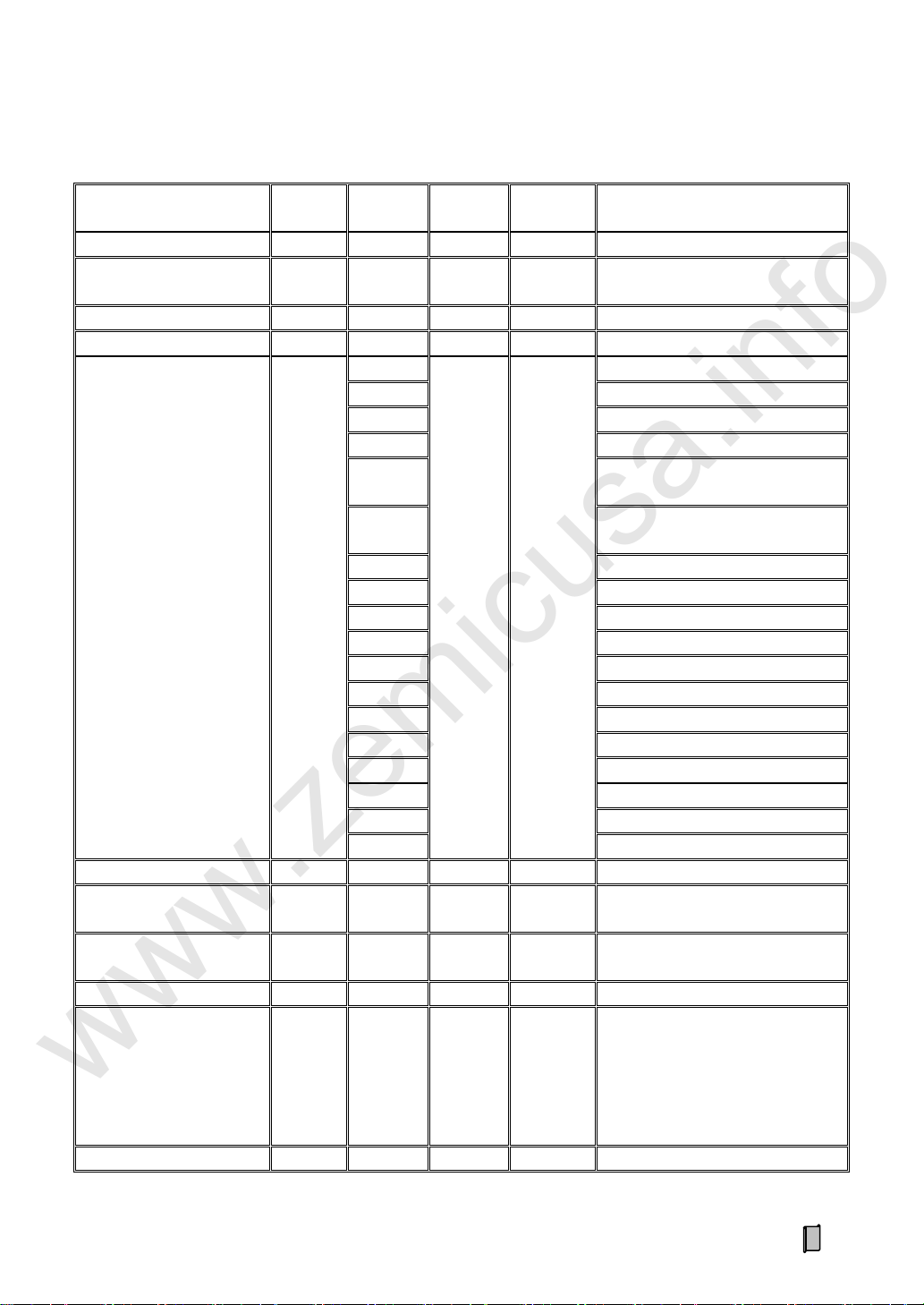
Appendix B. Register Table of Host-Slave MODBUS[ASCII]
Data Name
Type
Address
Attribute
Command
[HEX]
Description
Totalized Loading Weight
Long
40001 R 03
Single-bucket-
loading-weight
Long
40003 R 03
Bucket Count
Long
40005 R 03
Present Record No.
Long
40007 R 03
Alarm State
Long
40009.0
R
03
1: Stall Alarm.
40009.1
40009.2
1: Undertime Alarm.
40009.3
1: Overtime Alarm.
40009.4
1: Upper Limit Alarm of
Single-bucket-loading-weight.
40009.5
1: Lower Limit Alarm of
Single-bucket-loading-weight.
40009.6
40009.7
40009.8
40009.9
40009.10
40009.11
40009.12
40009.13
40009.14
40009.15
……
40009.31
Real-time Weight Value
Long
40011 R 03
Display Unit of Loading
Weight
Short
40013 R 03
Display Unit of Totalized
Loading Weight
Short
40014 R 03
Ton-Decimal
Short
40015 R 03
Bucket State
Short
40016 R 03
0: ▲[Loading].
1: ▲[1].
2: ▲[2].
3: ▲[3].
4-7: ▼.
8: ■[Pause].
Setpoint
Long
40017 R 03
www.zemicusa.info
37

Data Name
Type
Address
Attribute
Command
[HEX]
Description
Historical Record No.
Long
40019 W 10
For Record Query.
Historical Record Data
Packet
12-Short
40021
~40032
R
03
Char 1~8:
1: Second.
2: Minute.
3: Hour.
4: Day.
5: Month.
6: Week.
7: Year.
8: 14H [20D]
Char 9~12: Totalized Loading
Weight [Long]
Char 13~14: Bucket Count [Short]
Char 15~24: Goods [ASCII]
Note: „Char1=2DH‟ means „No
Record‟.
www.zemicusa.info
Record Query: Write the „Record No.‟ for query into the register [40019] at first, then read the whole data packet of the
registers [40021~40032].
38

User’s Memo
www.zemicusa.info
39

www.zemicusa.info
Changsha Supmeter Technological Co.,Ltd.
Address: Building A6, Lugu International Industrial Park,
Changsha, 410205, China
Tel: +86 731 85115100
Fax: +86 731 85158100
Website: www.supmeter.com.cn
E-mail: supmeter@163.com
 Loading...