


BST106-F19 Weighing Controller
For: Dynamic Axle Weigher
Operation Manual V7.2
Changsha Supmeter Technological Co.,Ltd.

1
Preface
Thank you very much for your purchase!
This manual covers safety precaution, technical specification, operation interface, installation&
connection, function&operation and so on. In order to make the product running at its best, please read this
manual in advance, and reserve it for the future reading.
The techno log y upd ate , funct io n enha nce me nt and qua lit y impr ove ment ma y lea d to so me di fference s
between this manual and the physical product, please understand.
Without our autho rization, the contents of this manual are not allowed to be copied and reproduced.
Main Features:
Suitable for Dynamic Axle Weigher (Max. axle count 99 and max. speed 10km/h).
EMC design with high anti-jamming capability, suitable for industrial environment.
6+10 green VFD digital tubes for for English character and digit display.
Optional English keypad, Simplified Chinese keypad and Complex Chinese keypad.
Menu&Shortcut mode operation with key tone.
24-bit High-precision and high-speed ∑-△A/D conversion module with 1/1,000,000 internal
resolution and sampling frequency 400Hz.
Special anti-vibration digital filtering algorithm for ensuring the weighing stability and accuracy
when there is str ong vibration on the load receptor, and the rapid response capability when the
weight signal changes.
Max. Con nection Quanti ty: 8 Loadcells (350Ω).
Auto Zero Initial Calibration after Power-on, Auto Zero Tracking, Zero Fine Adjustment, Zero
Calibration and Load Calibration functions available.
Optional Data Calibration function.
Auto-locking, Key-locking, Key-unlocking, Digital Setting&Calibration and I/O Testing
functions available.
1 Optional and definable analog signal output [AO: 4~20mA].
3 Normally open switch inputs [DI] and 5 normally open relay switch outputs [DO].
2 Optional communication ports for linking to Host IPC/PLC, LED Remote Display, Serial
Printer and Wireless Module.
The present axle weighing record can be printed automatically and manually.
The historical axle weighing records can be queried and printed.
With the multitasking mode, the weighing&control process will not be interrupted by parameter
setting and the other operations.
Model Panel-mounting: F19
Model Explosion-proof:F19EX

2
Contents
1. SAFETY PRECAUTION .................................................................................................................4
2. TECHNI CAL SPE CIFI CATION ....................................................................................................5
3. OPERATION INTERFACE ............................................................................................................7
3.1 MODEL PANEL-MOUNTING OPERATION INTERFACE ............................................................................... 7
3.2 MODEL EXPLOSION-PROOF OPERATION INTERFACE .............................................................................. 8
3.3 KEYPAD OPERATION.............................................................................................................................. 9
3.4 STATE INDICATION ............................................................................................................................... 10
3.5 ALARM SIGN ........................................................................................................................................11
4. INSTALLATION&CONNECTION ..............................................................................................12
4.1 INSTALLATION ..................................................................................................................................... 12
4.1.1 Model Panel-mounting Installation ........................................................................................... 12
4.1.2 Model Explosion-proof Installation ........................................................................................... 13
4.2 TERMINAL ........................................................................................................................................... 14
4.2.1 Model DC24V Terminal ............................................................................................................ 14
4.2.2 Model AC85~264V/AC220V T ermin al ..................................................................................... 14
4.3 DO/DI FUNCTION DEFINITION ............................................................................................................ 18
4.4 DO/DI CONNECTION FOR TYPLE APPLICATION ................................................................................... 19
5. OPERATION PROCEDURE ........................................................................................................20
6. FUNCTION&OPERATION ..........................................................................................................21
6.1 MAIN DISPLAY INTERFACE .................................................................................................................. 21
6.1.1 Gross/Net Weight, Axle No. / Axle Count, Axle Weight / Total Axle Weight [TOT] ................ 21
6.1.2 Gross/Net Weight, AO Output Value [Ao] ................................................................................ 22
6.2 MAIN MENU ........................................................................................................................................ 23
6.3 F1-SET PARAMETER SETTING ............................................................................................................. 25
6.3.1 Weighing Parameters (SCAL) ................................................................................................... 25
6.3.2 Calibration Parameters ( CALP)................................................................................................. 27
6.3.3 Setpoint Parameters (SEtP) ....................................................................................................... 29
6.3.4 Communication Parameters (SErP) ........................................................................................... 31
6.3.5 Display Parameters (dISP) ........................................................................................................ 33
6.3.6 Time Parameter (tIEE) ............................................................................................................... 33
6.3.7 A Sample of Parameter Setting .................................................................................................. 34

3
6.4 F2-CAL SYSTEM CALIBRATION .......................................................................................................... 35
6.4.1 Zero Calibration (ZEro) ............................................................................................................. 35
6.4.2 Data Calibration (dAtA) ............................................................................................................ 36
6.4.3 Load Calibration (LoAd) ........................................................................................................... 38
6.5 F3-REC RECORD QUERY .................................................................................................................... 39
6.6 F4-CLN DATA CLEARING ................................................................................................................... 40
6.7 F5-LOC KEY-LOCKER ......................................................................................................................... 41
6.7.1 Key-unlocking (oP En) ............................................................................................................... 41
6.7.2 Key-locking (Locc) ................................................................................................................... 41
6.7.3 Password Set (PASS) ................................................................................................................. 42
APPENDIX A. PRINT FORMATS ...................................................................................................43
APPENDIX B. REG ISTER TABLE OF HOST-SLAVE MODBUS[ASCII/RTU] ........................44
APPENDIX C. DATA FRAME FORMA T OF CONTINUOUS SENDING [ASCII] ....................47

4
1. Safety Precaution
Lithium Battery I nstallation
A Lithium batter y should be equipped in th e product. If it is not allowed to be transported
together with the product because of embargo, please make a purchase according to the
model offered by us and install it by yourself.
Application environment
Make sure that this product w orks under the environment where is accord with th e technical
specifications. Do not open the shell before power-off.
Avoid using the product under overheated environment
Make sure that the produc t works under the environment with allowed tem perature r ange to
get good performance and long working life.
Please keep the produc t awa y from dir ect sunli ght. If it is installed in a cabinet, pleas e install
cooling fans on the top of the cabinet.
Controller Grounding Protection
The product, as a low-voltage equipment, should be kept away from the high-voltage
equipments.
For avoiding bodily injury from electric shock accident and keeping the product separate from
strong interference, the metal shell of the product should be grounded directly and the ground
resistance should be less than 4Ω.
Scale Frame Grounding Protection
For avoiding bodily injury from electric shock accident and keeping the loadcells separate
from strong interference, the scale frame should be connected with the electronic scale
grounding net and the ground resistance should be less than 4Ω.
Cable Laying
Weighing signal, analog sig nal a nd c om munication signal cables should be laid in pipes, and
do not lay them together with power cables.
Power Supply
Please make sure that the inputted voltage is correct before power-on.
If the voltage fluctuation ex ceeds the allowed range, please use a power stabilizer to get a
stable voltage supply.
Environmental Protection
Before the Lithium battery equipped in the product being discarded, please insulate its
positive or negative pole, do not put it into fire.
Although the product is made of the lead-free components, after used in the industrial
environments, it’s possible to be polluted. So, while being discarded as worthless, the product
should be processed lawfully as leady industrial waste for environment protection.
Other Notes
The installation, wiring and maintenance should be operated by the engineers with the
relevant professional knowledge and safety operation ability. Although being not described in
this manual, the relevant safety operating procedures and standards should be followed.

5
2. Technical Specification
Executing Standard
CMC GB/T 7724-2008《Electronic Weigh ing Meter》PRC National Standard.
OMIL R76: 2006《Non-automatic Weighing Instruments》International Recommendation.
Accuracy Grade: III .
Number of Verification Intervals: 5,000.
Static Weighing Accuracy: 0.2‰.
Display
6+10 Green VFD digital tubes for for English character and digit display.
Weight Display Range: -99,999~+999,999.
Scale Capacity: Setting Range 1~999,999.
Scale Division: Op tional 1, 2, 5, 10, 20, 50, 100, 200, 500.
Display Resolution: 1/100,000.
Weight Unit: Optional kg, t, g, none.
Decimal Point: Optional 0, 0.0, 0.00, 0.000, 0.0000.
Display Refreshing Time: Se t ting Range 0. 01~1.00s.
Kaypad
Optional 8-key English keypad, Simplified Chinese keypad and Complex Chinese keypad.
Menu&Shortcut mode operation with key tone.
Loadcell Interface
Excitation Voltage/Max. Curre nt : DC10V/250mA [8-350Ω loadcells].
Signal Input Range: 0~25mV.
Output Sensitivity of Loadcell: 1.0~2.5mV/V.
24-bit ∑-△ADC with internal resolution 1/1,000,000.
Sampling Frequency: 400Hz.
Special anti-vibration digital filtering algorithm.
Zero Drift: ±0.1μV/℃ RTI (Relative to Input).
Gain Drift: ±5ppm/℃.
Non-linearity: 0.005%FS.
Switch&Analog S ignal Interface
3 Normally Open Switch Inputs [DI].
5 Nor mally Open Relay Switch Outputs [DO]: AC250V/DC24V, 1A.
1 Optional&Definable Analog Signal Output [AO]: 4~20mA, Non-linearity: 0.05%FS.
Digital Communication Interf a c e
COM1: Fixed configuration RS232&RS485. Free to use one of them.
COM2: Optional RS232/RS485/RS422/Profibus-DP/Ethernet modules.
Connectable: Host IPC/PLC, LED Remote Display, Serial Printer and Wireless Module.

6
Report Print
The present axle weighing record can be printed automatically and manually.
The historical axle weighing records can be queried and printed.
Operating Specification
Optional Operating Voltage
Operating Voltage 1: DC24V±20%.
Operating Voltage 2: AC85~264V, 50/60Hz.
Operating Voltage 3: AC220V±15%, 50/60Hz.
Free to configure one of them.
Max. Power Consumption: 10W.
Outline Size
Model Panel-mounting: 164×82×188mm [W×H×D].
Model Explosion-proof: 340×390×205mm [W×H×D].
Panel Cut-out Size
Model Panel-mounting: 153×77mm [W×H].
Operating Temperature: -25℃ to +40℃.
Storage T emperature: -30℃ to +60℃.
Relative Humidity: Max. 85%RH.
Application Environment of Model Explosion-proof
Explosion gas environment: Zone 1&2.
Classes of explosion gas mixture: IIA, IIB.
Temperature grades of explosion gas mixture: T1~T6.
Ex-mark: Ex d IIB T6 Gb.
Protection Level
Front Panel of Model Panel-mounting: IP65.
Model Explosion-proof: IP65.
Weight
Model Panel-mounting: Approx. 1.6kg.
Model Explosion-proof: Approx. 19.2kg.

7
3. Operation Interface
3.1 Model Panel-mounting Operation Interface
F1
±
→C←
CAL
→0←
ZERO
∧
→T←
TARE
∨
∑
ENT
G/N
>
MENU
SET
<
RUN
NUM
PCS
TOT
SET
GROSS
NET
SUM
LOCK
SUPMETER
ZERO NZ SP1 SP2 SP3
FILL COMP DEV FALL PACK DISC
HH HI
LO
LL
0

8
3.2 Model Explosion-proof Operation Interface
RUN
NUM
PCS
TOT
SET
GROSS
NET
SUM
LOCK
SUPMETER
ZERO NZ SP1 SP2 SP3
FILL COMP DEV FALL PACK DISC
HH HI
LO
LL
0
F1
±
G/N
►
MENU
SET
◄
∑
ENT
→T←
TARE
▼
→0←
ZERO
▲
→C←
CAL

9
3.3 Keypad Operation
If there is not any keypad operation in one minute and it’s not in the processes of ‘F2 Calibration’ & ‘F6 Factory
Adj.’, the controller will return to ‘Main Display Interface’ automatically.
*: Keep the key pressed for 2 seconds.
Menu Operation
Key Name Description
【MENU】 Enter Main Menu / Exit.
【ENT】 Enter / Save / Alarm Acknowledge.
【◄】
Cursor shifts left.
【►】 Cursor shifts right.
【▲】
Display the previous interface or option.
Digit input: +1.
【▼】
Display the next interface or option.
Digit input: -1.
Quick Operation
【
】
*
Key-locking.
Key-unlocking.
【SET】 Setpoint parameters setting.
【G/N】 Gross Weight / Net Weight display switch.
【→C←】
【CAL】
*
Load Calibration.
【→0←】
【ZERO】
*
[-ZEro-]: Zero Calibration with Power-down Protection and Clearing Tare Weight.
[≡ZEro≡]: Zero Fine Adjustment without Power-down Protection and without Clearing
T are Weight.
The controller will switch to Gross Weight display.
【→T←】
【TARE】
*
[≡tArE≡]: Manual Tare without Power-down Protection.
[-PStr-]: Preset Tare Weight with Power-down Protection.
[-rStr-]: Clear Tare Weight wit h Power-down Protection.
The controller will switch to Net Weight display.
【
】* Record Query.
【】
*
Clear Screen:
C lear the display value of Axle Count and Total Axle Weight.
Cear Alarm.
Cancel the present axle weighing process.
【
】* Time display and setting.
【
±
】 ‘+’/‘-’ switch.
【】
Main Display Interface: Print Present Axle Weighing Record.
R ecord Query State: Print Historical Axle Weighing Record.
【∑】
Stop Axle Weighing Process & Print: After the present axle has been weighed, the axle
weighing process will end and the Axle Weighing Record will be printed.

10
3.4 State Indication
Sign Description
[GROSS] Gross Weight display.
[NET] Net Weight display.
[LOCK]
ON: Key-locked.
OFF: Key-unlocked.
[◣◢]
Weight is stable: Weight Variance per [107] ‘Stablity Judging Time’ is in [106] ‘Stablity
Judging Range’.
[→0←]
The present Gross Weight or Net Weight display value is in ‘Display Value Auto-Zero
Range.
[kg/t/g] Weight unit.
[ NUM] Axle No. or Axle Count display.
[TOT] Total Axle Weight display.
[SET] Parameter setting state.
[RUN]
ON: Axle W eighing state.
OFF: Waiting or Calibrating state.
[ZERO] Net Weight value ≤ Non-load Zero Range [Min. Valid Axle Weight].
[NZ] It’s allowed to do Zero Fine Adjustment.
[FILL] Weigh t value is increasing [An axle is entering the weighing platform].
[COMP] Permit to do axle identification by DI switch.
[DISC] Weight value is reducing [An axle is exiting from the weighing platform].
[HH] Total Axle Weight Upper Limit Alarm.
[HI] Axle Weight Upper Limit Alarm .

11
3.5 Alarm Sign
Sign Alarm Cause Solution
Err1 RAM Failure. Replace the chip RAM.
Err2.1
Err2.2
EEPROM Failure. Replace the chip EEPROM.
Err3
Signal Reversed.
Not connected.
Connect the loadcel l correctly.
Err4 ADC Failure. Replace the ADC module.
oV-Ad Over ADC Range.
Weigh ing signal exceeds A/D conversion range.
1. Check if the loadcell is connected.
2. Check if the capacity of loadcell is too small.
3. Check if the loading weight is too big.
oL Overload Alarm.
Gross Wei ght > (Scale Capacity + 9 × Scale Division).
1. Check if the loadcell is connected.
2. Check if the capacity of loadcell is too small.
3. Check if the loading weight is too big.
oV-tr
Not meet the condition of
Maunal Tare.
When Gross Weight is at the state with negative value display,
overload alarm or dynamic variation, ‘Manual Tare’ will be
invalid.
oV-nZ
Over
‘Zero Fine Adjusting
Range’.
Refer to parameter [1 23] ‘Zero Fine Adjusting Range’.
HEAt
Preheating Time Countdown
[min.sec].
Refer to parameter [128] ‘Auto Zero Initial Calibration after
Power-on’, [129] ‘Auto Zero Initial Calibrating Time’ and
[130] ‘Auto Zero Initial Calibrating Range’.
Wait for the preheating time over or press any key to exit.
oV-Zr
Over ‘
Auto Zero Initial
Calibrating Range’.
Prt-undEF Print port is not defined. Refer to ‘Communication Parameters’.

12
4. Installation&Connection
4.1 Installation
4.1.1 Model Panel-mounting Installation
Outline Size
W×H×D[mm]
Front Panel Size
W×H[mm]
Box Body Size
W×H[mm]
Panel Cut-out Size
W×H[mm]
164×82×188 164×82 152×76 153×77
Installation Mode
153
77
Panel Cut-out Size
Outline Size Front Panel Size
188
82
164
(76)
(152)

13
4.1.2 Model Explosion-proof Installation
Outline Size
W×H×D[mm]
Mounting Size
W×H[mm]
Mounting Hole Size
[mm]
340×390×205 288×230 Ф11
14
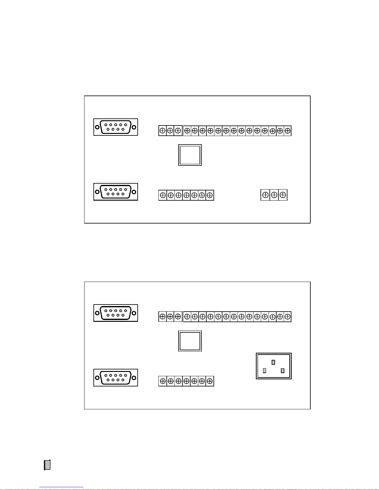
4.2 Terminal
4.2.1 Model DC24V Terminal
4.2.2 Model AC85~264V/ AC220V Terminal
ETHERNET
POWER
N
L
E
LOADCELL
SIG-
SIG+
EXC-
SEN-
EXC+
SEN+
SHD
DO/DI
DO1+
DO1-
DO2+
DO2-
DO3+
DO3-
DO4+
DO4-
DO5+
DO5-
COM
DI1
DI2
DI3
AO
AO+
AO-
SHD
COM1
COM2
ETHERNET
LOADCELL
SIG-
SIG+
EXC-
SEN-
EXC+
SEN+
SHD
DO/DI
DO1+
DO1-
DO2+
DO2-
DO3+
DO3-
DO4+
DO4-
DO5+
DO5-
COM
DI1
DI2
DI3
AO
AO+
AO-
SHD
COM1
COM2
POWER
DC-
DC+
PG

15
No. Pin Description
LOADCELL Loadcell Port
Connection Mo de 6-Wire 4-Wire
Internal Dip Switch DIP1 DIP1→【6-WIRE】
DIP1→【4-WIRE】
[Default Set]
1 SIG- Weighing Signal [mV] Input -. Weighing Signal [mV] Input -.
2 SIG+ Weighing Signal [mV]Input +. Weighing Signal [mV] Input +.
3 EXC- Excitation Voltage -. Excitation Voltage -.
4 SEN- Feedback Voltage -.
5 EXC+ Excitation Voltage + [DC10V]. Excitation V ol tage + [DC10V].
6 SEN+ Feedback Voltage +.
7 SHD Shield Ground. Shield Ground.
POWER Power Input Port
DC24V DC24V[±20%] Power Input
1 DC- DC Input -.
2 DC+ DC Input +.
3 PG P rotective Ground.
AC AC85~264V or AC22 0V[±15%] Power Input
1 N Null Wire.
2 E Protective Ground.
3 L Live Wire.
The metal shell should be grounded directly to avoid electric shock.

16
No. Pin Description
COM1
RS232/RS 485 Digital Communication Port
[Free to use one of them]
DB9 Socket RS232 RS485
1 B- Data -.
2 A+ Data +.
3
4
5 GND Signal Ground / Shield Ground. Shield Ground.
6 TXD Transmit Data.
7 RXD Receive Data.
8
9 +5V +5V/100mA Output. +5V/100mA Output.
No. Pin Description
COM2
RS232/RS485/RS422/Profibus-DP/Ethernet Digital Communication Port
[It's optional to configure one of them]
DB9 Socket RS232 RS485 RS422 Profibus-DP
1 B- TXD-
2 RXD A+ TXD+
3 TXD RXD+ DP- [B-]
4 RXD-
5 GND GND GND GND
6
7
8 DP+ [A+]
9
RJ45[DCE] Socket
Ethernet
[T568B Wiring Mode]
1 RXD+ Orange-white
2 RXD- Orange
3 TXD+ Green-white
4 Unused Blue
5 Unused Blue-white
6 TXD- Green
7 Unused Brown-white
8 Unused Brown

17
No. Pin Description
AO Anal o g Output Port [Definable]
1 AO+ 4~20mA Output +.
2 AO- 4~20mA Output -.
3 SHD Shield Ground.
DO/DI Relay Sw itch Signal Output / Switch Signal Input Port
DO Relay Switch Signal Output [Definable]
1 DO1+
Normally Open Contact Output 1 [+/-].
2 DO13 DO2+
Normally Open Contact Output 2 [+/-].
4 DO25 DO3+
Normally Open Contact Output 3 [+/-].
6 DO37 DO4+
Normally Open Contact Output 4 [+/-].
8 DO49 DO5+
Normally Open Contact Output 5 [+/-].
10 DO5-
DI Sw itch Signal Input
11 COM DI Common Terminal [GND].
12 DI1 Switch Signal Input 1.
13 DI2 Switch Signal Input 2.
14 DI3 Switch Signal Input 3.
Contact Capacity of Relay Switch: AC250V/DC24V, 1A.

18
4.3 DO/DI Function Definition
Note: Whether to do Axle Identification by switch DI1 or not is decided by the parameter “[205] dI1.Id”.
No. Pin Sign al Name Description
1 DO1+
RUN Axle Weighing State.
2 DO13 DO2+
FINI Axle Weighing Process Finished.
4 DO25 DO3+
HH Total Axle Weight Upper Limit Alarm.
6 DO37 DO4+
HI Axle Weight Upper Limit Alarm.
8 DO49 DO5+
ZERO Non-load Zero Range.
10 DO511 COM COM DI Common Terminal [GND].
12 DI1 AXLE_ID
Axle Identification.
ON: There is an axle entering t he weighing platform.
13 DI2 TARE
Manual Tare.
OFF→ON→OFF.
14 DI3
【∑】
Axle Wei ghing State: Stop Axle Weighing Pro cess & Print
(After the present axle has been weighed, the weighing
process will end and the Axle Weighing Record will be
printed).
OFF→ON→OFF.
【】
Waiting State: Print the present Axle Weighing Record.
OFF→ON→OFF.

19
4.4 DO/DI Connection for Typle Application
Weighing Platform
V≤10km/h
A1~A99
A1 A2
…
An
Summing Box
Optional Axle Identification DI Switch
COM
DI1
DI2
DI3
Push Button
Switch
DI Common Terminal
Axle Identification AXLE_ID
Maunal Tare TARE
Stop Axle Weighing Pro ces s / Print
Axle Weighing State
RUN
Axle Weighing Process Finished
FINI
Total Axle Weight Upper Limit
HH
Axle Weight Upper Limit
HI
Non-load Zero Range
ZERO
AC220V or DC24V
DO1+
DO1-
DO2+
DO2-
DO3+
DO3-
DO4+
DO4 -
DO5+
DO5-
DO [Realy]
DI

20
5. Operation Procedure
Connection & Power on
Zero Calibration
Other Settings
Key-locking
Scale Setting
Auto Zero Tracking Range &
Zero Fine Adjusting Range Setting
Setpoint Setting
[Data Calibration]
Load Calibration

21
6. Function&Operation
6.1 Main Display Interface
【▲】【 ▼】: Display interface switch.
6.1.1 Gross/Net W eight, Axle No. / Ax le Count, Axle Weight / Total Axle Weigh t [TOT]
RUN
NUM
PCS
TOT
SET
GROSS
NET
SUM
LOCK
SUPMETER
ZERO NZ SP1 SP2 SP3
FILL COMP DEV FALL PACK DISC
HH HI
LO
LL
0
In the Axle Weighing process, display:
RUN
NUM
PCS
TOT
SET
GROSS
NET
SUM
LOCK
SUPMETER
ZERO NZ SP1 SP2 SP3
FILL COMP DEV FALL PACK DISC
HH HI
LO
LL
0
Axle Count [E00~E99] & Total Axle Weight.
T otal Axle W eig ht will be kept displaying till the next axle weighing
process started.
After the axle weighin g process, display:
Axle No. [A01~A99] & Axle Weight.
After Axle 99 has been weighed, the weighing process will end.

22
6.1.2 Gross/Net Weight, AO Output Value [Ao]
RUN
NUM
PCS
TOT
SET
GROSS
NET
SUM
LOCK
SUPMETER
ZERO NZ SP1 SP2 SP3
FILL COMP DEV FALL PACK DISC
HH HI
LO
LL
0
AO: 4.00~20.00mA.

23
6.2 Main Menu
Main Menu Second Menu
Sign Function Sign Description
F1-SEt
Parameter
Setting
-SCAL- Scale parameters setting.
-CALP- Calibration parameter setting.
-SEtP- Setpoint parameters setting.
-SErP- Communication parameters setting.
-dISP- Display and oper ation interface parameters setti ng.
-tIEE- Time parameters setting.
F2-CAL
System
Calibration
-ZEro-
Zero Calibration without loading on the weigher to correct Zero
Value.
-dAtA-
Data Calibration: Input the specification parameter values of loadcell
[Total Capacity and Output Sensitivity] according to the actual
configuration
of the weighing system to correct Span Coefficient. If
there is no access to get the specificat ion parameter values for Data
Calibration, then it’s necessary to do Load Calibration.
-LoAd-
Load Calibration: After doing Data Calibration, if there are
conditions for Load Caliration, do Load Caliration with loading
standard weight on the weigher to correct Span Coefficient further for
higher weighing accuracy.
F3-rEC
Record
Query
Record Query.
F4-CLn
Data
Clearing
--CLS-
Clear Screen:
C lear the display value of Axle Count and Total Axle Weight.
C ancel the present axle weighing process.
--CLr- Clear Records: Clear all of the axle weighing records.
F5-Loc Key-locker
-oPEn- Key-unlocking.
-Locc- Key-locking.
-PASS-
Password Set.
Exfactory Passwords:
Operator Passwor d: 000000.
Administrator Pas s word: 000001.

24
Main Menu Second Menu
Sign Function Sign Description
F6-FAC
Factory
Adjustment
Special for manufactur er.
-SPAn-
Exfactory Span Adjustment: Use standard weighing test equipment to
adjust the weighing signal interfa ce for normalizing Span Coefficien t
to 1.
-AdtS- AD Value of Weighing Signal Linearity Test.
-AoZF- AO Zero/Full Adjustment.
-AotS- AO Linearity Test.
-dIdo- DI/DO Input&Output Te st.
-dEFU- RAM Reset : Reset to factory defaults.
-dStS- Display/DO Reliability Test.
F7-InF
Product
Information
Only for query.
--VEr- Vers ion No.
--Sn-- Serial No.
-dAtE- Exfactory Date.
-AutH- Authorization Code.
F8-Aud Audit Trail
Only for query.
-Cntr- Operation A udit Trail Counter [0~999999].
-oPtr-
Operation T ra il.
nonE: No Operation.
SCAL: Scale Setting.
CLr: Clear Records.
dEFU: RAM Reset.

25
6.3 F1-SET Parameter Setting
6.3.1 We ighing Parameters (SCAL)
No. Sign Range Default Description Set
100 UnIt 0~3 2
Weight Unit
0: None
1: kg
2: t
3: g
101 dot 0~4 ooo.oo
Decimal Point
0: ooooo
1: oooo.o
2: ooo.oo
3: oo.ooo
4: o.oooo
102 SCALE 1~999999 2000
Scale Capacity
Max. loading weight of the load receptor.
Scale Capacity≤ (Loadcell Capacity × Loadcell
Quantity) – Load Receptor Weight.
When ‘Weight value = Scale Capacity’, AO of
weight signal will output current 20mA.
103 dIV 1~500 1
Scale Division
1, 2, 5, 10, 20, 50, 100, 200, 500
104 ZEro
-20000~
+999999
0
[*]
Zero Value
Only for query.
105 SPAn >0
1.0000
[*]
Span Coefficient
Max. display value: 99.9999.
Only for query.
106 Stb.r 0~500 1
Stablity Judging Range [Division]
Set value = 0: No ‘Stablity Judging’.
Set value > 0: Weight Variance per [107] ‘Stablity
Judging Time’ being in [106] ‘
Stablity Judging
Range’ means ‘Weight is stable’.
107 Stb.t 0.5~5.0 1.0 Stablity Judging Time [s]
[*]: ‘RAM Reset’ operation has no effect on the parameter.

26
No. Sign Range Default Description Set
108 FrE 400 400
Sampling Frequency [Hz]
400
109 FILt 0~9 5
Anti-Vibration Digital Filter
Digit Cutoff Frequency
0 None
1
80Hz
2
56Hz
3
40Hz
4
28Hz
5
20Hz
6
14Hz
7
10Hz
8
7Hz
9
5Hz
110 StAb 2~20 10
Sample Number for Axle Weight Stablity
Judgement

27
6.3.2 Calibration Parameters (CALP)
No. Sign Range Default Description Set
120 AZt.P 0~1 0
Auto Zero Tracking Permission
0: oFF
1: on (Only when weight is stable, Auto Zero
Tracking will be allowed. Refer to Parameter
[106]/[107])
121 AZt.t 1~10 1
Auto Zero Tracking Time T [s]
T = Set value × [107] Stablity Judging Time.
122 AZt.r 0.1~50.0 0.2
Auto Zero Tracking Range [Division]
Zero Tracking Rate = [122] / [121].
Suggestion: Zero Tracking Rate ≤ 0.5[Division/s].
123 nEAr.Z 0~50000 50
Zero Fine Adjusting Range
If Gross Weight variation caused by
Zero Value
changing is within this range, ‘
Zero Fine
Adjustment’ will be valid.
Suggestion: Set value ≤ (Scale Capacity × 4%).
124 LoAd 1~999999 10000
Calibrating Weight
Loading Weight for Span Calibration.
125 totL 1~999999
12000
[*]
Total Capacity of Loadcells
To tal Capacity of Loadcells = Loadcell Capacity ×
Loadcell Number.
Only for query.
126 SEnS
0.5000
~5.0000
2.0000
[*]
Output Sensitivity of Loadc e ll [mV/V]
Only for query.
127 Ao.Er -2.00~+2.00 0.00
AO Offset Value [mA]
Try to change ‘AO Offset Val ue’ for making the AO
current display valu e of the AO receiving terminal
the same as that of the controller.
If t
he AO current display value of the AO receiving
terminal is smaller than that of the controller
because of signal attenuating, the ‘AO Offset Value’
should be set to positive value.
If the AO current display value of the AO re ceiving
terminal is bigger than that of the controller because
of interference signal superposing, the ‘AO Offset
Value’ should be set to negative value.
【±】: Optional ‘ -’ (negative sign) at the highest bit.
[*]: ‘RAM Reset’ operation has no effect on the parameter.

28
No. Sign Range Default Description Set
128 InI.Z 0~1 0
Auto Zero Initial Calibration after Power-on
0: oFF
1: on [without Power-down Protection]
129 InI.t 0~1800 10 A uto Zero Initial Calibrating Time [s]
130 InI.r 0~50000 50
Auto Zero Initial Calibrating Range
Suggestion: Set value ≤ (Scale Capacity × 20%).

29
6.3.3 Setpoint Parameters (SEtP)
No. Sign Range Default Description Set
200 VALId 1~999999 20
Non-load Zero Range [Min. V alid Axle W eight]
Essential condition of triggering the axle weighing
process: Net Weight > Min. Valid Axle W eight.
Optional condition of triggering axle weighing: DI1
Axle Identification Switch turns on.
201 HoLd.t 5~999 30
Allowable Holding Time of Valid Axle Weight [s]
When holding time of valid axle weight is bigger
than this set value, the axle weighing process will
be invalid.
202 End.tI 5~999 10
Auto-end Time [s]
After the previous axle has been weighed:
After this time delayed, if there is no new axle
enter into the weighing platform, the axle
weighing process will end and the weighing
record will be printed automatically.
In this time, if key【∑】is pressed, the axle
weighing process will end and the weighing
record will be printed automatically.
203 tot.H 1~999999 10000
Total Axle Weight Upper Limit
When ‘Total Axle Wei ght > Set Value’, DO switch
‘Total Axle Weight Upper Limit’ will
turn on
automatically.
204 nEt.H 1~999999 1800
Axle We ight Upper Limit
When ‘Axle Weight > Set Value’, DO switch ‘Axle
Weight Upper Limit’ will turn on autom a tica lly.
205 dI.Id 0~1 0
Axle Identification by Input Switch DI1
0: oFF
1: on
206 do.SL 0~1 0
DO Output Permission
0: oFF
1: on

30
No. Sign Range Default Description Set
207 Ao 0~3 3
AO Signal
0. groS [Gross W eight]
1. nEt [Net Weight]
2. dISP [Displayed Weight]
3.AnEt [Axle Weight]
208 Au.Prt 0~1 1
Auto Print
0: oFF
1: on [It’s necessary to define print port]
Refer to Appendix A.
209 Prt.F 1~2 1
Print Format
1: Format 1
2: Format 2

31
6.3.4 Communication Parameters (SErP)
No. Sign Range Default Description Set
800 Adr 0~99 1 Communication Address
801
802
bPS1
bPS2
0~5
3
3
COM1/COM2 Baud Rate
0:
1200bps
1
:
2400bps
2
:
4800bps
3
:
9600bps
4
:
19200bps
5: 115200bps
803
804
CHC1
CHC2
0~2
0
0
COM1/COM2 Parity Check
0. none [None Check]
1. EVEn
[Even Check]
2. odd
[Odd Check]
805 Con1 0~6 3
COM1 Communication Mode
0. HASC
[Host-slave, Modbus ASCII]
1. Hrtu
[Host-slave, Modbus RTU]
2. Cont
[Continuous Sending ASCII]
3. Prt
[Print]
4. USE1
[User1]
5. USE2
[User2]
6. USE3
[Host-slave, BWT Netherlands]
806 Con2 0~6 2
COM2 Communication Mode
0. HASC [Host-slave, Modbus ASCII]
1. Hrtu
[Host-slave, Modbus RTU]
2. Cont
[Continuous Sending ASCII]
3. dP-C
[Modicon Profibus-DP]
4. dP-S
[Siemens Profibus-DP]
5. Prt
[Print]
6. USE3
[Host-slave, BWT Netherlands]
807 dAtA 0~3 2
Data for Continuous Sending Mode
0. groS [Gross We ight]
1. nEt [Net Weight]
2. dISP
[Displayed Characters]
3. tot [Total Axle W eight]

32
No. Sign Range Default Description Set
808 S.Int 4~400 80
Continuous Sending Interval Number N
Sending Interval T ime: T = N
× 2.5 [ms].
Sending Frequency: F = 1000 / T [Hz].
Examples
Interval Number N Sending Frequency F
4 100Hz
8 50Hz
10 40Hz
40 10Hz
80 5Hz
100 4Hz
400 1Hz
Note
Baud Rate Max. Sending Frequency
1200bps 5Hz
2400bps 10Hz
4800 bps 25Hz
9600 bps 50Hz
19200 bps 100Hz
115200 bps 100Hz
809 dAt.F 0~3 0
Modbus Data F ormat
Reading&Writing Order of 4-Byte Registers:
0: 4321 [HB4 HB3 LB2 LB1]
1: 3412 [HB3 HB4 LB1 LB2]
2: 1234 [LB1 LB2 HB3 HB4]
3: 2143 [LB2 LB1 HB4 HB3]
The HEX byte order of float and long int registers
in the weighing controller is ‘HB4 HB3 LB2 LB1’.

33
6.3.5 Display Parameters (dISP)
No. Sign Range Default Description Set
900 LAng 0~1
0/1
[*]
Printing Language
0. CHn [Chinese]
1. Eng [English]
901 dS.tI 0.01~1.00 0.20 Display Refreshing Time [s]
902 Au.Loc 0~1 0
Auto-Locking
0: oFF
1: on
[ If there is not any keypad operation in
one minute and it’s not in the processes of ‘F2
Calibration’ & ‘F6 Factory Adj.’, the controller will
lock the keypad and return to ‘
Main Display
Interface’ automatically ]
903 dAtE 0~2
0
[*]
Date Format
0: yy. EE. dd [Year. Month. Day]
1: EE. dd. yy [Month. Day. Year]
2: dd. EE. yy [Day. Month. Year]
904 FAn.r 0~1 1
Cooling Fan Running
0. oFF
1. on
[*]: ‘RAM Reset’ operation has no effect on the parameter.
6.3.6 Time Parameter (tIEE)
No. Sign Range Default Description Set
998
Local
Time
HH[Hour]. MM[Mintus]. SS[Second]
[903] Date Format - W[Week]
[W=7: Sunday]

34
6.3.7 A Sample of Parameter Setting
Modify the parameter ‘[102] Scale Capacity’.
RUN
NUM
PCS
TOT
SET
GROSS
NET
SUM
LOCK
SUPMETER
ZERO NZ SP1 SP2 SP3
FILL COMP DEV FALL PACK DISC
HH HI
LO
LL
0
RUN
NUM
PCS
TOT
SET
GROSS
NET
SUM
LOCK
SUPMETER
ZERO NZ SP1 SP2 SP3
FILL COMP DEV FALL PACK DISC
HH HI
LO
LL
0
【MENU】: Exit 【ENT】: Save
M
M
Main Display Interface
【MENU】+【▲】【 ▼】: F1-SEt
【ENT】+【▲】【 ▼】
【ENT】+【▲】【 ▼】
【ENT】
【◄】【 ►】: Moving cursor; 【▲】【 ▼】: Digit input.
RUN
NUM
PCS
TOT
SET
GROSS
NET
SUM
LOCK
SUPMETER
ZERO NZ SP1 SP2 SP3
FILL COMP DEV FALL PACK DISC
HH HI
LO
LL
0

35
6.4 F2-CAL System Calibration
After doing ‘System Calibration’, Tare Weight value will return to zero automatically.
6.4.1 Zero Calibration (ZEro)
Do Zero Calibration with no loading on the weigher and save the new Zero Value.
RUN
NUM
PCS
TOT
SET
GROSS
NET
SUM
LOCK
SUPMETER
ZERO NZ SP1 SP2 SP3
FILL COMP DEV FALL PACK
HH HI
LO
LL
0
DISC
Main Display Interface
【MENU】+【▲】【 ▼】: F2-CAL
【ENT】+【▲】【 ▼】: -ZEro【
ENT】
M
【MENU】: Exit 【ENT】: Save
M
【▲】【 ▼】:
104: New Zero Value (-20000~+999999).
oLd: O
riginal Zero Value.
Er: Error = New Value - Original Value.
If Zero Val ue exceeds allowed ra nge, [SET] will tu rn off, and it’s not
allowed to save Zero Value.

36
6.4.2 Data Calibration (dAtA)
Input the specification parameter values o f loadcell [Total Capacity and Output Sensitivity] according
to the actual configuration of the weighing system to correct Span Coefficient. If there is no access to get
the specification parameter values for Data Calibration, then it’s necessary to do Load Calibration.
RUN
NUM
PCS
TOT
SET
GROSS
NET
SUM
LOCK
SUPMETER
ZERO NZ SP1 SP2 SP3
FILL COMP DEV FALL PACK
HH HI
LO
LL
0
DISC
RUN
NUM
PCS
TOT
SET
GROSS
NET
SUM
LOCK
SUPMETER
ZERO NZ SP1 SP2 SP3
FILL COMP DEV FALL PACK
HH HI
LO
LL
0
DISC
Main Display Interface
【MENU】+【▲】【 ▼】: F2-CAL
【ENT】+【▲】【 ▼】: -dAtA【
ENT】
M
Input ‘Total Capacity of Loadcells’ [totL]: 1~999999 Weight Unit.
【ENT】
Input ‘Output Sensitivity of Loadcell’ [SEnS]: 0.5000~5.0000mV/V.
【ENT】
RUN
NUM
PCS
TOT
SET
GROSS
NET
SUM
LOCK
SUPMETER
ZERO NZ SP1 SP2 SP3
FILL COMP DEV FALL PACK
HH HI
LO
LL
0
DISC
Input ‘Voltage Ratio’ [VoL.r]: 1.0000~2.0000.
【ENT】

37
Note:
Total Capacity of Loadcells = Lo adcell Capacity × Loadcell Number.
Voltage Ratio = Excitation Voltage on the terminal of controller / Excitation Voltage on the terminal of
loadcells.
The rated excitation voltage for loadcells is DC10V. It’s best to measure the actual voltage value.
4-wire connection: Th e voltage attenuation is big, the voltage on both sides should be measured.
6-wire connection: Th e voltage attenuation is small, Voltage Ratio can be set to 1.0000.
RUN
NUM
PCS
TOT
SET
GROSS
NET
SUM
LOCK
SUPMETER
ZERO NZ SP1 SP2 SP3
FILL COMP DEV FALL PACK
HH HI
LO
LL
0
DISC
【MENU】: Exit 【ENT】: Save
M
【▲】【 ▼】:
105: New Span Coefficient value (Max. Display Value: 99.9999).
oLd: Original Span Coefficient value.
Sr: Span Correction Ratio = New Value / Original Value (Display
Range: 0.00001~9.99999).

38
6.4.3 Load Calibration (LoAd)
After doing Data Calibra tion, if there are conditions for Load Caliration, d o Load Calibration with
loading standard weight on the weigher to correct Span Coefficient further for higher wei ghing accurac y.
The loading weight should be bigger tha n 50% of Scale Capacity value.
RUN
NUM
PCS
TOT
SET
GROSS
NET
SUM
LOCK
SUPMETER
ZERO NZ SP1 SP2 SP3
FILL COMP DEV FALL PACK
HH HI
LO
LL
0
DISC
RUN
NUM
PCS
TOT
SET
GROSS
NET
SUM
LOCK
SUPMETER
ZERO NZ SP1 SP2 SP3
FILL COMP DEV FALL PACK DISC
HH HI
LO
LL
0
Input ‘Calibrating Weight’: 1~999999 Weight Unit.
Main Display Interface
【MENU】+【▲】【 ▼】: F2-CAL
【ENT】+【▲】【 ▼】: -LoAd【
ENT】
M
【MENU】: Exit 【ENT】: Save
M
【ENT】
【▲】【 ▼】:
105: New Span Coefficient value (Max. Display Value: 99.9999).
oLd: Original Span Coefficient value.
Sr: Span Correction Ratio = New Value / Original Value (Display
Range: 0.00001~9.99999).
Ad: AD Value.
If AD Value ≤ Zero Value, display ‘Err’, [SET] will turn off, and it’s
not allowed to save Span Coefficient.

39
6.5 F3-REC Record Query
RUN
NUM
PCS
TOT
SET
GROSS
NET
SUM
LOCK
SUPMETER
ZERO NZ SP1 SP2 SP3
FILL COMP DEV FALL PACK DISC
HH HI
LO
LL
0
RUN
NUM
PCS
TOT
SET
GROSS
NET
SUM
LOCK
SUPMETER
ZERO NZ SP1 SP2 SP3
FILL COMP DEV FALL PACK DISC
HH HI
LO
LL
0
RUN
NUM
PCS
TOT
SET
GROSS
NET
SUM
LOCK
SUPMETER
ZERO NZ SP1 SP2 SP3
FILL COMP DEV FALL PACK
HH HI
LO
LL
0
DISC
n: Record No.; [PCS]: Axle Count (1~99).
‘no-rEC’: No record.
Main Display Interface
【MENU】+【▲】【 ▼】:F3-rEC
【ENT】
M
【ENT】
Input Record No.: 1~500.
【▲】【 ▼】: Query the previous/next item of this record.
【◄】【 ►】: Query the previous/next record.
【
PRINT】: Print this record.
【MENU】
M
【▲】【 ▼】
t: Total Axle Weight of A1~An.
Each Axle Weight value of the last record can be queried.
1~9: Axle W eight of A1~A9; A: Total Axle Weight of A10~An.

40
6.6 F4-CLN Data Clearing
Only after Key-unlocking with Administrator Password, it’s allowed to do the operation of ‘Clear Records’.
Main Display Interface
【MENU】+【▲】【 ▼】: F4-CLn
【▲】【 ▼】: --CLS-/--CLr【ENT】
M
【▲】【 ▼】: YES/NO
【MENU】: Exit 【ENT】: Enter
M
CLS: Clear Screen .
CLr: Clear Records.
RUN
NUM
PCS
TOT
SET
SUPMETER
ZERO NZ SP1 SP2 SP3
FILL COMP DEV FALL PACK DISC
HH HI
LO
LL
0

41
6.7 F5-LOC Key -locker
6.7.1 Key-unlocking (oPEn)
6.7.2 Key-locking (Locc)
LL
RUN
NUM
PCS
TOT
SET
GROSS
NET
SUM
LOCK
SUPMETER
ZERO NZ SP1 SP2 SP3
FILL COMP DEV FALL PACK DISC
HH HI
LO
0
M
【ENT】: If inputted password is correct, Key-unlocking
will be valid and [LOCK] will turn off.
Main Display Interface
【MENU】+【▲】【 ▼】: F5-Loc
【ENT】+【▲】【 ▼】: -oPEn【
ENT】
M
LL
RUN
NUM
PCS
TOT
SET
GROSS
NET
SUM
LOCK
SUPMETER
ZERO NZ SP1 SP2 SP3
FILL COMP DEV FALL PACK DISC
HH HI
LO
0
M
【ENT】: I f inputted password is correct, Key-locking
will be valid and [LOCK] will turn on.
Main Display Interface
【MENU】+【▲】【 ▼】: F5-Loc
【ENT】+【▲】【 ▼】: -Locc【
ENT】
M

42
6.7.3 Password Set (PASS)
DEV FALL PACK
LL
RUN
NUM
PCS
TOT
SET
GROSS
NET
SUM
LOCK
SUPMETER
ZERO NZ SP1 SP2 SP3
FILL COMP DISC
HH HI
LO
0
LL
RUN
NUM
PCS
TOT
SET
GROSS
NET
SUM
LOCK
SUPMETER
ZERO NZ SP1 SP2 SP3
FILL COMP DEV FALL PACK DISC
HH HI
LO
0
【ENT】
If inputted is Operator Password, this operation interface will be
skipped; if inputted is Administrato r Password, ‘
Administrator Password
[AP]’ or ‘Operator Password [oP]’ can be modified via【▲】【 ▼】.
Main Display Interface
【MENU】+【▲】【 ▼】: F5-Loc
【ENT】+【▲】【 ▼】: -PASS【
ENT】
M
LL
RUN
NUM
PCS
TOT
SET
GROSS
NET
SUM
LOCK
SUPMETER
ZERO NZ SP1 SP2 SP3
FILL COMP DEV FALL PACK DISC
HH HI
LO
0
【MENU】: Exit 【ENT】: Save
M
Input the new Password. Pl eas e r emember it.
【ENT】

43
Appendix A. Print Formats
Format 1
Format 2
WEIGHT
RECORD
NO.:
DATE:
TIME:
AXLES:
A01:
。。。
A09:
EAn:
TOTAL:
001
2009-05-20
23:59:45
12
2.00t
。。。
2.40t
8.80t
30.80t
Record No.
Axle Count
Axle No.1 Weight
。。。
Axle No.9 Weight
Total Weight
of Axle No.10~N
Total Axle W eight
of Axle No.1~N
NO.:
DATE:
TIME:
AXLES:
TOTAL:
001
2009-05-20
23:59:45
12
30.80t
WEIGHT RECORD

44
Appendix B. Register Table of Host-Slave MODBUS[ASCII/RTU]
Data Name Type Address Attribute
Command
[HEX]
Description
Gross Weight Long 40001 R 03
Net Weight
Long
40003 R 03
Running State 1 UnShort
40005.0
R 03
1: Axle W eighing state.
0: Waiting or Calibrating state.
40005.1
40005.2
40005.3
40005.4
40005.5
40005.6
40005.7
40005.8
40005.9
40005.10
40005.11
40005.12 1: Non-load Zero Range.
40005.13
1: Weight Value is stable.
40005.14 1: Overload Alarm.
40005.15 1: Controller Fault.
Running State 2
[Unused]
UnShort
40006.0
R 03
40006.1
40006.2
40006.3
40006.4
40006.5
40006.6
40006.7
40006.8
40006.9
40006.10
40006.11
40006.12
40006.13
40006.14
40006.15

45
Data Name Type Address Attribute
Command
[HEX]
Description
DO State UnShort
40007.0
R 03
1: DO1 ON; 0: DO1 OFF.
40007.1 1: DO2 ON; 0: DO2 OFF.
40007.2 1: DO3 ON; 0: DO3 OFF.
40007.3 1: DO4 ON; 0: DO4 OFF.
40007.4 1: DO5 ON; 0: DO5 OFF.
40007.5
40007.6
40007.7
40007.8
40007.9
40007.10
40007.11
40007.12
40007.13
40007.14
40007.15
Operation UnShort 40008 W 06
0xA500:
Stop Axle Weighing
Process & Print.
0xA501: Unused.
0xA502: Unused.
0xA503: Unused.
0xA504: Unused.
0xA505: Unused.
0xA506: Unused.
0xA507: Unused.
0xA508: Unused.
0xA509: Print.
0xA50A: Clear Screen.
0xA50B: Manual Tare.
0xA50C: A larm A cknow ledge .
0xA50D: Zero Fine Adjustment.
0xA50E: Zero Calibration.
0xA50F: Load Calibration.
Do Span Calibration with the value
of parameter ‘Calibrating Weight’
as loading weight.
0xA510~0xA5FF: Unused.
Calibrating Weight UnLong 40009 R/W 03/10 Parameter No. 124
A1~An Total Axle Weight UnLong 40011 R 03
Axle Count UnLong 40013 R 03

46
Data Name Type Address Attribute
Command
[HEX]
Description
An’s Axle Weight
UnLong
40015 R 03
Non-load Zero Range
[Min. Valid Axle Weight]
UnLong 40017 R/W 03/10
Allowable Holding Time
of Valid Axle Weight
UnShort 40019 R/W 03/06
Auto-end Time UnShort 40020 R/W 03/06
UnShort: Unsigned Short Int; UnLong: Unsigned Long Int; Long: Signed Long Int.

47
Appendix C. Data F rame Format of Continuous Sending [ASCII]
Filed Name
Code
HEX
Description
Example
START [Byte1] = 3D =
Weighing State
[Byte2]
O
4F
Overload
S S 53 Stable
M
4D
Motion
Data Name
[Byte3]
G 47 Gross Weight
N
N
4E
Net Weight
B 42 An’s Axle Weight
T 54
T otal Axle W eig ht of
A1~An
D 44 Displayed Characters
U
55
Unused
Data
[9 Bytes]
Format A:
Weight Data
[Byte4~12]
+/- 2B/2D Sign
+00123.4k
[DEC]
Weight Value
[7 Bytes]
30~39
2EH
0~9
Decimal Point ‘.’
Unit [1 Byte]:
(Space)
k
t
g
20
6B
74
67
Space: None
k: kg
Format B:
Displayed
Characters
[Byte4~12]
d
64
ID Code
d
Point Code
[1 Byte]
00~FF
BIT7=0: Unused
2. dISP
Highest
Bit’s Point:
ON
Point Code
=20H
BIT6=0: Unused
If BIT5=1:
Highest Bit’s Point: ON
If BIT4=1:
Bit5’s Point: ON
If BIT3=1:
Bit4’s Point: ON
If BIT2=1:
Bit3’s Point: ON
If BIT1=1:
Bit2’s Point: ON
If BIT0=1:
Lowest Bit’s Point: ON
Characters
[6 Bytes]
XX XX XX
XX XX XX
ACSII
d
64
ID Code
d
SUM Check [Byte13] 1 Byte XX
SUM=Byte1+Byte2+…
+Byte12
END
[Byte14~15]
<CR>
<LF>
0D
0A
<CR>
<LF>

48
Example 1. Sendin g Weight Data ‘+00123.4kg’
Byte Field Name HEX Note
1 START 3D =
2 Weighing State 53 S
3 Data Name 4E N
4 Sign 2B +
5 Weight Value 30 0
6 Weight Value 30 0
7 Weight Value 31 1
8 Weight Value 32 2
9 Weight Value 33 3
10 Weight Value 2E .
11 Weight Value 34 4
12 Unit 6B k
13 SUM CC SUM=Byte1+Byte2+…+Byte12
14 END 0D <CR>
15 END 0A <LF>
Example 2. Sending
Displayed Characters ‘2. dISP’
Byte Field Name HEX Note
1 START 3D =
2 Weighing State 53 S
3 Data Name 44 D
4 ID Code 64 d
5 Point Code 20
6
Displayed Characters 32 2
7
Displayed Characters 20 Space
8
Displayed Characters 64 d
9 Displayed C haracters 49 I
10
Displayed Characters 53 S
11
Displayed Characters 50 P
12 ID Code 64 d
13 SUM 5E SUM=Byte1+Byte2+…+Byte12
14 END 0D <CR>
15 END 0A <LF>


Changsha Supmeter Technological Co.,Ltd.
Address: Building A6, Lugu International Industrial Park,
Changsha, 410205, China
Tel: +86 731 85115100
Fax: +86 73 1 85158100
Website: www.supmeter.com.cn
E-mail: supmeter@163.com
 Loading...