


BST100-B11/B21 Weighing Controller
www.zemicusa.info
For: Ration Belt Weighfeeder
Operation Manual V3.6
Changsha Supmeter Technological Co.,Ltd.

Preface
Model Panel-mounting: B11
Model Wall-mounting: B21
www.zemicusa.info
Thank you very much for your purchase!
This manual covers safety precautions, technical specifications, operation interface, installation&
connection, function&operation and so on. In order to make the product running at its best, please read this
manual in advance, and reserve it for the future reading.
The technology update, function enhancement and quality improvement may lead to some differences
between this manual and the physical product, please understand.
Without our authorization, the contents of this manual are not allowed to be copied and reproduced.
Main Features:
Suitable for Ration Belt Weighfeeder with Ration Flow Feeding & Ration Weight Batch Control.
EMC design with high anti-jamming capability, suitable for industrial environment.
16-bit LED display screen for English character and digit display.
Menu&Shortcut mode operation with key tone.
Optional English keypad, Simplified Chinese keypad and Complex Chinese keypad.
High-precision ∑-△ A/D conversion technology and broad-range speed pulse input circuit.
Max. Connection Quantity: 8 Loadcells (350Ω).
Auto-locking, Key-locking, Key-unlocking, Digital Setting&Calibration and I/O Testing
functions available.
Auto Zero Tracking, Speed Calibration and Belt Length Calibration functions available.
One optional „Flow Setpoint‟ analog signal input [AI: 4~20mA].
Max.3 definable „Flow/Control Current /…‟ analog signal outputs [AO: 4~20mA].
Quick and steady PID for ration feeding control available.
3 Definable normally open switch inputs [DI] and 4 definable normally open relay or transistor
switch outputs [DO].
The feeder and belt weigher can be started and stopped by DI&DO signals.
1 „Totalized Weight High-speed Pulse‟ output [PO].
2 Optional communication ports for linking to IPC/PLC, remote display&operation terminal,
serial printer and wireless module.
Support industry configuration software, e.g. iFix.
Weight Records per shift/day/month of a year can be queried and printed.
With the multitasking mode, the weighing&control process will not be interrupted by parameter
setting and the other operations.
1

Contents
www.zemicusa.info
1. SAFETY PRECAUTIONS .............................................................................................................. 5
2. TECHNICAL SPECIFICATIONS ................................................................................................. 6
3. OPERATION INTERFACE ........................................................................................................... 8
3.1 MODEL PANEL-MOUNTING OPERATION INTERFACE ............................................................................... 8
3.2 MODEL WALL-MOUNTING OPERATION INTERFACE ................................................................................ 9
3.3 STATE INDICATION ............................................................................................................................... 10
3.4 KEYPAD OPERATION.............................................................................................................................11
3.4.1 Menu Operation ..........................................................................................................................11
3.4.2 Quick Operation .........................................................................................................................11
4. INSTALLATION&CONNECTION ............................................................................................. 12
4.1 INSTALLATION ..................................................................................................................................... 12
4.1.1 Model Panel-mounting Installation ........................................................................................... 12
4.1.2 Model Wall-mounting Installation ............................................................................................. 13
4.2 TERMINAL ........................................................................................................................................... 14
4.2.1 Model Panel-mounting Terminal ............................................................................................... 14
4.2.2 Model Wall-mounting Terminal ................................................................................................ 14
4.3 CONNECTION....................................................................................................................................... 15
4.3.1 Loadcell & Speed Sensor Connector (SENSOR) ................................................................ ...... 15
4.3.1.1 Loadcell Connection (SENSOR/LOADCELL) ............................................................. 15
4.3.1.2 Speed Sensor Connection (SENSOR/SPEED) .............................................................. 16
4.3.1.2.1 Photoelectric Encoder Connection ·································································· 16
4.3.1.2.2 Proximity Switch Connection ········································································· 16
4.3.1.2.3 Speed Generator Connection ··········································································· 17
4.3.2 4~20mA Analog Output/Input & Totalized Weight Pulse Connector (AO/AI/PO) ................... 17
4.3.2.1 4~20mA Analog Output Connection (AO) .................................................................... 18
4.3.2.2 4~20mA Analog Input Connection (AI) ........................................................................ 18
4.3.2.3 Totalization Weight Pulse Output Connection (PO)....................................................... 18
4.3.3 Switch Output/Input Connector (DO/DI) .................................................................................. 19
4.3.3.1 Relay Switch Output (DO) to Load Connection ............................................................ 20
2

4.3.3.2 Transistor Switch Output (DO) to Load Connection ..................................................... 20
www.zemicusa.info
4.3.3.3 Relay Switch Output (DO) to PLC Connection ............................................................. 21
4.3.3.4 Transistor Switch Output (DO) to PLC Connection ...................................................... 22
4.3.3.5 Switch Input (DI) to Switch/PLC Connection ............................................................... 23
4.3.4 Digital Communication Port Connection (COM1/2)................................................................. 24
4.3.4.1 Model Panel-mounting Communication Port ................................................................ 24
4.3.4.2 Model Wall-mounting Communication Port .................................................................. 24
4.3.4.3 RS232 to IPC/PLC Host-slave&Point-to-point Network ............................................... 25
4.3.4.4 RS232 to Printer, Remote Display&Operation Terminal Point-to-point Network ......... 25
4.3.4.5 RS485/CANBUS/Profibus-DP to IPC/PLC Host-slave Data-bus Network ................... 26
4.3.4.6 RS485 to Remote Display&Operation Terminal Point-to-point Network ..................... 26
4.3.4.7 RS422 to IPC/PLC Host-slave Data-bus Network ......................................................... 27
4.3.4.8 Ethernet Host-slave Network ......................................................................................... 27
4.3.5 Power Supply Connector (POWER) ......................................................................................... 28
4.3.6 Ground Protection ..................................................................................................................... 28
5. OPERATION PROCEDURE ....................................................................................................... 29
6. FUNCTION&OPERATION ......................................................................................................... 30
6.1 MAIN DISPLAY INTERFACE .................................................................................................................. 30
6.1.1 Totalized Weight, Belt Speed & Flow ....................................................................................... 30
6.1.2 Totalized Weight, Flow Setpoint & Flow .................................................................................. 30
6.1.3 Flow & Control Current ............................................................................................................ 31
6.1.4 Totalized Weight, Load Setpoint & Load .................................................................................. 31
6.1.5 Alarm Items ............................................................................................................................... 32
6.1.6 Other Display Interface ............................................................................................................. 33
6.2 MAIN MENU ...................................................................................................................................... 34
6.3 F1-SET SETTING ................................................................................................................................. 36
6.3.1 Basic Scale Parameters (SCAL) ................................................................................................ 36
6.3.2 Extra Scale Parameters (SCAL1) .............................................................................................. 37
6.3.3 Basic Control Parameters (CtrL) ............................................................................................... 38
6.3.4 Extra Control Parameters (CtrL1) ............................................................................................. 39
6.3.5 Flow Parameters (Flou) ............................................................................................................. 40
6.3.6 Speed Parameters (SPEd) .......................................................................................................... 41
6.3.7 Load Parameters (LoAd) ........................................................................................................... 42
3

6.3.8 Weight Record Parameters (SAVE) ........................................................................................... 42
www.zemicusa.info
6.3.9 Communication Parameters (SErP) ........................................................................................... 43
6.3.10 I/O Parameters (-Io-) ............................................................................................................... 44
6.3.11 Display Parameters (dISP) ....................................................................................................... 46
6.3.12 Date/Time Parameters (tIEE) .................................................................................................. 46
6.3.13 A Sample of Parameter Setting ................................................................................................ 47
6.4 F2-CAL SYSTEM CALIBRATION .......................................................................................................... 48
6.4.1 Zero Calibration (ZEro) ............................................................................................................. 48
6.4.2 Dynamic Span Calibration (LoAd) ............................................................................................ 49
6.4.3 Static Span Calibration with Chain Weight (CHAn) ................................................................. 51
6.4.4 Static Span Calibration with Hanging Weight (HAng) .............................................................. 53
6.4.5 Segmenting Span Correction (SEgC) ........................................................................................ 55
6.4.6 Speed Calibration (SPEd) .......................................................................................................... 57
6.4.7 Belt Length Calibration (LEnS) ................................................................................................ 58
6.5 F3-REC WEIGHT RECORD FOR QUERYING&PRINTING ....................................................................... 59
6.6 F4-CLN DATA CLEARING .................................................................................................................... 61
6.7 F5-SAF SECURITY .............................................................................................................................. 62
6.7.1 Auto-locking (ALoc) ................................................................................................................. 62
6.7.2 Key-locking (Locc) ................................................................................................................... 62
6.7.3 Key-unlocking (oPEn) ............................................................................................................... 63
6.7.4 Password Set (PASS) ................................................................................................................. 64
6.7.5 RAM Reset (dEFU) ................................................................................................................... 65
6.8 F6-FAC FACTORY ADJUSTMENT ......................................................................................................... 65
6.8.1 AO Zero Adjustment (AoxE) ..................................................................................................... 65
6.8.2 AO Full Range Adjustment (AoxF) ........................................................................................... 66
6.8.3 AI Zero Adjustment (AI1E) ....................................................................................................... 66
6.8.4 AI Full Range Adjustment (AI1F) ............................................................................................. 67
6.9 F7-INF PRODUCT INFORMATION ......................................................................................................... 67
7. RATION FLOW AUTO-FEEDING SYSTEM ............................................................................ 68
APPENDIX A. PRINT FORMATS .................................................................................................. 69
APPENDIX B. COMMUNICATION PROTOCOLS ..................................................................... 70
4

1. Safety Precautions
www.zemicusa.info
Lithium Battery Installation
A Lithium battery should be equipped in the product. If it is not allowed to be transported
together with the product because of embargo, please make a purchase according to the
model offered by us and install it by yourself.
Prohibit using the product under dangerous environment
Prohibit using the product under the dangerous environment with combustible gas and
explosive dust. If you have this need, please use our explosion-proof products.
Avoid using the product under overheated environment
Make sure that the product works under the environment with allowed temperature range to
get good performance and long working life.
Please keep the product away from direct sunlight. If it is installed in a cabinet, please install
cooling fans on the top of the cabinet.
Controller Grounding Protection
The product, as a low-voltage equipment, should be kept away from the high-voltage
equipments.
For avoiding bodily injury from electric shock accident and keeping the product separate from
strong interference, the metal shell of the product should be grounded directly and the ground
resistance should be less than 4Ω.
Scale Frame Grounding Protection
For avoiding bodily injury from electric shock accident and keeping the loadcells and speed
sensor separate from strong interference, the scale frame should be connected with the
electronic scale grounding net and the ground resistance should be less than 4Ω.
Cable Laying
Weighing signal, speed signal, analog signal and communication signal cables should be laid
in pipes, and do not lay them together with power cables.
Power Supply
Please use line isolation transformer to keep the power supply of the product separate from
the other driving power supply. If the voltage fluctuation exceeds the allowed range of the
product, please use a voltage-stabilized power supplier.
Environmental Protection
Before the Lithium battery equipped in the product being discarded, please insulate its
positive or negative pole, do not put it into fire.
Although the product is made of the lead-free components, after used in the industrial
environments, it’s possible to be polluted. So, while being discarded as worthless, the product
should be processed lawfully as leady industrial waste for environment protection.
Other Notes
The installation, wiring and maintenance should be operated by the engineers with the
relevant professional knowledge and safety operation ability. Although being not described in
this manual, the relevant safety operating procedures and standards should be followed.
5

2. Technical Specifications
www.zemicusa.info
Power Supply
Operating Voltage: AC220V±15%.
Operating Frequency: 50/60Hz.
Model Wall-mounting Optional: DC24V±20%.
Max. Power: 15W.
Display
16-bit LED display screen for English character and digit display.
Keypad
6 keys for Menu&Shortcut mode operation with key tone.
Optional English keypad, Simplified Chinese keypad and Complex Chinese keypad.
Auto-locking, Key-locking, Key-unlocking, Digital Setting&Calibration and I/O Testing functions
available.
Loadcell Signal Input Interface (SENSOR/LOADCELL)
1 Weighing Signal Input: 0~25mV.
Excitation Voltage Output: DC10V.
Max. Connection Quantity: 8 Loadcells (350Ω).
Weighing Accuracy
24-bit ∑-△ADC.
Sampling Frequency: 200Hz.
Zero Drift: ±0.1μV/℃ RTI (Relative to Input).
Gain Drift: ±5ppm/℃.
Non-linearity: 0.005%FS.
Speed Sensor Signal Input Interface (SENSOR/SPEED)
1 Speed Pulse Input Signal.
Frequency Range: 0.5~3000Hz.
Output Voltage: DC12V; Max. Current: 100mA.
Analog Signal Output Interface (AO)
Max.3 Definable „Flow/Control Current /…‟ Analog Signal Outputs: 4~20mA (AO3: optional).
Non-linearity: 0.05%FS.
Analog Signal Input Interface (AI)
1 Optional „Flow Setpoint‟ Analog Signal Input: 4~20mA.
Non-linearity: 0.05%FS.
Totalized Weight High-speed Pulse Signal Output Interface (PO)
1 „Totalized Weight High-speed Pulse‟ Output.
Capacity of Contacts: 100mA, DC5~24V.
Weight per Pulse and Pulse Width can be preset.
6

Switch Signal Output Interface (DO)
www.zemicusa.info
4 Definable Normally Open Relay or Transistor Switch Outputs.
Capacity of Relay Switch: AC250V/DC24V, 1A.
Capacity of Transistor Switch: DC24V, 500mA.
Switch Signal Input Interface (DI)
3 Definable Normally Open Switch Inputs.
Digital Communication Interface (COM1/2)
COM1 Optional: RS232/RS485/RS422/Profibus-DP/CANBUS/Ethernet modules.
COM2: RS232.
Connectable: IPC/PLC, Remote Display&Operation Terminal, Serial Printer and Wireless
Module.
Power Supply Output: DC5V, 100mA.
Report Print
Weight Records per shift/day/month of a year can be queried and printed.
Outline Dimension
Model Panel-mounting: 160 × 84 × 188 mm (W×H×D).
Model Wall-mounting: 202 × 305 × 90 mm(W×H×D).
Cut Dimension
Model Panel-mounting: 151 × 76 mm(W×H).
Weight
Model Panel-mounting: Approx. 1.5kg.
Model Wall-mounting: Approx. 3.4kg.
Temperature and Humidity
Service Temperature: -25℃ to +40℃.
Storage Temperature: -30℃ to +60℃.
Relative Humidity: Max. 85%RH.
Protection Level
Model Panel-mounting: IP50.
Model Wall-mounting: IP65.
7

3. Operation Interface
MENU
ESC
RUN
AUTO
EXT
ALARM
kg t t/h
kg/m
◄
►
▲
▼
PRINT
ENT
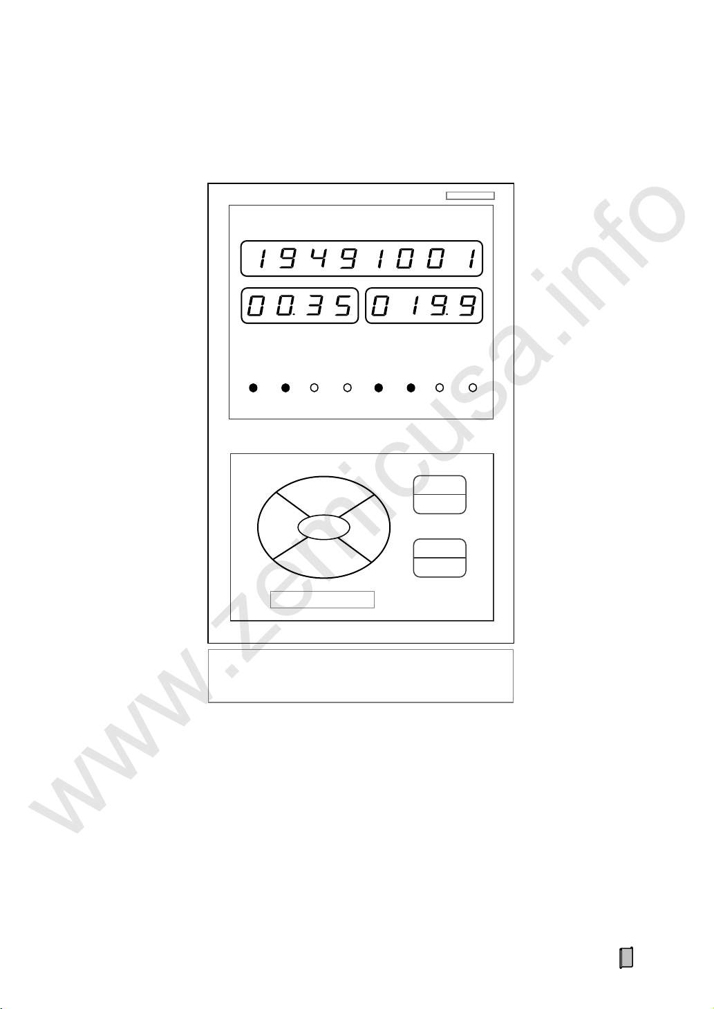
Display Panel A: kg, t, t/h, kg/m
Display Panel B: g, kg, kg/h, g/m
www.zemicusa.info
3.1 Model Panel-mounting Operation Interface
8
3.2 Model Wall-mounting Operation Interface
MENU
ESC
PRINT
ENT
▲
◄
►
▼
RUN
AUTO
EXT
ALARM
kg t t/h
kg/m
Display Panel A: kg, t, t/h, kg/m
Display Panel B: g, kg, kg/h, g/m
www.zemicusa.info
9

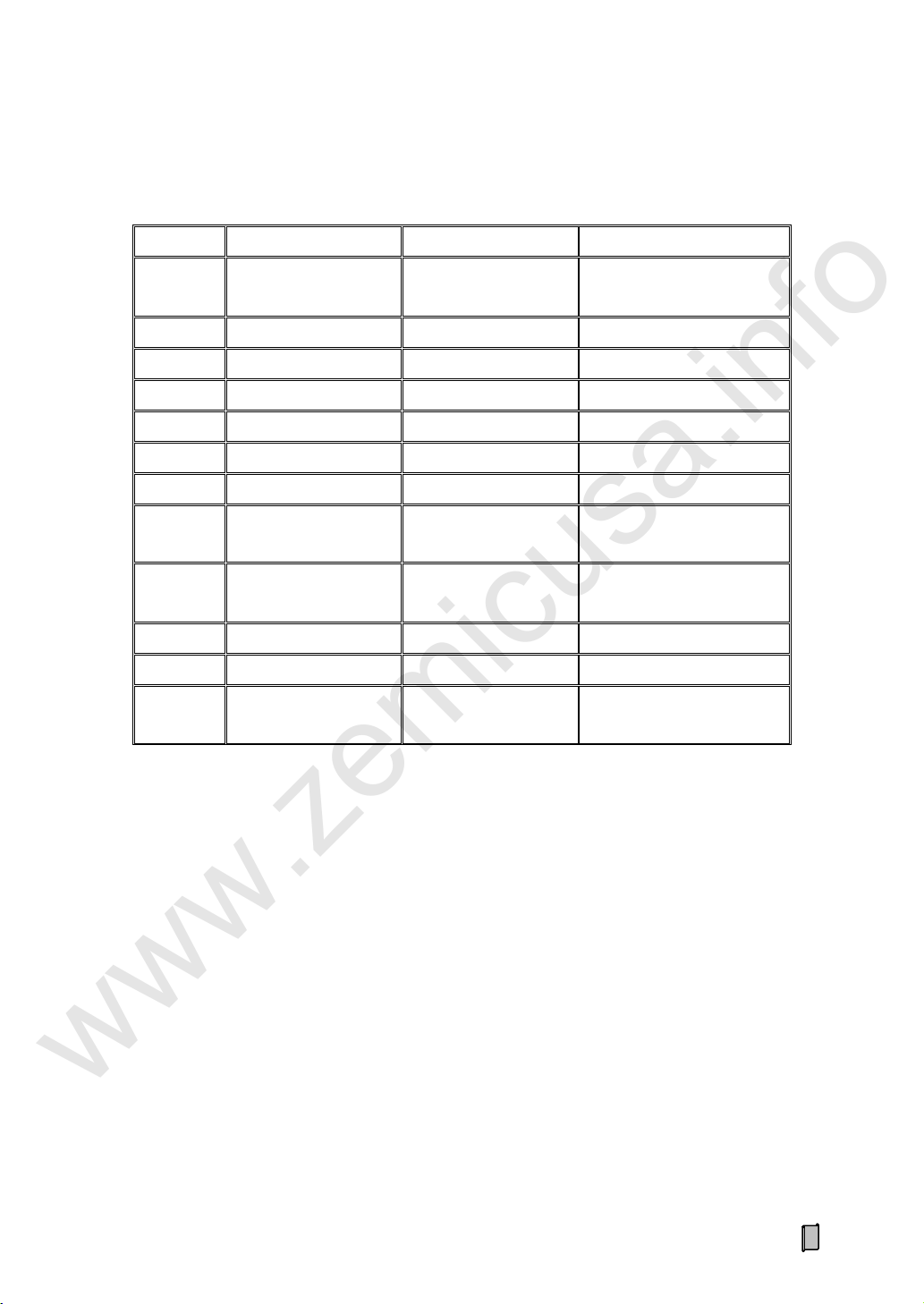
3.3 State Indication
LED Lamp
Description
Note
[RUN]
ON: Weighing state.
OFF: Stopping state.
[AUTO]
Feeding control mode:
ON: Auto [PID].
OFF: Manual.
[EXT]
Flow Set Mode:
ON: External [AI: 4~20mA].
OFF: Internal.
[ALARM]
Alarm. [kg]
Weight Display Unit: kg.
Display Panel A
([P107] Internal Scale Unit=kg)
[t]
Weight Display Unit: t.
[t/h]
Flow Display Unit
ON: t/h.
OFF: kg/min or kg/h.
[kg/m]
Load Display Unit: kg/m.
[g]
Weight Display Unit: g.
Display Panel B
([P107] Internal Scale Unit=g)
[kg]
Weight Display Unit: kg.
[kg/h]
Flow Display Unit
ON: kg/h.
OFF: g/min or g/h.
[g/m]
Load Display Unit: g/m.
www.zemicusa.info
10

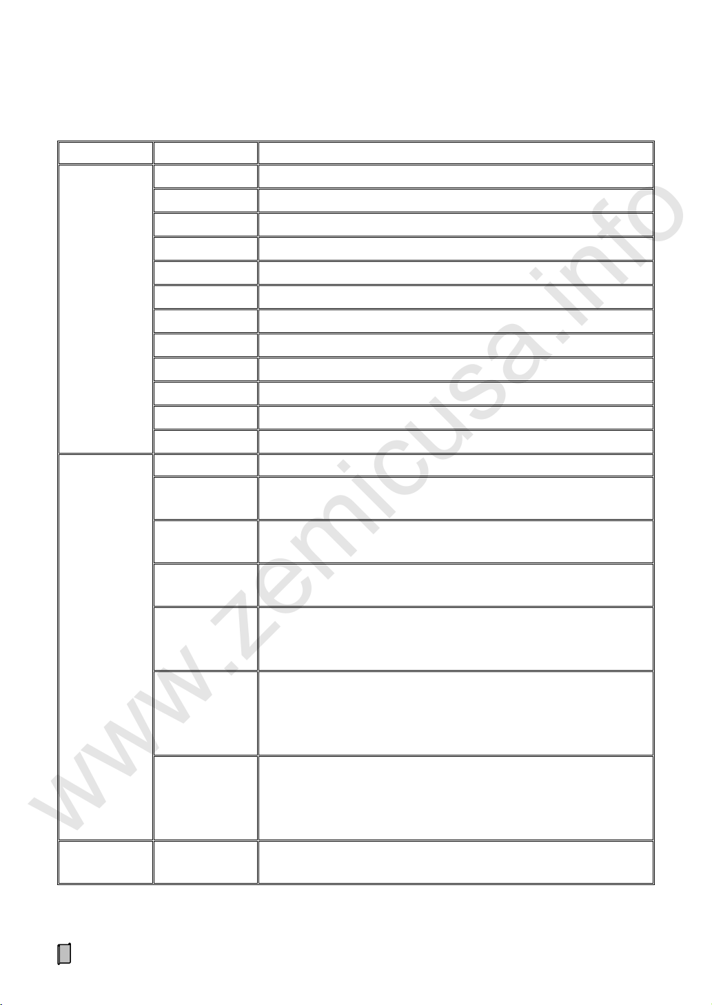
3.4 Keypad Operation
Key Name
Description
【MENU】
【ESC】
Enter Main Menu.
Exit.
【ENT】
Enter/Save.
【◄】
Cursor shifts left.
【►】
Cursor shifts right.
【▲】
Cursor shifts up.
Display the previous interface or option.
Digit input: +1.
【▼】
Cursor shifts down.
Display the next interface or option.
Digit input: -1.
Key Name
Description
【MENU】*
(【LOCK】)
Key-locking.
Key-unlocking.
【◄】
(【ADJ+】)
Control Current +1mA.
【►】
(【ADJ-】)
Control Current -1mA.
【◄】*
(【AUTO】)
„Manual/Auto‟ Control Mode Selection.
【►】*
(【EXT】)
„Internal/External‟ Flow Set Mode Selection.
【PRINT】
Print.
www.zemicusa.info
If there is not any keypad operation in one minute and it‟s not in the processes of „F2 Calibration‟ & „F6 Factory
Adj.‟, the controller will return to „Main Display Interface‟ automatically.
3.4.1 Menu Operation
3.4.2 Quick Operation
*: Keep the key pressed for 2 seconds.
11
4. Installation&Connection
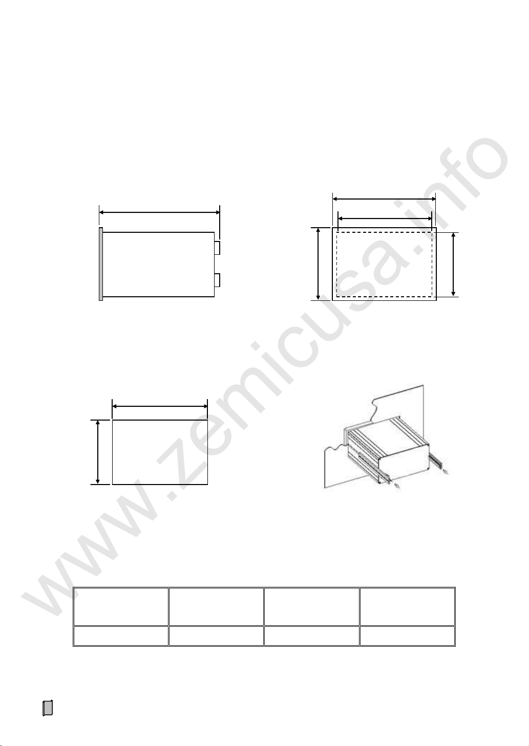
Outline dimension
W×H×D [mm]
Panel dimension
W×H [mm]
Box dimension
W×H [mm]
Cut dimension
W×H [mm]
160×84×188
160×84
150×75
151×76
Installation Mode
151
76
Cut dimension
Outline dimension
Panel dimension
188
84
160
(75)
(150)
www.zemicusa.info
4.1 Installation
4.1.1 Model Panel-mounting Installation
12

4.1.2 Model Wall-mounting Installation
Outline dimension
W×H×D [mm]
Mounting dimension
W×H [mm]
Mounting hole dimension
[mm]
202×305×90
169×271
Ф9
Outline dimension
Installation mode
www.zemicusa.info
13

4.2 Terminal
L
N
POWER
SENSOR
SIG-
SIG+
EXC-
EXC+
SHD
VS-
SIN
VS+
SEN+
SEN-
B- (TXD-)
A+(TXD+)
DP-(RXD+)
(RXD-)
DP+
GND
RXD
TXD
+5V
COM2
COM1
LOADCELL
SPEED
AO/AI/PO
AO1+
AO1-
AO2+
AO2-
AO3+
AO3-
AI+
AI-
VIN
PO
DO/DI
DO1+
DO1-
DO2+
DO2-
DO3+
DO3-
DO4+
DO4-
COM
DI1
DI2
DI3
DC12-24V OR AC220V
DC-
DC+
COM
E
AO/AI/PO
DO/DI
AO1+
AO1-
AO2+
AO2-
AO3+
AO3-
AI+
AI-
VIN
PO
DO1+
DO1-
DO2+
DO2-
DO3+
DO3-
DO4+
DO4-
COM
DI1
DI2
DI3
SENSOR
SIG-
SIG+
EXC-
EXC+
SHD
VS-
SIN
VS+
SEN+
SEN-
POWER
N L E
COM1/2
ETHERNET
www.zemicusa.info
4.2.1 Model Panel-mounting Terminal
4.2.2 Model Wall-mounting Terminal
14

4.3 Connection
No.
Pin
Description
1
SEN+
Voltage Feedback + from Loadcell.
[4-wire connection: short to „EXC+‟]
2
SEN-
Voltage Feedback - from Loadcell.
[4-wire connection: short to „EXC-‟]
3
SIG-
Weighing Signal (mV) Input -.
4
SIG+
Weighing Signal (mV) Input +.
5
EXC-
Excitation Voltage Output - for Loadcell.
6
EXC+
Excitation Voltage Output + for Loadcell (DC10V).
7
SHD
Shield. 8 VS-
Voltage Output - for Speed Sensor.
9
SIN
Pulse Signal Input from Speed Sensor.
10
VS+
Voltage Output + for Speed Sensor (DC12V).
SIG+
EXC+
EXC-
SIG-
SIG+
SIG-
SHD
EXC+
EXC-
SEN-
SEN+
SEN+
SEN-
Controller
Loadcell
www.zemicusa.info
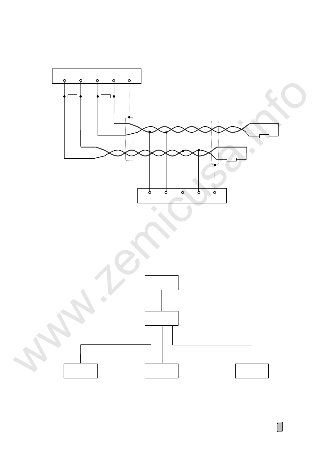
4.3.1 Loadcell & Speed Sensor Connector (SENSOR)
The shielded cable must be used and kept separate from the AC cable and other noise generating
cables. Please use loadcells with the same capacity, bridge resistance & sensitivity (mV/V) for parallel
connection.
4.3.1.1 Loadcell Connection (SENSOR/LOADCELL)
15

4.3.1.2 Speed Sensor Connection (SENSOR/SPEED)
VS-
V-
Controller
SIN
VCC
+5~12V
VS+
SIG
V+
SHD
Proximity Switch
2-wire: VS+ will not be connected.
VS-
V-
Controller
SIN
VCC
+5~12V
VS+
SIG
V+
SHD
Photoelectric Encoder
www.zemicusa.info
4.3.1.2.1 Photoelectric Encoder Connection
4.3.1.2.2 Proximity Switch Connection
16

4.3.1.2.3 Speed Generator Connection
No.
Pin
Description
1
AO1+
4~20mA Analog Signal No.1 Output +/-.
2
AO1-
3
AO2+
4~20mA Analog Signal No.2 Output +/-.
4
AO2-
5
AO3+
4~20mA Analog Signal No.3 Output +/- [Optional].
6
AO3-
7
AI+
4~20mA Input +.
8
AI-
4~20mA Input -.
9
VIN
+5~24V Input for PO.
10
PO
Totalized Weight High-speed Pulse Output.
VS-
Controller
SIN
VCC
+5~12V
VS+
SIG
V+
SHD
Speed Generator
www.zemicusa.info
4.3.2 4~20mA Analog Output/Input & Totalized Weight Pulse Connector (AO/AI/PO)
Max.3 definable AOs (4~20mA) are used for outputting „Flow/Control Current /…‟ signals to external
devices. 1 Optional AI (4~20mA) is used for receiving „Flow Setpoint‟ signal from external devices. 1
High-speed Pulse [PO] is used for outputting Totalized Weight signal to external devices.
17

4.3.2.1 4~20mA Analog Output Connection (AO)
Controller
IN+
AOx+
AOx-
Isolator
Load
Max.500Ω
IN-
OUT+
OUT-
mA+
mA-
Controller
VIN
VCC
PO
Receiver
+5~24VDC
Pulse Input
Weight Per Pulse and Pulse Width can be set.
Controller
OUT+
AI+
AI-
Isolator
Host
OUT-
IN+
IN-
mA+
mA-
www.zemicusa.info
4.3.2.2 4~20mA Analog Input Connection (AI)
4.3.2.3 Totalization Weight Pulse Output Connection (PO)
18

4.3.3 Switch Output/Input Connector (DO/DI)
No.
Pin
Description
1
DO1+
Realy or Transistor Switch No.1 Output +/-.
2
DO1-
3
DO2+
Realy or Transistor Switch No.2 Output +/-.
4
DO2-
5
DO3+
Realy or Transistor Switch No.3 Output +/-.
6
DO3-
7
DO4+
Realy or Transistor Switch No.4 Output +/-.
8
DO4-
9
COM
DI Common Terminal [GND].
10
DI1
Switch Input No.1.
11
DI2
Switch Input No.2.
12
DI3
Switch Input No.3.
www.zemicusa.info
4 Definable normally open relay (AC250V/DC24V, 1A) or transistor (DC24V, 500mA) switches are
used for outputting alarm/control signals to external devices. 3 Definable normally open switch inputs are
used for receiving control signals from external devices.
19
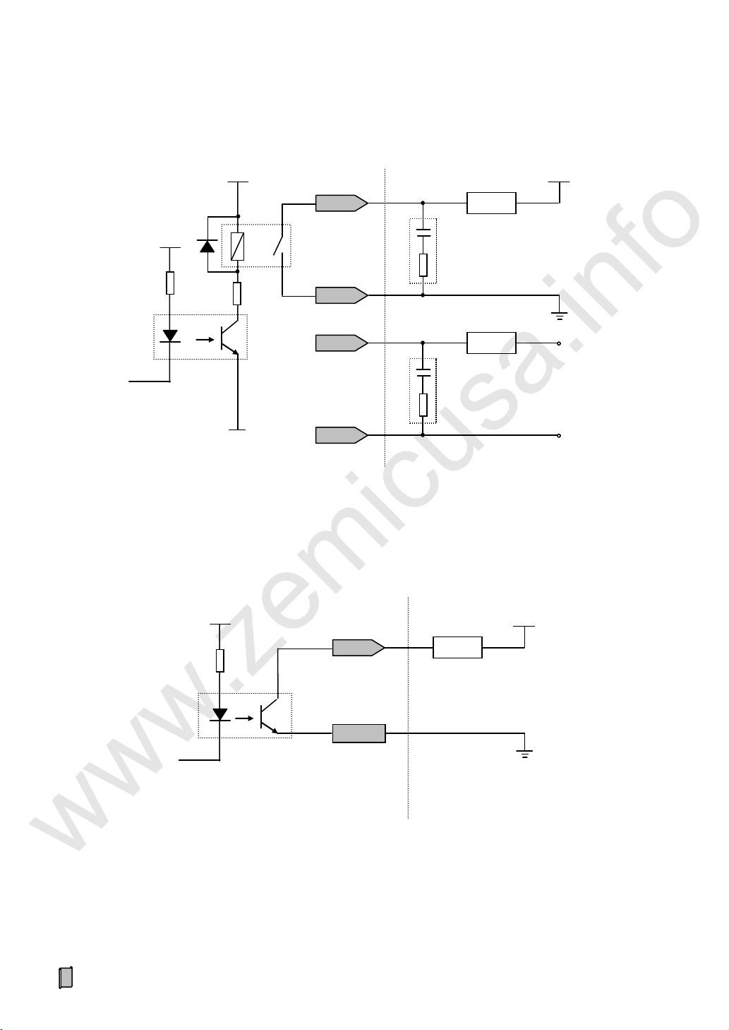
4.3.3.1 Relay Switch Output (DO) to Load Connection
DOx+
DOx-
Controller
Load Circuit
Load
Spark Killer
Load
Spark Killer
AC220V
L
N
DOx+
DOx-
VCC
+5V
+24V
DOx+
VCC
Controller
Load Circuit
Load
DIx
DOx-
+24V
www.zemicusa.info
4.3.3.2 Transistor Switch Output (DO) to Load Connection
20

4.3.3.3 Relay Switch Output (DO) to PLC Connection
PLC
Switch input with common source
IN1
IN2
V+
+24V
DOx+
DOx-
Controller
Controller
IN1
PLC
Switch input with common ground
IN2
COM
+24V
DOx+
DOx-
www.zemicusa.info
21
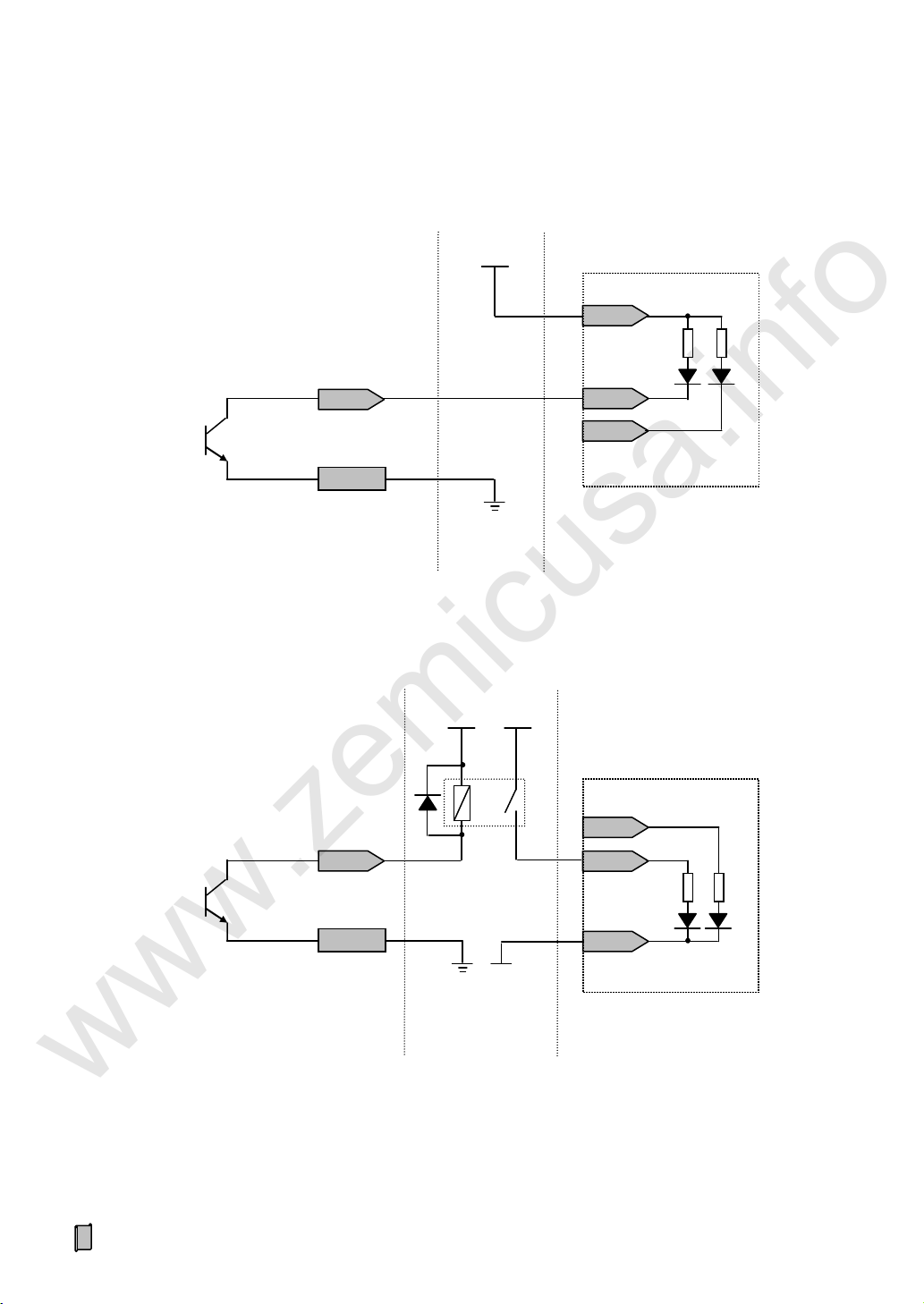
4.3.3.4 Transistor Switch Output (DO) to PLC Connection
Controller
DOx+
IN1
PLC
Switch input with common ground
IN2
DOx-
COM
+24V
Auxiliary Relay
+24V
PLC
Switch input with common source
IN1
IN2
V+
+24V
DOx+
DOx-
Controller
www.zemicusa.info
22

4.3.3.5 Switch Input (DI) to Switch/PLC Connection
DIx
PLC
Switch output with common source
OUT1
V+
Auxiliary Relay
COM
+24V
Controller
VCC
+5V
Controller
VCC
+5V
PLC
Switch output with common ground
OUT1
COM
DIx
OUT1.1
OUT1.2
Switch or
PLC with relay switch output
DIx
COM
COM
www.zemicusa.info
23

4.3.4 Digital Communication Port Connection (COM1/2)
No.
COM1
COM2
RS232
RS485
CANBUS
Profibus-DP
RS422
Ethernet
RS232
1 B- TXD-
2 RXD
A+ TXD+
3 TXD
DP- (B)
RXD+
4
RXD-
5
GND
GND
GND
GND
GND 6 TXD
7
RXD 8 DP+ (A)
9
+5V (+5V/100mA power supply can be used for external wireless
communication device)
No.
COM1
COM2
RS232
RS485
CANBUS
Profibus-DP
RS422
Ethernet
RS232
1 B- TXD-
2 RXD
A+
TXD+
3
TXD
DP- (B)
RXD+
4
RXD-
5 DP+ (A)
6
GND
GND
GND
GND
GND
7
RXD 8 TXD
9
+5V (+5V/100mA power supply can be used for external wireless
communication device)
www.zemicusa.info
COM1 Optional: RS232/RS485/RS422/Profibus-DP/CANBUS/Ethernet modules.
COM2: RS232.
Connectable: IPC/PLC, Remote Display&Operation Terminal, Serial Printer and Wireless Module.
4.3.4.1 Model Panel-mounting Communication Port
4.3.4.2 Model Wall-mounting Communication Port
24

4.3.4.3 RS232 to IPC/PLC Host-slave&Point-to-point Network
Host (IPC/PLC)
Slave: Controller
TXD
Max. transmission distance: 15m.
Communication mode: Host-slave.
RXD
GND
TXD
RXD
GND
Controller
Serial Printer/Remote Display&Operation Terminal
TXD
Max. transmission distance: 15m.
Communication mode:
To serial printer: Print.
To remote display terminal: Continuous.
To remote operation terminal: Host-slave.
RXD
GND
TXD
RXD
GND
www.zemicusa.info
4.3.4.4 RS232 to Printer, Remote Display&Operation Terminal Point-to-point Network
25

4.3.4.5 RS485/CANBUS/Profibus-DP to IPC/PLC Host-slave Data-bus Network
B A GND
Host (IPC/PLC)
Slave: Controller
…
1#
…
R
B
A
GND
N#
B
A
GND
R
Terminal resistor R=120~150Ω.
RS485 max. transmission distance: 1200m.
Communication mode:
RS485/CANBUS: Host-slave.
Profibus-DP: DP-Modicon/DP-Siemens.
N≤31
B A GND
Controller
Remote Display&Operation Terminal
R
B A GND
R
Terminal resistor R=120~150Ω.
Max. transmission distance: 1200m.
Communication mode:
To remote display terminal: Continuous.
To remote operation terminal: Host-slave.
www.zemicusa.info
4.3.4.6 RS485 to Remote Display&Operation Terminal Point-to-point Network
26
4.3.4.7 RS422 to IPC/PLC Host-slave Data-bus Network
Host (IPC/PLC)
Slave: Controller #1~N, N≤31
R
Terminal resistor R=120~150Ω.
Max. transmission distance: 1200m.
Communication mode: Host-slave.
RXD+
RXD-
GND
TXD-
TXD+
R
RXD+
RXD-
GND
TXD-
TXD+
R
R
Host
Slave #1 (IP1)
IPC/PLC
Controller
Switch
10/100Mbps Fast Ethernet Switch
Controller
Controller
Slave #2 (IP2)
Slave #N (IPn)
…
Ethernet
Ethernet
Communication mode: Host-slave.
www.zemicusa.info
4.3.4.8 Ethernet Host-slave Network
27

4.3.5 Power Supply Connector (POWER)
Pin
Description
Voltage
N
Null Wire.
AC220V±15%.
E
Earth Wire.
L
Live Wire.
Pin
Description
Voltage
DC-
DC Input -.
DC24V±20%.
DC+
DC Input +.
Optional for Model Wall-mounting.
www.zemicusa.info
Please make sure that the power supply is correct before power-on. If the voltage fluctuation exceeds
the allowable range, please use regulated power supply.
4.3.6 Ground Protection
For avoiding electric shocks, the metal shell should be grounded directly.
28
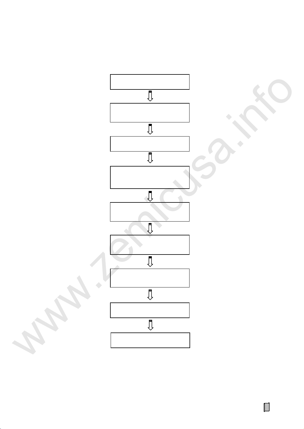
5. Operation Procedure
Connection & Power on
Zero Calibration
I/O Setting
Serial Port Setting
Control Setting
(Used for belt feeder)
Other Settings
„Weighing Dead Band‟ Setting
(Scale Setting)
Key-Locking
„Speed Coeff.‟ & „Belt Length‟
Setting (Scale Setting)
Dynamic Span Calibration
Or Static Span Calibration
www.zemicusa.info
29

6. Function&Operation
RUN
AUTO
EXT
ALARM
kg t t/h
kg/m
RUN
RUN
EXT
ALARM
kg t t/h
kg/m
RUN
AUTO
EXT
ALARM
kg t t/h
kg/m
【ENT】: Set „Flow Setpoint‟ value
www.zemicusa.info
The following display&operation interfaces are described with „kg‟ as the Internal Scale Unit. If the
parameter „[P107] Internal Scale Unit‟ is set to „g‟, the actual Weight Display Unit will be different.
6.1 Main Display Interface
【▲】【 ▼】: Display the next/previous interface.
6.1.1 Totalized Weight, Belt Speed & Flow
Press【PRINT】key to print: 2009-05-20 23:59
19491001kg
6.1.2 Totalized Weight, Flow Setpoint & Flow
30
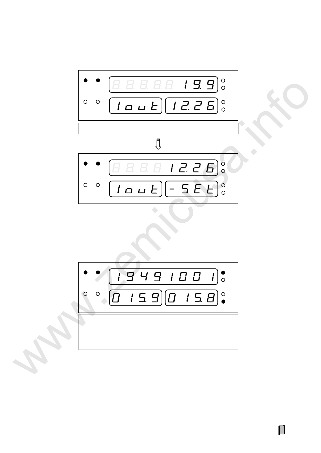
6.1.3 Flow & Control Current
【◄】【 ►】: Control Current Iout ±1mA
RUN
AUTO
EXT
ALARM
kg
t
t/h
kg/m
RUN
AUTO
EXT
ALARM
kg t t/h
kg/m
【ENT】: Set „Control Current‟ value
RUN
AUTO
EXT
ALARM
kg t t/h
kg/m
Load=Flow / (3.6×Speed)
Load Setpoint=Flow Setpoint / (3.6×Speed)
Load: kg/m; Flow: t/h
Belt Speed: m/s
www.zemicusa.info
6.1.4 Totalized Weight, Load Setpoint & Load
31
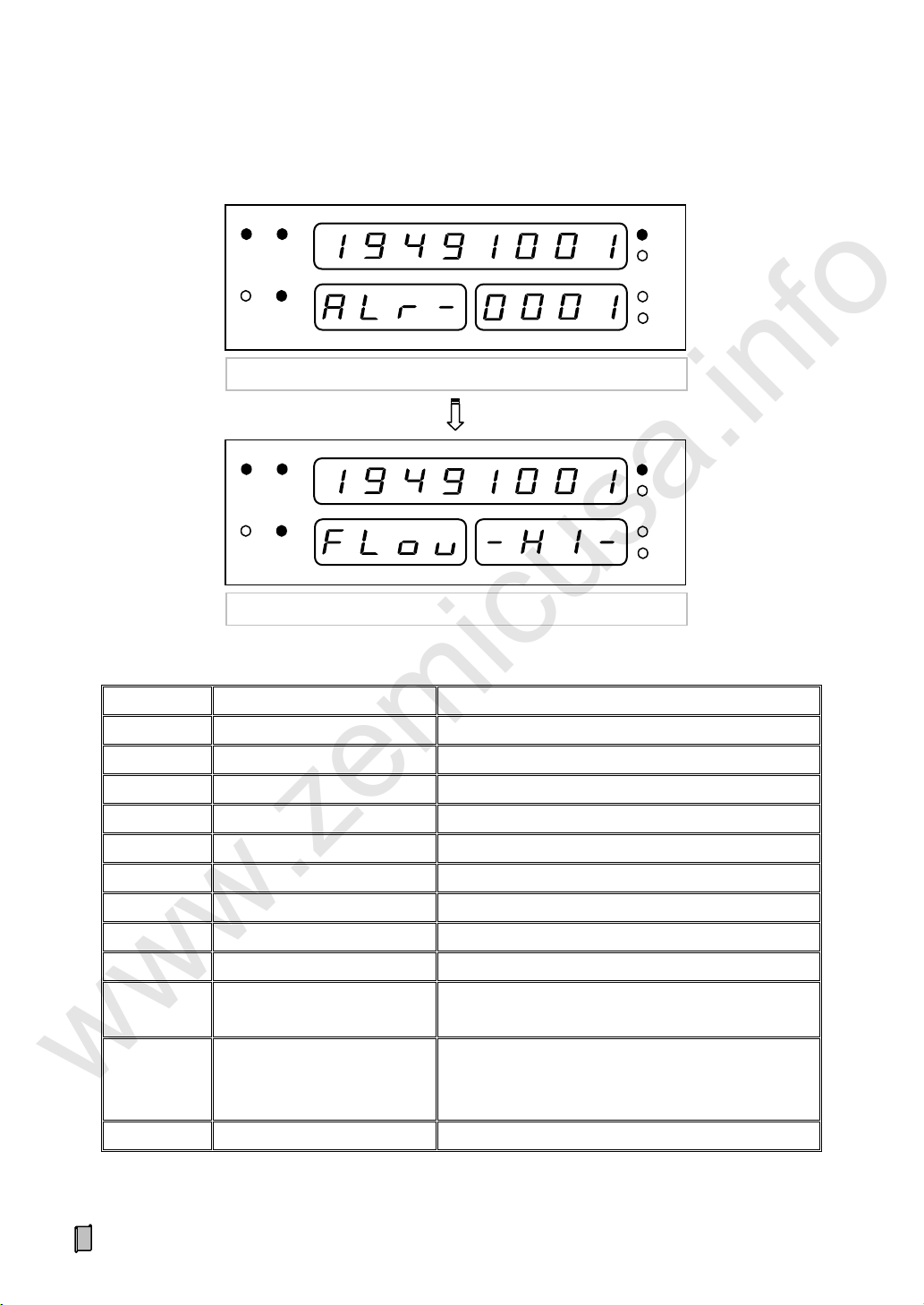
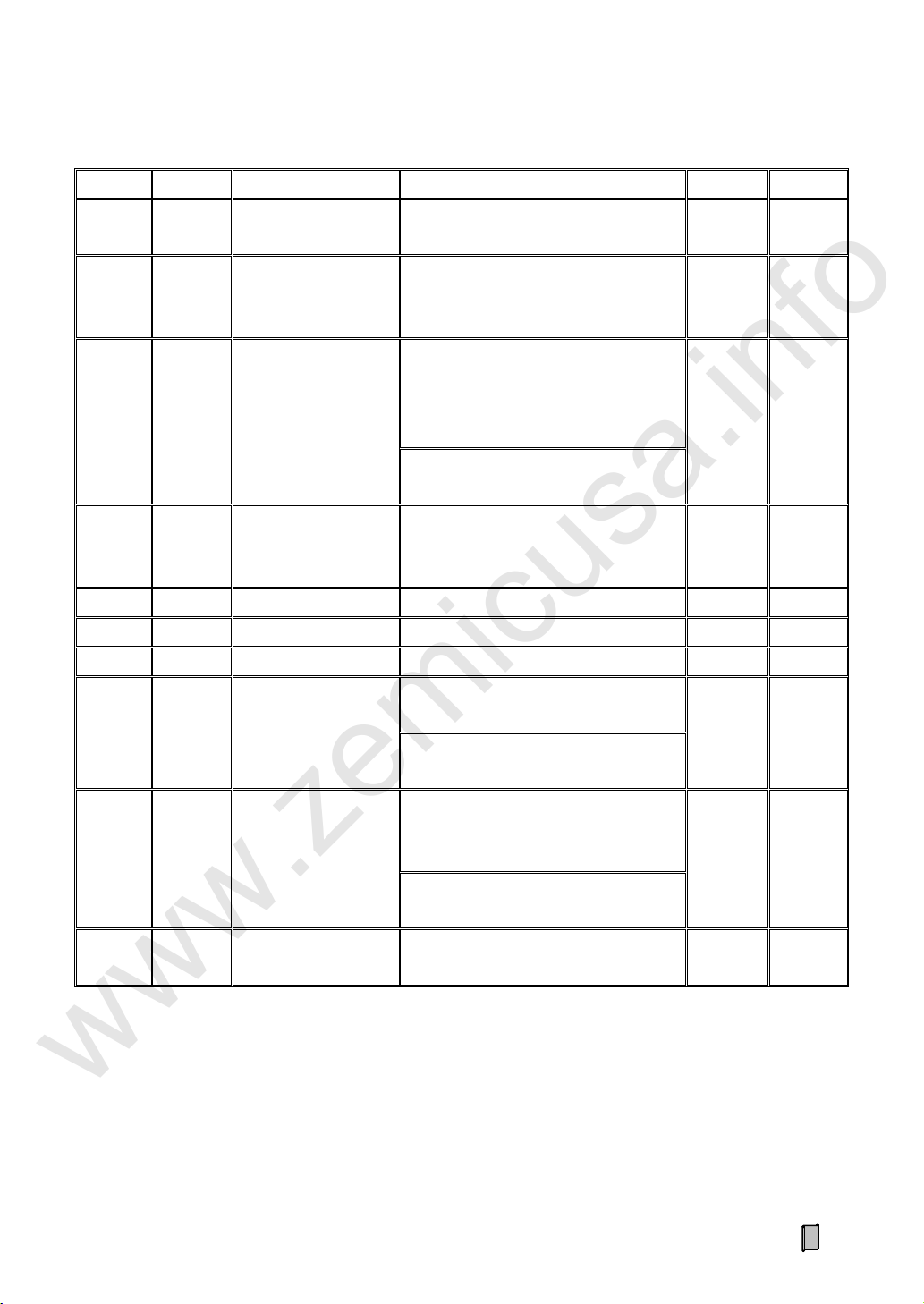
6.1.5 Alarm Items
Sign
Alarm Item
Alarm Condition
FLou -HI-
Flow Upper Limit
Flow ≥ Flow Range × Flow Upper Limit(%)
FLou -Lo-
Flow Lower Limit
Flow ≤ Flow Range × Flow Lower Limit(%)
LoAd -HI-
Load Upper Limit
Load ≥ Load Range × Load Upper Limit(%)
LoAd -Lo-
Load Lower Limit
Load ≤ Load Range × Load Lower Limit(%)
SPEd -HI-
Speed Upper Limit
Speed ≥ Speed Range × Speed Upper Limit(%)
SPEd -Lo-
Speed Lower Limit
Speed ≤ Speed Range × Speed Lower Limit(%)
PId- -HI-
Control Current Upper Limit
Control Current ≥ PID Control Current Upper Limit
PId- -Lo-
Control Current Lower Limit
Control Current ≤ PID Control Current Lower Limit
dEV- -HI-
Flow Positive Deviation Limit
Flow Deviation [E%] > Flow Positive Deviation Limit
dEV- -Lo-
Flow Negative Deviation Limit
Flow Deviation [E%] < (-Flow Negative Deviation
Limit)
dEV=XXX.X
Flow Deviation Value [E%]
0.0~999.9%
Flow Deviation [E%] = ((Flow - Flow Setpoint) /
Flow Setpoint) × 100%
XXXX ----
Normal
RUN
AUTO
EXT
ALARM
kg t t/h
kg/m
RUN
AUTO
EXT
ALARM
kg t t/h
kg/m
【ENT】: Alarm Query
【▲】【 ▼】: Query Switch; 【MENU】: Exit
ALr- Alarm Count
www.zemicusa.info
32
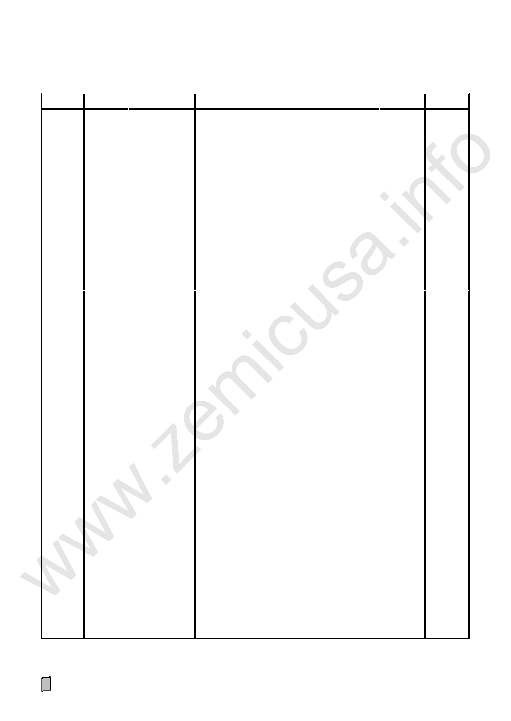
6.1.6 Other Display Interface
NO.
Display iterms
Sign
Range
6
Totalized Weight of
Current Batch
P=
0~999999
7
AD Value
Ad=
0~65535
8
Zero Value
Zr=
0~60000
9~11
DI State
dI1-/dI2-/dI3-
-oFF/-on-
12~15
DO State
do1-/do2-/do3-/do4-
-oFF/-on-
16
AI Signal
AI1=
4.00~20.00mA
17~19
AO Signal
Ao1=/Ao2=/Ao3=
4.00~20.00mA
20
Totalized Weight High
Speed Pulse
HP
0~999999 Pulse
21
Totalized Weight Low
Speed Pulse
LP
0~999999 Pulse
22
Date
20YY.MM.DD
Year. Month. Day
23
Time
HH.MM.SS-W
Hour. Minute. Second-Week
24
Totalized Weight of
Current Shift
t=
0~99999.9t
www.zemicusa.info
The Numeric Display 1 displays Totalized Weight value and the Numeric Display 2-3 displays the following data:
33
6.2 Main MENU
Main Menu
Second Menu
Description
≡F1-SEt≡
Setting
--SCAL--
Basic scale parameters setting.
--SCAL1-
Extra scale parameters setting.
--CtrL--
Basic feeding control parameters setting.
--CtrL1-
Extra feeding and batching control parameters setting.
--Flou--
Flow parameters setting.
--SPEd-
Speed parameters setting.
--LoAd--
Load parameters setting.
--SAVE--
Weight record parameters setting.
--SErP--
Communication parameters setting.
---Io---
Input/output parameters setting.
--dISP--
Display and operation interface parameters setting.
--tIEE--
Date/Time parameters setting.
≡F2-CAL≡
Calibration
--ZEro--
Zero Calibration without loading for correcting Zero Value.
--LoAd--
Dynamic Span Calibration with loading materials or Poise Weights for
correcting Span Coefficient.
-CHAn--
Static Span Calibration with a measured chain weight as a continuous and
steady load on the running belt weigher for correcting Span Coefficient.
--HAng--
Static Span Calibration with a measured Hanging Weight as a steady load
on the running belt weigher for correcting Span Coefficient.
--SEgC--
Segmenting Span Correction. After doing Dynamic or Static Span
Calibration, further corrections for 3 [AD Value: 0~60000] linear segments
are optional for correcting Correction Coefficient 1~3.
--SPEd--
Speed Coefficient Calibration.
Keep the belt weigher running at a constant speed. After the running time of
a revolution being measured with using a stopwatch, do this operation for
correcting Speed Coefficient.
--LEnS--
Belt Length Calibration.
Keep the belt weigher running at a constant speed. After the running time of
a revolution being measured with using a stopwatch, do this operation for
correcting Belt Length.
≡F3-rEC≡
Weight Record
Query and print Weight Records.
www.zemicusa.info
34

Main Menu
Second Menu
Description
≡F4-CLS≡
Data Clearing
---CLS--
Clear Screen: Clear Totalized Weight and Totalized Weight Pulse Count.
But Totalized Weight of Current Shift will not be cleared, so this operation
has no effect on recording of weight per shift.
---CLt--
Clear Weight: Clear Totalized Weight, Totalized Weight Pulse Count and
Totalized Weight of Current Shift.
The cleared value of Totalized Weight of Current Shift will not be recorded.
---CLr--
Clear Records: Clear History Records of Totalized Weight.
But Current Totalized Weight, Totalized Weight Pulse Count and Totalized
Weight of Current Shift will not be cleared.
≡F5-SAF≡
Security
--ALoc--
Auto-locking: If there is not any keypad operation in one minute and it‟s not
in the processes of „F2 Calibration‟ & „F6 Factory Adj.‟, the controller will
lock the keypad and return to „Main Display Interface‟ automatically.
--Locc--
Locking keypad.
--oPEn--
Unlocking keypad.
--PASS--
Set Password.
Exfactory Password: 001.
--dEFU--
RAM Reset: Restore to factory defaults.
≡F6-FAC≡
Factory Adj.
--Ao1E--
AO1 Zero Adjustment.
--Ao1F--
AO1 Full Range Adjustment.
--Ao2E--
AO2 Zero Adjustment.
--Ao2F--
AO2 Full Range Adjustment.
--Ao3E--
AO3 Zero Adjustment.
--Ao3F--
AO3 Full Range Adjustment.
--AI1E--
AI Zero Adjustment.
--AI1F--
AI Full Range Adjustment.
≡F7-InF≡
Product Info.
---VEr--
Version No.: Only for query.
---Sn---
Serial No.: Only for query.
--dAtE--
Exfactory Date: Only for query.
--AudIt-
Audit Counter: Audit Trail Counter [0~99999999] for Scale parameter‟s
modification. Only for query.
--AutH--
Authorization Code: Only for query.
www.zemicusa.info
35

6.3 F1-SET Setting
No.
Sign
Parameter
Range
Default
Set
P100
UnIt
Weight Display Unit
0: kg
1: t
([P107] Scale Unit = kg)
0
0: g
1: kg
([P107] Scale Unit = g)
P101
-dot
Weight Decimal Point
0: o
1: o.o
2: o.oo
When [P100]=1, it‟s valid.
1
P102
--L-
Belt Length
0.01~5000.00m
10.00[*]
P103
--C-
Speed Coefficient
1.0~99999.9 pulse/m
100.0[*]
P104
ZEro
Zero Value
0~60000 (Max. AD Value)
15000[*]
P105
CALC
Span Coefficient
1~99999999
200000
[*]
P106
dEAd
Weighing Deadband
±(0.00~200.00) t/h
([P107] Scale Unit = kg)
If Flow < Deadband value, the variance of
Totalized Weight will be ignored.
±0.00
±(0.00~200.00) kg/h
([P107] Scale Unit = g)
P107
SCAL
Internal Scale Unit
0: kg
1: g
0/1[*]
www.zemicusa.info
6.3.1 Basic Scale Parameters (SCAL)
* „RAM Reset‟ operation has no effect on this parameter.
36

6.3.2 Extra Scale Parameters (SCAL1)
No.
Sign
Parameter
Range
Default
Set
P110
-Cn-
Calibration Revolutions
1~99R (1R=1 Belt Length)
3
P111
CHAn
Chain Weight
0.1~1000.0kg/m
([P107] Scale Unit = kg)
Chain Weight for Span Calibration
10.0
0.1~1000.0g/m
([P107] Scale Unit = g)
P112
HAng
Hanging Weight
0.1~1000.0kg
([P107] Scale Unit = kg)
Hanging Weight for Span Calibration
10.0
0.1~1000.0g
([P107] Scale Unit = g)
P113
SCLL
Weigh Length
0.001~50.000m
1.000
P114
CALI
Calibration Current
4.00~20.00mA
Control Current for System Calibration
12.00
P115
-Zt-
Zero Tracking
Permission
0: OFF; 1: ON
0
P116
-tr-
Zero Tracking Range
±(0~10%) × [P302] Flow Range
±5%
P117
-ZA-
Zero Adjusting Range
±(0~10%) × [P104] Zero Value
±5%
P118
-Zr-
Zero Refresh
0: RAM (Only Refresh RAM Zero Value)
1: FLASH/RAM (Refresh Original Zero
Value)
0
P119
-SP1
Breakpoint1
0~[P120] (AD Value: 0~60000)
Breakpoint1 of Segmenting Span
Correction
18000
P120
-SP2
Breakpoint2
[P119]~Max. AD Value (60000)
Breakpoint2 of Segmenting Span
Correction
42000
P121
-C1-
Span Correction
Coefficient 1
0.500~2.000; Span Correction Coefficient
of AD Value Linear Segment 1: 0~[P119]
1.000
P122
-C2-
Span Correction
Coefficient 2
0.500~2.000; Span Correction Coefficient
of AD Value Linear Segment 2:
[P119]~[P120]
1.000
P123
-C3-
Span Correction
Coefficient 3
0.500~2.000; Span Correction Coefficient
of AD Value Linear Segment 3:
[P120~Max. AD Value
1.000
P124
CAdd
Totalizing While
Calibrating
0: OFF
1: ON [In the process of „Load
Calibration‟, the inputted actual weight
value will be added to Totalized Weight]
0
P125
nAdd
Negative Totalizing
0: OFF [The negative variance
of Totalized Weight will be ignored]
1: ON
1
www.zemicusa.info
37

6.3.3 Basic Control Parameters (CtrL)
No.
Sign
Parameter
Range
Default
Set
P200
SEtF
Flow Setpoint
0.00~5000.00t/h
([P107] Scale Unit = kg)
20.00
0.00~5000.00kg/h
([P107] Scale Unit = g)
P201
--P-
P Value
0.1~5000.0
A bigger P value indicates a higher-precision
feeding adjustment but a longer time for flow
to reach the target value [Flow Setpoint].
100.0
P202
--I-
I Value
0.1-9.9s
A smaller I value indicates a higher-frequency
feeding adjustment but a potential flow
over-adjustment.
0.5
P203
PIHI
PID Upper Limit
[P204]~20.00mA
Auto[PID]/Manual Control Current Upper
Limit
20.00
P204
PILo
PID Lower Limit
4.00~[P203]mA
Auto[PID]/Manual Control Current Lower
Limit
5.00
P205
rAtE
PID Control Ratio
1~500%
The 2nd&3rd Control Current=Control
Ratio×(The 1st Control Current-4.00)+4.00
[mA]
100%
P206
oVEr
Flow Positive
Deviation Limit
(0.5~100.0)%
10.0%
P207
Undr
Flow Negative
Deviation Limit
(0.5~100.0)%
10.0%
P208
CtrL
Feeding Control
Mode
0: Auto[PID]
1: Manual
2: Communication
1
P209
FLSt
Flow Set Mode
0: Internal/Communication
1: External AI: 4~20mA
0
www.zemicusa.info
38
6.3.4 Extra Control Parameters (CtrL1)
No.
Sign
Parameter
Range
Default
Set
P210
PIdL
PID Initial Current
Hold Time
0.0-999.9s
2.0
P211
InIC
PID Initial Current
0: Present (Present Current Value)
1: Fuzzy (Fuzzy Current Value)
2: Set [P219] (Set Value of [P219])
0
P212
FuZE
Fuzzy Equivalent
0.01~100.00 [t/h]/mA
([P107] Scale Unit = kg)
Flow Increment per Increasing 1mA
Adjusting Current.
2.50
0.01~100.00 [kg/h]/mA
([P107] Scale Unit = g)
P213
StdL
Start/Stop Delay
0.0~999.9s
Delay Time of Feeder Starting
Delay Time of Scale Stopping
0.0
P214
bCon
Batch Permission
0: OFF; 1: ON
0 P215
-bSt
Batch Loop Mode
0: Manual Mode; 1: Auto Mode
0 P216
-bdL
Batch Interval
0.0-9999.9s
60.0
P217
SEtb
Batch Weight Setpoint
0~99999999kg
([P107] Scale Unit = kg)
0
0~99999999g
([P107] Scale Unit = g)
P218
SEtP
Batch Preact Weight
0~[P217] kg
([P107] Scale Unit = kg)
Batch Preact Weight
0
0~[P217] g
([P107] Scale Unit = g)
P219
SEtI
Set Value of PID
Initial Current
4.00~20.00mA
12.00
www.zemicusa.info
Note:
[P213] Start/Stop Delay:
1. Delay Time of Feeder Starting: When there is a “DI.Start” pulse signal input, „DO. Scale Start&Stop Control‟ will
turn on to start the belt weigher, and after delaying this time, „DO. Feeder Start&Stop Control‟ will turn on to start the
feeder.
2. Delay Time of Scale Stopping: When there is a “DI.Stop” pulse signal input, „DO. Feeder Start&Stop Control‟ will
turn off to stop the feeder, and after delaying this time, „DO. Scale Start&Stop Control‟ will turn off to stop the belt
weigher.
39

6.3.5 Flow Parameters (Flou)
No.
Sign
Parameter
Range
Default
Set
P300
UnIt
Flow Display Unit
0: t/h
1: kg/min
2: kg/h
([P107] Scale Unit = kg)
0
0: kg/h
1: g/min
2: g/h
([P107] Scale Unit = g)
P301
-dot
Flow Decimal Point
0: o; 1: o.o; 2: o.oo
1
P302
rAng
Flow Range
0.01~5000.00t/h
([P107] Scale Unit = kg)
100.00
0.01~5000.00kg/h
([P107] Scale Unit = g)
P303
-HI-
Flow Upper Limit
(0.0~100.0)% Flow Range
100.0%
P304
-Lo-
Flow Lower Limit
(0.0~100.0)% Flow Range
0.0%
P305
FILt
Flow Filter
1~200
10
P306
FLt2
Flow Filter 2
1~100
The secondary filter for flow display.
1
P307
FdEV
Flow Deviation Range
for Filter2
±(0~20)%
When Flow Deviation [E%] is within
this range, the secondary filter will
work.
±2%
www.zemicusa.info
40

6.3.6 Speed Parameters (SPEd)
No.
Sign
Parameter
Range
Default
Set
P400
-dot
Speed Decimal Point
0: o
1: o.o
2: o.oo
3: o.ooo
2
P401
rAng
Speed Range
0.100~5.000m/s
3.000
P402
-HI-
Speed Upper Limit
(0.0~100.0)% Speed Range
100.0%
P403
-Lo-
Speed Lower Limit
(0.0~100.0)% Speed Range
0.0%
P404
FILt
Speed Filter
1~200
10
P405
PuLS
Speed Source
0: Ext. Speed (Weighing by the external
speed)
1: Int. Speed1 (Weighing by the internal
speed)
2: Int. Speed2 (Connect a normally open
switch related to the running state of the
weighing belt between the terminals „SIN‟
and „VS-‟. Switch ON with Belt‟s
Running: Weighing by the internal speed;
Switch OFF with Belt‟s Stopping: Stop
weighing)
3: Int. Speed3 (Weighing by the internal
speed while the external speed pulse
inputting)
Note: If a DI signal is defined as „1:
Weighing‟, then only when this DI turns
on, the weighing process is allowed.
0
P406
InPL
Internal Speed
0.001~5.000m/s
0.500
P407
FrEH
Speed Pulse Frequency
Upper Limit
0.1~3.0kHz
If the frequency of speed pulse exceeds
this set value, the speed pulse will be
invalid.
1.0
www.zemicusa.info
41

6.3.7 Load Parameters (LoAd)
No.
Sign
Parameter
Range
Default
Set
P500
-dot
Load Decimal Point
0: o
1: o.o
2: o.oo
1
P501
rAng
Load Range
0.01~5000.00kg/m
([P107] Scale Unit = kg)
100.00
0.01~5000.00g/m
([P107] Scale Unit = g)
P502
-HI-
Load Upper Limit
(0.0~100.0)% Load Range
100.0%
P503
-Lo-
Load Lower Limit
(0.0~100.0)% Load Range
0.0%
P504
FILt
Load Filter
1~20
10
P505
LdCA
Speed for Calculation
0.000 (Use external speed for Load
calculation)
0.001~5.000m/s (Used for Load
calculation)
0.000
No.
Sign
Parameter
Range
Default
Set
P600
SHFn
Shifts per Day
1: One Shift; 2: Two Shifts;
3: Three Shifts; 4: Four Shifts
3
P601
SHF1
Shift1 Time
00:00~23:59
07:59
P602
SHF2
Shift2 Time
00:00~23:59
15:59
P603
SHF3
Shift3 Time
00:00~23:59
23:59
P604
SHF4
Shift4 Time
00:00~23:59
23:59
P605
APrt
Auto-print
0: OFF; 1: Per Hour
2: Per Shift; 3: Per Day
0
P606
ACLn
Auto Clear Screen
0: OFF; 1: Per Shift
2: Per Day; 3: Per Month
„Auto-clear‟ has no effect on recording of
weight per shift.
0
www.zemicusa.info
6.3.8 Weight Record Parameters (SAVE)
42

6.3.9 Communication Parameters (SErP)
No.
Sign
Parameter
Range
Default
Set
P700
-Adr
Communication Address
00~99
01
P701
P702
bPS1
bPS2
COM1 Baud Rate
COM2 Baud Rate
0: 1200bps
1: 2400bps
2: 4800bps
3: 9600bps
4: 19200bps
5: 115200bps
3
3
P703
P704
CHC1
CHC2
COM1 Parity Check
COM2 Parity Check
0: None
1: Even
2: Odd
0
0
P705
Con1
COM1 Communication
Mode
0: Host-slave Modbus ASCII
1: Continuous Sending ASCII
2: DP-Modicon (Profibus-DP; Data
Format: 4321)
3: DP-Siemens (Profibus-DP; Data
Format: 1234)
4: Print[A]
5: Print[B]
6: Host-slave Modbus RTU
7: Continuous Sending RTU
8: TCP
9: User1
0
P706
Con2
COM2 Communication
Mode
0: Host-slave Modbus ASCII
1: Continuous Sending ASCII
2: Unused
3: Unused
4: Print[A]
5: Print[B]
6: Host-slave Modbus RTU
7: Continuous Sending RTU
8: TCP
9: User1
0
P707
dAtF
Data Format
0: 4321
1: 3412
2: 1234
3: 2143
0
www.zemicusa.info
43
6.3.10 I/O Parameters (-Io-)
No.
Sign
Parameter
Range
Default
Set
P800
P801
P802
-Ao1
-Ao2
-Ao3
AO1 Signal
AO2 Signal
AO3 Signal
0: None
1: Flow
2: Control Current
3: Load
4: Speed
5: From AI [4~20mA]
6: From Communication Port
7: Totalized Weight High-speed Pulse (4mA→
20mA→4mA)
8: Totalized Weight Low-speed Pulse (4mA→
20mA→4mA)
9: Batch Weight (Output Capacity: [P217]
„Batch Weight Setpoint‟)
1
2 0
P803
P804
P805
P806
-do1
-do2
-do3
-do4
DO1 Signal
DO2 Signal
DO3 Signal
DO4 Signal
0: None
1: Flow Upper Limit Alarm
2: Flow Lower Limit Alarm
3: Load Upper Limit Alarm
4: Load Lower Limit Alarm
5: Speed Upper Limit Alarm
6: Speed Lower Limit Alarm
7: PID Upper Limit Alarm
8: PID Lower Limit Alarm
9: Flow Positive Deviation Limit Alarm
10: Flow Negative Deviation Limit Alarm
11: Totalized Weight Low-speed Pulse
12: Auto Feeding Control Mode
13: Calibrating State
14: Running State
15: From DI1
16: From DI2
17: From DI3
18: From Communication Port
19: Feeder Start&Stop Control
20: Belt Weigher Start&Stop Control)
21: BatchEnd[ON] (Totalized Weight reaches to
Batch Weight Setpoint)
22: BatchEnd[OFF] (Totalized Weight reaches
to Batch Weight Setpoint)
0
0
0
0
www.zemicusa.info
44
No.
Sign
Parameter
Range
Default
Set
P807
P808
P809
-dI1
-dI2
-dI3
DI1 Signal
DI2 Signal
DI3 Signal
0: None
1: Weighing (ON: Weighing; OFF: No
Weighing)
2: PID Start (ON: Start PID; OFF: Stop PID)
3: Sys. Ready (ON: System Ready, DI.Start
Signal is valid)
4: Zero Calibration (OFF→ON→OFF)
5: Clear Screen (OFF→ON→OFF)
6: Start (OFF→ON→OFF)
7: Stop (OFF→ON→OFF)
8: Feeding Control Mode (ON: Auto Control;
OFF: Manual Control)
9: Flow Set Mode (ON: Internal; OFF: External)
10: Clear Batch (OFF→ON→OFF, Clear Batch
Weight)
11: Batch Permit (ON: Batch Control)
12: End Batch (OFF→ON→OFF)
0
0 0
P810
ALSo
Alarm Sound
0: OFF
1: ON
0 P811
ALdL
Alarm Delay
0.0~9.9s
Alarm Delay Time
1.0
P812
HIPL
HP Weight
1~1000kg
([P107] Scale Unit = kg)
Weight value per high-speed pulse outputting
from PO/AO port
100
1~1000g
([P107] Scale Unit =kg)
P813
HIPt
HP Width
50~500ms
Width of high-speed pulse
100
P814
LoPL
LP Weight
10~10000kg
([P107] Scale Unit = kg)
Weight value per low-speed pulse outputting
from DO/AO port
1000
10~10000g
([P107] Scale Unit = g)
P815
LoPt
LP Width
50~1000ms
Width of low-speed pulse
200
www.zemicusa.info
45

6.3.11 Display Parameters (dISP)
No.
Sign
Parameter
Range
Default
Set
P900
LAng
Printing Language
0: Chinese
1: English
* „RAM Reset‟ operation has no
effect on this parameter.
0/1[*]
P901
dSPt
Display Refreshing Time
0.1~2.0s
0.5
P902
runL
LED Brightness While
Running
5~15
* „RAM Reset‟ operation has no
effect on this parameter.
10[*]
P903
StPL
LED Brightness While
Stopping
5~15
* „RAM Reset‟ operation has no
effect on this parameter.
10[*]
P904
InId
Initial Display Interface
1~6[#] 1
P905
dSPS
Display Item
(Displayable Interfaces)
0: 1
1: 1~5
2: 1~6
3: All
1
P906
FAnr
Cooling Fan Running
0: OFF
1: ON
1
No.
Sign
Parameter
Range
Default
Set
P998
20YY. MM. DD
HH. MM. SS-Week [7: Sunday]
Local
Time
www.zemicusa.info
6.3.12 Date/Time Parameters (tIEE)
46

6.3.13 A Sample of Parameter Setting
Main Display Interface
【MENU】+【▲】【 ▼】
RUN
AUTO
EXT
ALARM
kg t t/h
kg/m
RUN
AUTO
EXT
ALARM
kg t t/h
kg/m
【ENT】+【▲】【 ▼】
【MENU】: Exit 【ENT】: Save
M
【ENT】+【▲】【 ▼】
M
RUN
AUTO
EXT
ALARM
kg t t/h
kg/m
【ENT】+【▲】【 ▼】
RUN
AUTO
EXT
ALARM
kg t t/h
kg/m
【◄】【 ►】: Moving cursor. 【▲】【 ▼】: Digit input.
www.zemicusa.info
Modify the parameter „[P103] Speed Coefficient‟.
47
6.4 F2-CAL System Calibration
Main Display Interface
【MENU】+【▲】【 ▼】: ≡F2-CAL≡
【ENT】+【▲】【 ▼】: --ZEro-【ENT】
RUN
AUTO
EXT
ALARM
kg t t/h
kg/m
RUN
AUTO
EXT
ALARM
kg t t/h
kg/m
【MENU】: Exit 【ENT】: Save
M
【ENT】
M
RUN
AUTO
EXT
ALARM
kg t t/h
kg/m
After running Calibration Revolutions:
Input Calibration Revolutions
Zr: Zero Value
Revolution Count &Remainder length of a revolution
www.zemicusa.info
6.4.1 Zero Calibration (ZEro)
Keep the belt weigher running without load for correcting Zero Value.
48

6.4.2 Dynamic Span Calibration (LoAd)
RUN
AUTO
EXT
ALARM
kg t t/h
kg/m
Stop loading & Press【ENT】to run the last revolution:
Totalized Weight; Revolution Count & Remainder length of a
revolution (【▲】【 ▼】: Display Flow or AD value)
Main Display Interface
【MENU】+【▲】【 ▼】: ≡F2-CAL≡
【ENT】+【▲】【 ▼】: --LoAd-【ENT】& Start loading
M
RUN
AUTO
EXT
ALARM
kg t t/h
kg/m
After running the last revolution:
AUTO
EXT
ALARM
kg t t/h
kg/m
RUN
≡: Running the last revolution
【ENT】
www.zemicusa.info
Let the belt weigher run with loading measured materials or Poise Weights for correcting Span
Coefficient.
49

RUN
AUTO
EXT
ALARM
kg t t/h
kg/m
【MENU】: Exit 【ENT】: Save
M
【ENT】
RUN
AUTO
EXT
ALARM
kg t t/h
kg/m
Input Calibrating Weight [kg]
www.zemicusa.info
50

6.4.3 Static Span Calibration with Chain Weight (CHAn)
RUN
AUTO
EXT
ALARM
kg t t/h
kg/m
【ENT】
Input Calibration Revolutions
RUN
AUTO
EXT
ALARM
kg t t/h
kg/m
Input Chain Weight [kg/m]
Totalized Weight; Revolution Count & Remainder length of a
revolution (【▲】【 ▼】: Display Flow or AD value)
Main Display Interface
【MENU】+【▲】【 ▼】: ≡F2-CAL≡
【ENT】+【▲】【 ▼】: --CHAn-【ENT】
M
AUTO
EXT
ALARM
kg t t/h
kg/m
RUN
【ENT】
After running the last revolution
www.zemicusa.info
Keep the belt weigher running with loading a chain weight for correcting Span Coefficient.
Put a measured chain weight as a continuous and steady load on the belt weigher and then start the
belt weigher.
51

RUN
AUTO
EXT
ALARM
kg t t/h
kg/m
RUN
AUTO
EXT
ALARM
kg t t/h
kg/m
【MENU】: Exit 【ENT】: Save
M
【ENT】
RUN
AUTO
EXT
ALARM
kg
t
t/h
kg/m
【ENT】
Input Calibrating Weight [kg] = Calibration Revolutions × Belt
Length × Chain Weight
www.zemicusa.info
52

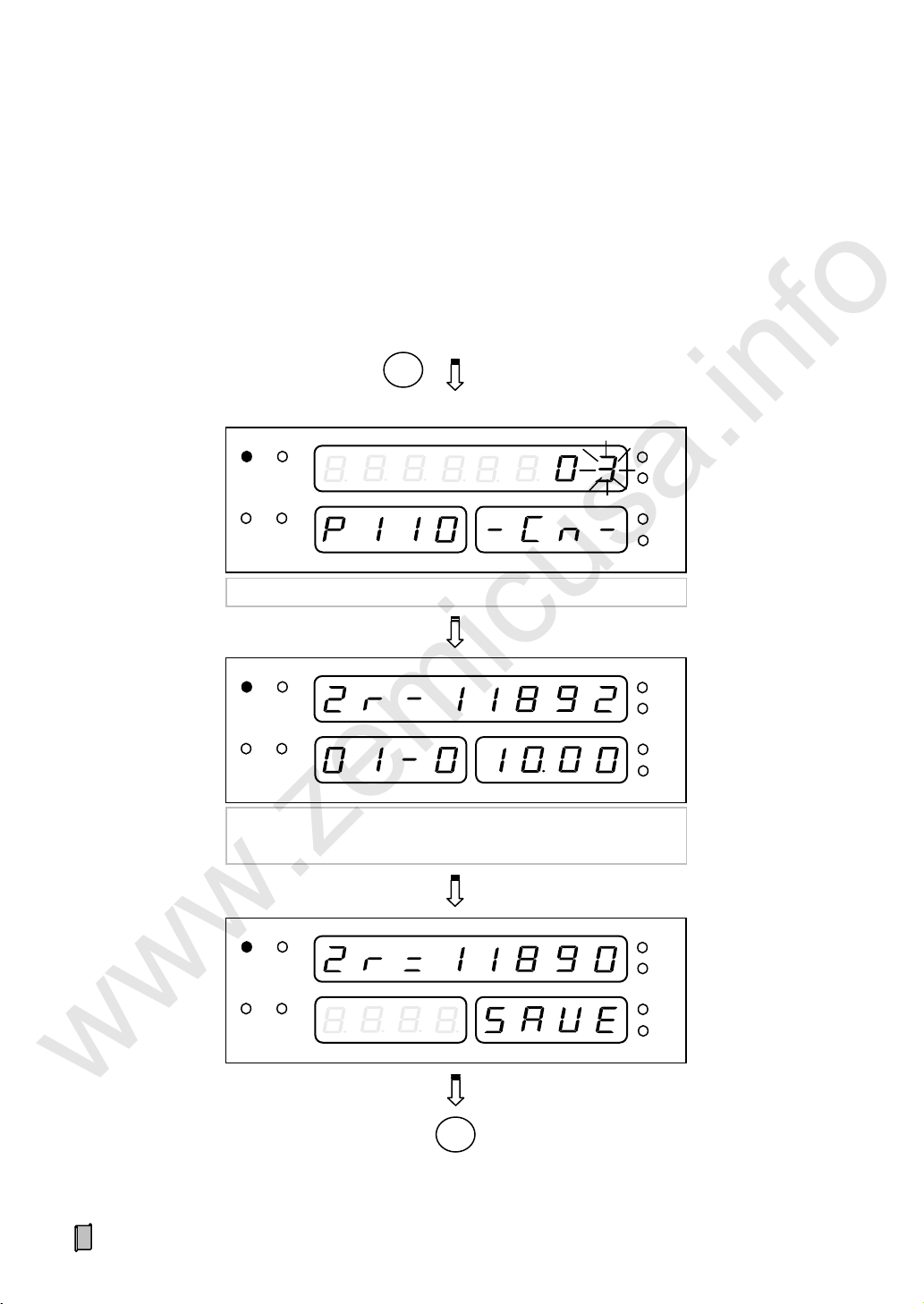
6.4.4 Static Span Calibration with Hanging Weight (HAng)
RUN
AUTO
EXT
ALARM
kg t t/h
kg/m
RUN
AUTO
EXT
ALARM
kg t t/h
kg/m
【ENT】
Input Calibration Revolutions
RUN
AUTO
EXT
ALARM
kg t t/h
kg/m
Input Hanging Weight [kg]
Main Display Interface
【MENU】+【▲】【 ▼】: ≡F2-CAL≡
【ENT】+【▲】【 ▼】: --HAng-【ENT】
M
【ENT】
【ENT】
Input Weigh Length [m]
www.zemicusa.info
Keep the belt weigher running with loading hanging weights for correcting Span Coefficient.
Put a measured hanging weight as a steady load on the belt weigher and then start the belt weigher.
53

RUN
AUTO
EXT
ALARM
kg t t/h
kg/m
RUN
AUTO
EXT
ALARM
kg t t/h
kg/m
【MENU】: Exit 【ENT】: Save
M
【ENT】
RUN
AUTO
EXT
ALARM
kg t t/h
kg/m
【ENT】
Input Calibrating Weight [kg] = Calibration Revolutions × Belt
Length × Hanging Weight / Weigh Length
Totalized Weight; Revolution Count & Remainder length of a
revolution (【▲】【 ▼】: Display Flow or AD value)
AUTO
EXT
ALARM
kg
t
t/h
kg/m
RUN
After running the last revolution
www.zemicusa.info
54

6.4.5 Segmenting Span Correction (SEgC)
Main Display Interface
【MENU】+【▲】【 ▼】: ≡F2-CAL≡
【ENT】+【▲】【 ▼】: --SEgC-【ENT】
M
AD Value Linear Segment: 1~3; SEG1:0~[P119]; SEG2:
[P119]~[P120]; SEG3: [P120]~ Max. AD Value
【ENT】& Start loading
RUN
AUTO
EXT
ALARM
kg t t/h
kg/m
Stop loading & Press【ENT】to run the last revolution:
Totalized Weight; Revolution Count & Remainder length of a
revolution (【▲】【 ▼】: Display Flow or AD value)
RUN
AUTO
EXT
ALARM
kg t t/h
kg/m
After running the last revolution
AUTO
EXT
ALARM
kg t t/h
kg/m
RUN
≡: Running the last revolution
www.zemicusa.info
After doing Dynamic or Static Span Calibration, further corrections for 3 [AD Value: 0~60000] linear
segments are optional for correcting Correction Coefficient 1~3.
55

RUN
AUTO
EXT
ALARM
kg t t/h
kg/m
RUN
AUTO
EXT
ALARM
kg t t/h
kg/m
【MENU】: Exit 【ENT】: Save
M
【ENT】
RUN
AUTO
EXT
ALARM
kg
t
t/h
kg/m
【ENT】
Input Calibrating Weight [kg]
[P121]/[P122]/[P123] Span Correction Coefficient:
0.500~2.000
www.zemicusa.info
56

6.4.6 Speed Calibration (SPEd)
RUN
AUTO
EXT
ALARM
kg t t/h
kg/m
RUN
AUTO
EXT
ALARM
kg t t/h
kg/m
Main Display Interface
【MENU】+【▲】【 ▼】: ≡F2-CAL≡
【ENT】+【▲】【 ▼】: --SPEd-【ENT】
【ENT】
M
Input Belt Length [m]
RUN
AUTO
EXT
ALARM
kg t t/h
kg/m
P: Pulse Count; tI: Run-timer [s]
【MENU】: Exit 【ENT】: Save
M
Run-Timer over
【ENT】
Input Running Time of a Revolution [s]
RUN
AUTO
EXT
ALARM
kg t t/h
kg/m
【▲】【 ▼】:
Display Speed Coefficient [C=] or
Pulse Count [P=]
[P103]: Speed Coefficient [pulse/m]
www.zemicusa.info
Keep the belt weigher running at a constant speed. After the belt running time of a revolution being
measured by stopwatch, do this operation for correcting Speed Coefficient.
57

6.4.7 Belt Length Calibration (LEnS)
RUN
AUTO
EXT
ALARM
kg t t/h
kg/m
Main Display Interface
【MENU】+【▲】【 ▼】: ≡F2-CAL≡
【ENT】+【▲】【 ▼】: --LEnS-【ENT】
【ENT】
M
Input Running Time of a Revolution [s]
RUN
AUTO
EXT
ALARM
kg t t/h
kg/m
L: Belt Length Detected [m]
tI: Run-timer [s]
RUN
AUTO
EXT
ALARM
kg
t
t/h
kg/m
【MENU】: Exit 【ENT】: Save
M
Run-Timer over or【ENT】
[P102]: Belt Length [m]
【▲】【 ▼】: Display Belt Length [L=] or Pulse Count [P=]
www.zemicusa.info
Keep the belt weigher running at a constant speed. After the belt running time of a revolution being
measured by stopwatch, do this operation for correcting Belt Length.
58
6.5 F3-REC Weight Record for Querying&Printing
Main Display Interface
【MENU】+【▲】/【▼】: ≡F3-REC≡
【ENT】
【ENT】
M
RUN
AUTO
EXT
ALARM
kg t t/h
kg/m
Totalized Weight of a Shift, YY.MM.DD-Shift No.1~4
【◄】【 ►】: Previous/next day; 【▲】【 ▼】: Previous/next record
【PRINT】:Print weight records of this shift, See Appendix A.Table 1
RUN
AUTO
EXT
ALARM
kg
t
t/h
kg/m
RUN
AUTO
EXT
ALARM
kg t t/h
kg/m
Totalized Weight of a Day, YY.MM.DD-d
【PRINT】:Print weight records of this day. See Appendix A.Table 2
Input Date
www.zemicusa.info
Weight records per shift/day/month of a year can be queried and printed.
59
【MENU】
M
RUN
AUTO
EXT
ALARM
kg t t/h
kg/m
Totalized Weight from the first day of this month to this day,
【PRINT】: Print weight records (See Appendix A.Table 3)
www.zemicusa.info
60

6.6 F4-CLn Data Clearing
RUN
AUTO
EXT
ALARM
kg t t/h
kg/m
Main Display Interface
【MENU】+【▲】【 ▼】: ≡F4-CLn≡
【ENT】+【▲】【 ▼】: ---CLS--
【ENT】
M
【MENU】: Exit 【ENT】: Enter
M
【▲】【 ▼】:YES/NO
CLS: Clear Screen; CLt: Clear Weight; CLr : Clear Records
www.zemicusa.info
Data Clearing Mode Description:
Manual Clearing Mode
1 Clear Screen: Clear Totalized Weight and Totalized Weight Pulse Count. But Totalized Weight of Current
Shift will not be cleared, so this operation has no effect on recording of weight per shift.
2 Clear Weight: Clear Totalized Weight, Totalized Weight Pulse Count and Totalized Weight of Current
Shift. The cleared value of Totalized Weight of Current Shift will not be recorded.
3 Clear Records: Clear History Records of Totalized Weight. But Current Totalized Weight, Totalized
Weight Pulse Count and Totalized Weight of Current Shift will not be cleared.
Timing Auto Clearing Mode
The parameter „[P606] Auto-clear‟ can be set to „0: OFF / 1: Per Shift / 2: Per Day / 3: Per Month‟, and its
default value is „0: OFF‟.
„Timing Auto Clearing‟ has no effect on recording of weight per shift.
[P606]=„1: Per Shift‟: After recording Totalized Weight per Shift, do operation „Clear Screen‟ automatically.
[P606]=„2: Per Day‟: After recording Totalized Weight of the last Shift per Day, do operation „Clear Screen‟
automatically.
[P606]=„3: Per Month‟: After recording Totalized Weight of the last Shift per Month, do operation „Clear
Screen‟ automatically.
Auto Clearing Before Overflowing Mode
When Totalized Weight value reaches to the maximum value 2×10⁹[Scale Unit], do operation „Clear Screen‟
automatically.
„Auto-clear Before Overflowing‟ has no effect on recording of weight per shift.
61

6.7 F5-SAF Security
RUN
AUTO
EXT
ALARM
kg
t
t/h
kg/m
Main Display Interface
【MENU】+【▲】【 ▼: ≡F5-SAF≡
【ENT】+【▲】【 ▼】: --ALoc-【ENT】+ Input Password +【ENT】
【MENU】: Exit 【ENT】: Enter
M
M
【▲】【 ▼】: 0[OFF] / 1[ON]
RUN
AUTO
EXT
ALARM
kg t t/h
kg/m
Main Display Interface
【MENU】+【▲】【 ▼】: ≡F5-SAF≡
【ENT】+【▲】【 ▼】: --Locc-【ENT】
【MENU】: Exit 【ENT】: Enter
M
M
Input Password
www.zemicusa.info
6.7.1 Auto-locking (ALoc)
Auto-locking: If there is not any keypad operation in one minute and it‟s not in the processes of „F2 Calibration‟ &
„F6 Factory Adj.‟, the controller will lock the keypad and return to „Main Display Interface‟ automatically.
6.7.2 Key-locking (Locc)
62

6.7.3 Key-unlocking (oPEn)
RUN
AUTO
EXT
ALARM
kg t t/h
kg/m
Main Display Interface
【MENU】+【▲】【 ▼】: ≡F5-SAF≡
【ENT】+【▲】【 ▼】: --oPEn-【ENT】
【MENU】: Exit 【ENT】: Enter
M
M
Input Password
www.zemicusa.info
63

6.7.4 Password Set (PASS)
RUN
AUTO
EXT
ALARM
kg t t/h
kg/m
RUN
AUTO
EXT
ALARM
kg t t/h
kg/m
Main Display Interface
【MENU】+【▲】【 ▼】: ≡F5-SAF≡
【ENT】+【▲】【 ▼】: --PASS-【ENT】
【MENU】: Exit 【ENT】: Save
M
M
【ENT】
Input Original Password
Please input and remember the new password
www.zemicusa.info
64
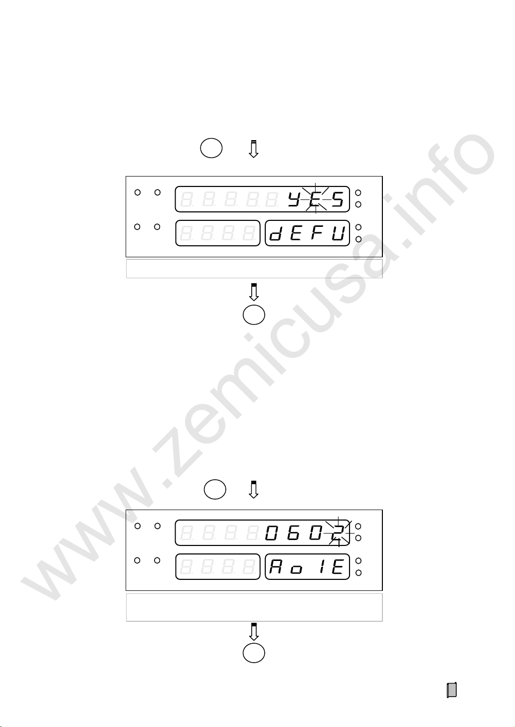
6.7.5 RAM Reset (dEFU)
RUN
AUTO
EXT
ALARM
kg t t/h
kg/m
Main Display Interface
【MENU】+【▲】【 ▼】: ≡F6-FAC≡
【ENT】+【▲】【 ▼】: AoxE(x=1~3)
【ENT】
M
【MENU】: Exit 【ENT】: Save
M
Set AOx Zero value (0~2000)
to make AOx output 4.00mA.
RUN
AUTO
EXT
ALARM
kg
t
t/h
kg/m
Main Display Interface
【MENU】+【▲】【 ▼】: ≡F5-SAF≡
【ENT】+【▲】【 ▼】: --dEFU-【ENT】
【MENU】: Exit 【ENT】: Enter
M
M
【▲】【 ▼】: YES/NO
www.zemicusa.info
6.8 F6-FAC Factory Adjustment
Only after Key-unlocking with the Factory Password, this operation will be valid.
6.8.1 AO Zero Adjustment (AoxE)
65

6.8.2 AO Full Range Adjustment (AoxF)
RUN
AUTO
EXT
ALARM
kg
t
t/h
kg/m
Main Display Interface
【MENU】+【▲】【 ▼】: ≡F6-FAC≡
【ENT】+【▲】【 ▼】: AI1E
【ENT】
M
【MENU】: Exit 【ENT】: Save
M
Input 4.00mA from AI port to correct AI zero value (0~2000)
RUN
AUTO
EXT
ALARM
kg t t/h
kg/m
Main Display Interface
【MENU】+【▲】【 ▼】: ≡F6-FAC≡
【ENT】+【▲】【 ▼】: AoxF(x=1~3)
【ENT】
M
【MENU】: Exit 【ENT】: Save
M
Set AOx Full value (2000~4095)
to make AOx output 20.00mA.
www.zemicusa.info
6.8.3 AI Zero Adjustment (AI1E)
66

6.8.4 AI Full Range Adjustment (AI1F)
RUN
AUTO
EXT
ALARM
kg t t/h
kg/m
Main Display Interface
【MENU】+【▲】【 ▼】: ≡F6-FAC≡
【ENT】+【▲】【 ▼】: AI1F
【ENT】
M
【MENU】: Exit 【ENT】: Save
M
Input 20.00mA from AI port to correct AI full value (2000~4095)
RUN
AUTO
EXT
ALARM
kg t t/h
kg/m
Main Display Interface
【MENU】+【▲】【 ▼】: ≡F7-INF≡
【ENT】+【▲】【 ▼】: ---VEr-【ENT】
VEr : Version No.; Sn: Serial No.; dAtE: Exfactory Date
AudIt: Audit Counter; AutH: Authorization Code
【MENU】
M
M
www.zemicusa.info
6.9 F7-InF Product Information
67
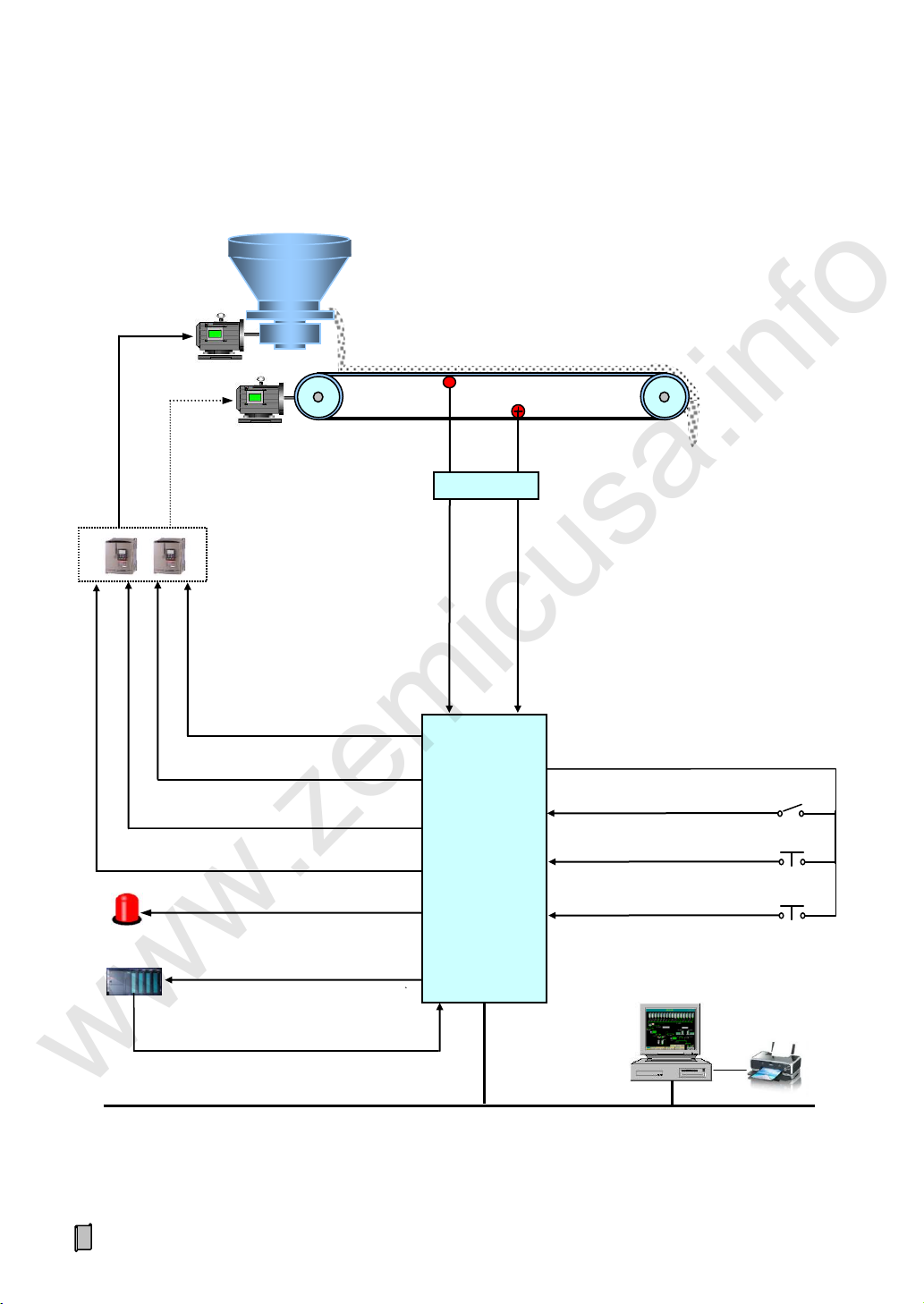
AI.Flow Setpoint
Frequency Convertor
& Relays
AO.Corntrol Current
IPC/ PLC
RS485/RS232/RS422/Profibus-DP/CANBUS
AO.Corntrol Current
DO.Feeder Control
DO.Belt Weigher Control
AO.Flow
PLC/IPC
DI/DO/AO: Definable.
AO3: If you need it, inform us in your order.
Belt Weigher
Speed Sensor
Feeder
Loadcell
Weighing Signal
Speed Signal
Summing Box
DI. Start
COM
DI. System Ready
DI. Stop
Diverter Switch
Reset Button
DO.Alarm
Controller
www.zemicusa.info
7. Ration Flow Auto-Feeding System
68

Appendix A. Print Formats
Table 1. Weight Record For A Shift (SW)
WEIGHT RECORD
-------------------------DATE: 2009-05-20
NAME: SW
TW: 109980kg
-------------------------2009-05-20 23:59
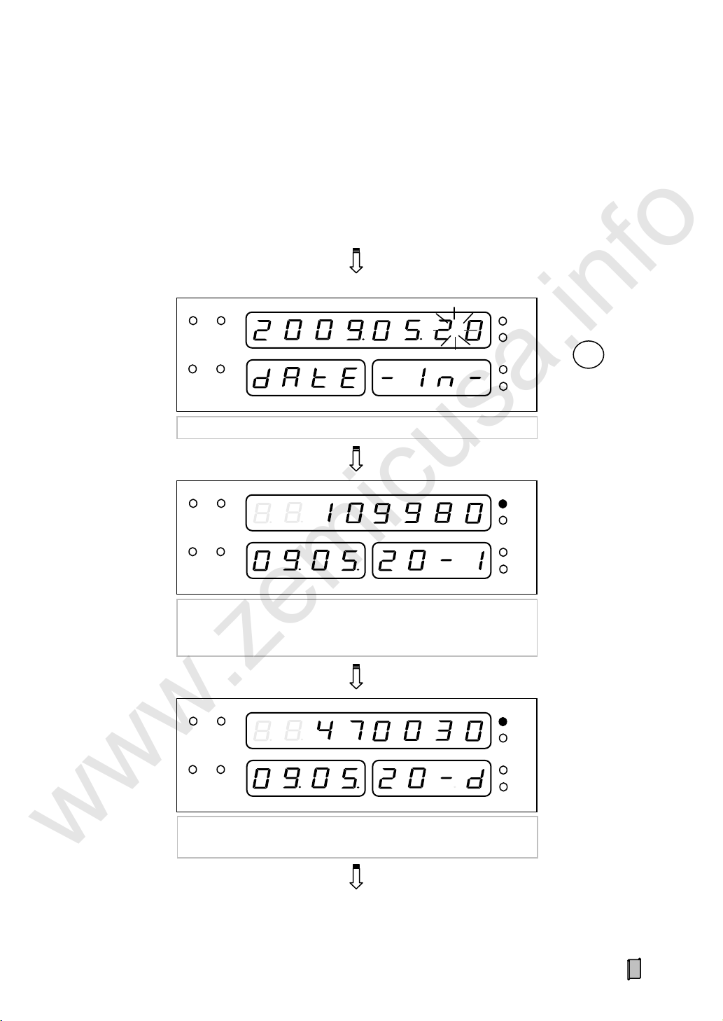
Table 2. Weight Record For A Day (DW)
WEIGHT RECORD
-------------------------DATE: 2009-05-20
NAME: 1W
TW: 109980kg
DATE: 2009-05-20
NAME: 2W
TW: 169900kg
DATE: 2009-05-20
NAME: 3W
TW: 190150kg
DATE: 2009-05-20
NAME: DW
TW: 470030kg
-------------------------2009-05-20 23:59
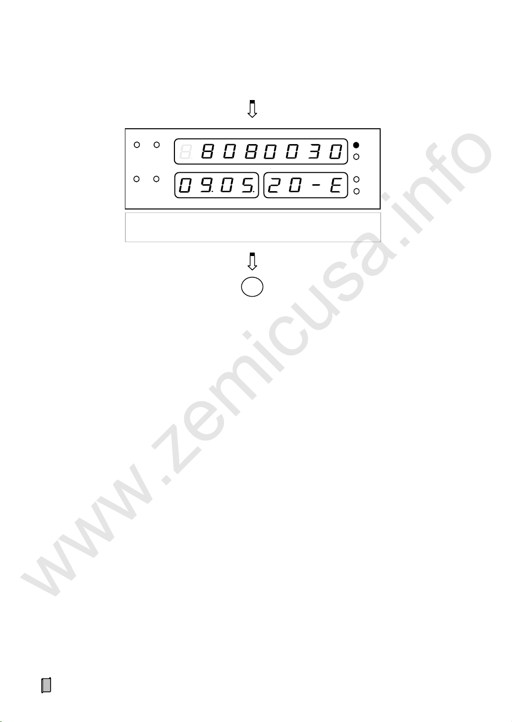
Table 3. Weight Record For A Month (MW)
WEIGHT RECORD
-------------------------DATE: 2009-05-01
NAME: DW
TW: 387090kg
DATE: 2009-05-02
NAME: DW
TW: 568800kg
。。。 。。。
DATE: 2009-05-20
NAME: DW
TW: 470030kg
DATE: 2009-05-20
NAME: MW
TW: 8080030kg
-------------------------2009-05-20 23:59
www.zemicusa.info
Print Format A:
69

Print Format B:
www.zemicusa.info
Table 1. Weight Record For A Shift (SW)
WEIGHT RECORD
-------------------------------------------------DATE NAME WEIGHT
2009-05-20 SW 109980kg
-------------------------------------------------2009-05-20 23:59
`
Table 2. Weight Record For A Day (DW)
WEIGHT RECORD
--------------------------------------------------
DATE NAME WEIGHT
2009-05-20 1W 109980kg
2009-05-20 2W 169900kg
2009-05-20 3W 190150kg
2009-05-20 DW 470030kg
--------------------------------------------------
2009-05-20 23:59
Table 3. Weight Record For A Month (MW)
WEIGHT RECORD
--------------------------------------------------
DATE NAME WEIGHT
2009-05-01 DW 387090kg
2009-05-02 DW 568800kg
2009-05-03 DW 190150kg
。。。 。。。 。。。
2009-05-20 DW 470030kg
2009-05-20 MW 8080030kg
--------------------------------------------------
2009-05-20 23:59
Appendix B. Communication Protocols
If you need the communication protocols, please contact us.
70

User’s Memo
www.zemicusa.info
71

www.zemicusa.info
Changsha Supmeter Technological Co.,Ltd.
Address: Building A6, Lugu International Industrial Park,
Changsha, 410205, China
Tel: +86 731 85115100
Fax: +86 731 85158100
Website: www.supmeter.com.cn
E-mail: supmeter@163.com
 Loading...