

Page 1
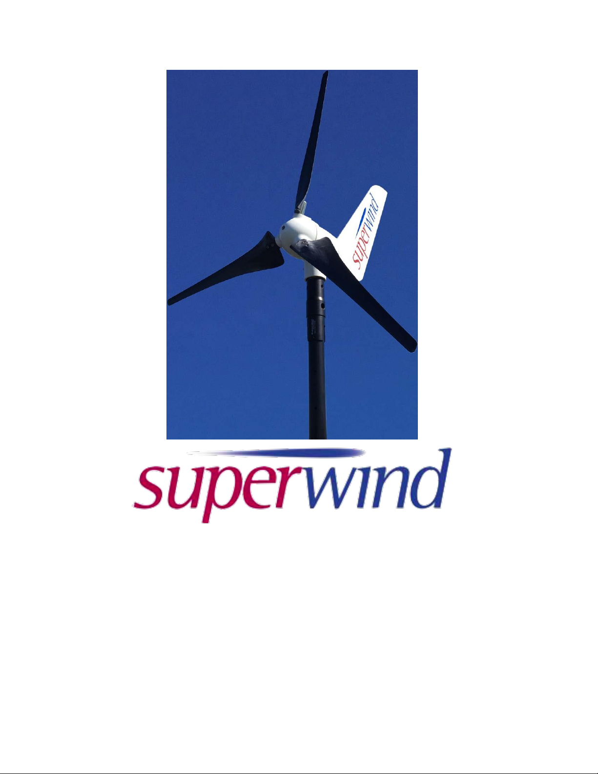
Superwind 350 / 48 Volt
Operation Manual
North, Central, South America and the Caribbean Regions
Version 1-2019
www.superwind.com
Page 2

1
THIS PAGE INTENTIONALLY LEFT BLANK
© Copyright Mission Critical Energy Inc, 2019 Version 1-2019
www.superwind.com
Page 3
2
Indicates critical information regarding a hazardous situation that
could lead to serious personal injury or death if ignored.
Indicates a potentially hazardous situation that could lead to
serious personal injury or death if ignored.
Indicates pertinent or otherwise useful information on a given topic
or procedure.
INSTALLATION
PLEASE DO NOT PROCEED
UNTIL YOU HAVE READ
ALL INSTRUCTIONS
AND SAFETY INFORMATION
Thank you for purchasing a
Superwind 350/48V
The Superwind 350/48V is an advanced wind generator of the highest quality that will reliably
generate power for many years. Reliable operation depends not only on product quality however, but
also on correct assembly and installation. Please read this manual in its entirety before starting your
installation, paying particular attention to all safety instructions and warning notices. Your safety is our
highest priority!
MEANING OF SYMBOLS USED IN THIS MANUAL
All information provided in this manual is believed to be accurate at time of publication,
Member of:
however superwind GmbH assumes no responsibility for errors or omissions.
The user of this information and product assumes full responsibility and risk.
All specifications are subject to change without notice.
KEEP THIS MANUAL ACCESSIBLE FOR FUTURE REFERENCE
© 2018 superwind GmbH.
Superwind is a Registered Trade Mark of superwind GmbH, Germany
VERSION 1-2019
(Please visit www.missioncriticalenergy.com to verify the latest manual version)
© Copyright Mission Critical Energy Inc, 2019 Version 1-2019
www.superwind.com
Page 4

3
Table of Contents
Section Description Page No.
OVERVIEW ................................................................................................................. 2
TABLE OF CONTENTS .............................................................................................. 3
1. GENERAL INFORMATION AND REFERENCES ..................................................... 6
1.1 Company Profile .......................................................................................................... 6
1.2 Labeling ....................................................................................................................... 6
1.3 Range of Application ................................................................................................... 7
2. WARRANTY .............................................................................................................. 7
2.1 Warranty ...................................................................................................................... 7
2.2 Warranty period ........................................................................................................... 7
2.3 To obtain warranty service .......................................................................................... 7
2.4 Limitations ................................................................................................................... 8
2.5 Others ......................................................................................................................... 8
2.6 Expenses and Responsibilities ................................................................................... 8
2.7 Claims ......................................................................................................................... 9
3. SAFETY INSTRUCTIONS .......................................................................................... 9
3.1 Potential hazards ........................................................................................................ 9
3.1.1 Mechanical hazards ..........................................................................................9
3.1.2 Electrical hazards .............................................................................................9
3.1.3 Hazards when mounting the wind turbine ...................................................... 10
3.1.4 General safety precautions ............................................................................. 10
4. TECHNICAL SPECIFICATIONS .............................................................................. 11
4.1 Operational free space required ................................................................................ 11
4.1.1 Main dimensions ............................................................................................. 11
4.2 Technical data ............................................................................................................ 11
4.3 Functional description / Special features ................................................................... 12
5. PREPARATIONS FOR ASSEMBLY ........................................................................ 13
5.1 Inspection and Unpacking .......................................................................................... 13
5.1.1 Inspection ....................................................................................................... 13
5.1.2 Unpacking ....................................................................................................... 13
5.1.3 Packing List .................................................................................................... 13
5.2 Tools .......................................................................................................................... 14
5.3 Available accessories................................................................................................. 14
5.4 Electrical components ................................................................................................ 14
5.5 Shipping ..................................................................................................................... 15
5.5.1 Measurements ................................................................................................ 15
5.5.2 Weight ............................................................................................................. 15
5.5.3 Shipping Class and HB Number ..................................................................... 15
6. ELECTRICAL COMPONENTS AND CONNECTIONS ............................................ 15
6.1 General information.................................................................................................... 15
6.2 Wiring Diagram .......................................................................................................... 15
6.3 System components................................................................................................... 16
© Copyright Mission Critical Energy Inc, 2019 Version 1-2019
www.superwind.com
Page 5

4
6.3.1 Wires ............................................................................................................... 16
AWG Wire Size Chart Table No. 6.3.1 ........................................................... 17
6.3.2 Strain relief...................................................................................................... 17
6.3.3 Polarity ............................................................................................................ 18
6.3.4 Batteries .......................................................................................................... 18
6.3.4.1 Charging the batteries ...................................................................... 18
6.3.4.2 Selecting the batteries ..................................................................... 18
6.3.4.2.1 Battery Capacity .............................................................. 19
6.3.4.3 Protection ........................................................................................ 19
6.3.5 Charge Regulator SCR 48 V .......................................................................... 20
6.3.5.1 Technical data .................................................................................. 20
6.3.5.2 Functional description ...................................................................... 21
6.3.5.3 Installation location .......................................................................... 21
6.3.5.4 Connecting the Charge Regulator ................................................... 21
6.3.5.5 Wiring diagrams ............................................................................... 23
6.3.6 Fuses .............................................................................................................. 23
6.3.7 Stop Switch ..................................................................................................... 24
6.3.7.1 Mounting .......................................................................................... 24
6.3.7.2 Dimensions ...................................................................................... 24
6.3.7.3 Electrical Connection ....................................................................... 25
6.3.7.4 Switch Terminals .............................................................................. 26
6.3.7.5 Component locations ....................................................................... 27
6.3.8 Diversion Load Power Resistor ...................................................................... 27
6.3.9 Temperature Sensor ....................................................................................... 27
6.4 Grounding .................................................................................................................. 27
7. SUPERWIND 350/48V GENERATOR ASSEMBLY ................................................ 28
7.1 Precautions ................................................................................................................ 28
7.1.1 Short Circuit .................................................................................................... 28
7.2 Delrin® Bushings ........................................................................................................ 29
7.2.1 Bushing Basics ............................................................................................... 29
7.2.2 Bushing Types ................................................................................................ 29
Bushing Quick Guide Chart .......................................................................... 31
7.2.2.1 American Delrin® White ................................................................... 31
7.2.2.2 American Delrin® Black ................................................................... 32
7.3 Mast mounting ............................................................................................................ 32
7.3.1 Mounting on a 60.3 mm or 60.0 mm mast tube ............................................. 33
7.3.1.1 Preparations at the mast head ......................................................... 33
7.3.2 Mounting on a 48.3 mast tube ........................................................................ 35
7.3.2.1 Preparations at the mast head ......................................................... 35
7.3.3 Mounting on other mast tubes ........................................................................ 35
7.3.3.1 Preparations at mast head ............................................................... 36
7.3.4 Mast Tube Specifications ............................................................................... 36
7.4 Rotor Blades .............................................................................................................. 36
7.4.1 Mounting on the wind vane ............................................................................. 37
7.5 Rotor Assembly .......................................................................................................... 37
7.5.1 Attaching the rotor blades to the hub ............................................................. 38
7.5.2 Mounting the hub to the generator shaft ........................................................ 39
© Copyright Mission Critical Energy Inc, 2019 Version 1-2019
www.superwind.com
Page 6

5
8. COMMISSIONING ................................................................................................... 40
8.1 Check list .................................................................................................................... 40
9. OPERATION ............................................................................................................. 41
9.1 Safety Instructions...................................................................................................... 41
9.2 RUN and STOP .......................................................................................................... 41
9.3 Power Control ............................................................................................................ 41
9.4 Over-Speed Protection .............................................................................................. 42
9.5 Annual Power Production .......................................................................................... 42
10. INSPECTIONS AND MAINTENANCE ..................................................................... 43
10.1 Periodic Inspections ................................................................................................... 43
10.1.1 Rotor Blades ................................................................................................... 43
10.1.2 Bolted Connections ........................................................................................ 43
10.1.3 Bearings .......................................................................................................... 43
10.1.4 Slip Rings ........................................................................................................ 44
10.1.5 Corrosion Protection ....................................................................................... 44
10.1.6 Mast ................................................................................................................ 44
10.1.7 Electrical system ............................................................................................. 44
10.2 Maintenance ............................................................................................................... 45
11. TROUBLE SHOOTING ............................................................................................ 45
11.1 Wind Generator does not start ................................................................................... 45
11.2 No power output ......................................................................................................... 46
11.3 Low power output ....................................................................................................... 46
11.4 Battery fails to (fully) charge ...................................................................................... 47
11.5 Checking open circuit voltage .................................................................................... 47
12. REPAIRS AND RECOMMENDED SPARE PARTS ................................................ 47
12.1 Repairs ....................................................................................................................... 47
12.2 Spare parts list ........................................................................................................... 48
13. FREQUENTLY ASKED QUESTIONS ........................................................................ 48
13.1 Basic use .................................................................................................................... 48
13.2 Installation .................................................................................................................. 48
13.3 Operation ................................................................................................................... 49
13.4 Trouble shooting ........................................................................................................ 50
14. ABBREVIATIONS ...................................................................................................... 51
15. SCOPE OF CHANGES............................................................................................... 52
© Copyright Mission Critical Energy Inc, 2019 Version 1-2019
www.superwind.com
Page 7
6
1.
GENERAL INFORMATION AND REFERENCES
1.1 Company profile
superwind GmbH was established in 2004 after four years of successful research,
design and testing of its now internationally patented micro-turbine technology. Since
then, thousands of commercially rated Superwind 350, Superwind 353 and
Superwind 1250 turbines have been quietly providing reliable, autonomous wind
generated electricity to users in remote locations under harsh conditions on both land
and sea world-wide.
As your satisfaction is as important as our reputation, we thank you in advance for
reading this Superwind manual in its entirety prior to installing (or even purchasing)
our wind generating equipment. We also wish to remind you that wind turbines work
best when installed where there is sufficient wind, so please research your planned
wind turbine site or vessel installation to help accurately predict how a Superwind
turbine can help with you power needs.
On behalf of our Superwind staff and world joint venture partners, we thank you for
your interest in our cutting edge, real-world proven wind turbines.
1.2 Labeling
This manual refers to our Superwind 350/48V wind generator.
Manufacturer:
superwind GmbH
Am Rankewerk 2-4
D-50321 Brühl
Germany
Tel.: +49 / 2232 / 577357
Fax: +49 / 2232 / 577368
E-Mail: [email protected]
Internet: www.superwind.com
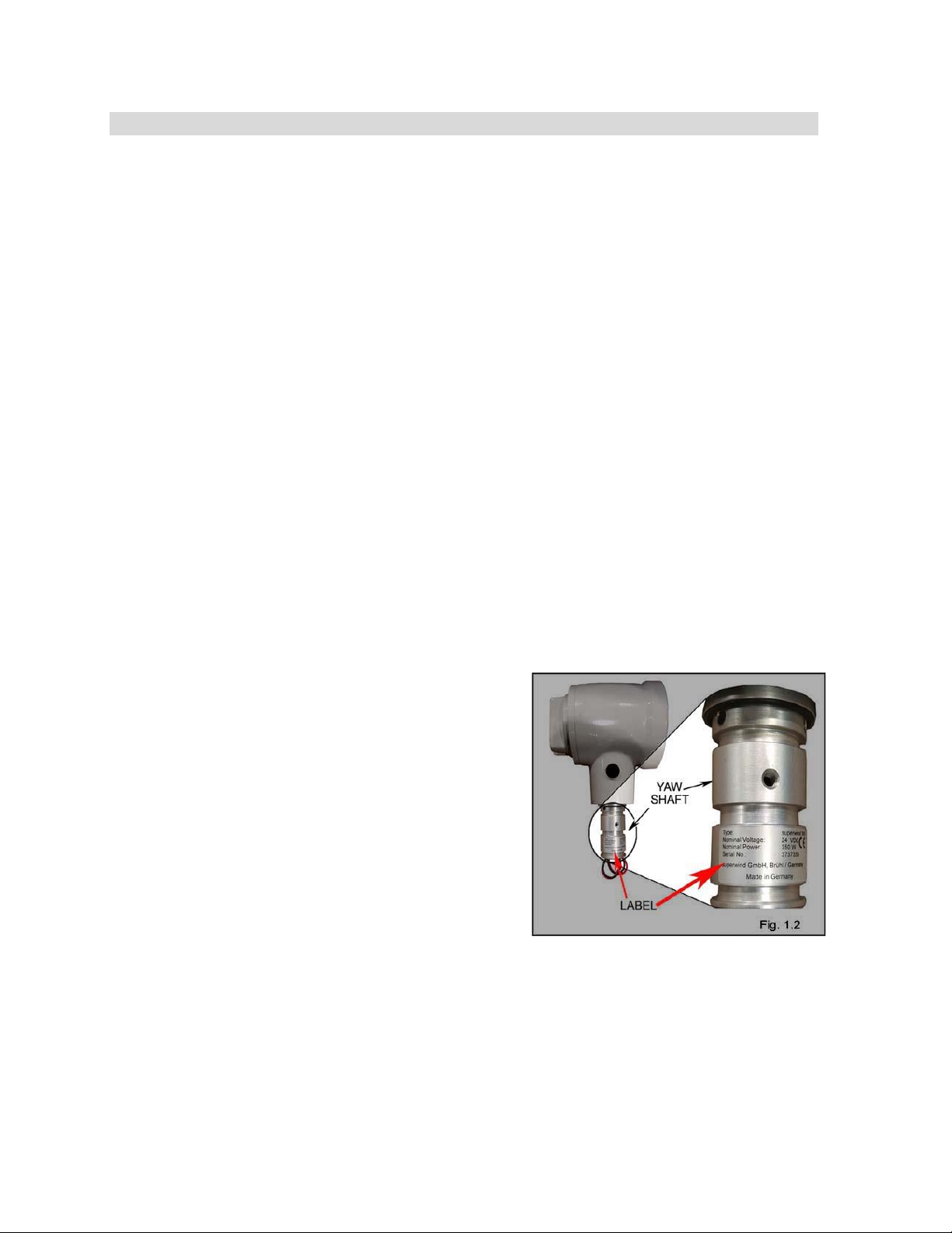
The data tag listing the serial number and
nominal voltage of your the Superwind
350/48V is located on the yaw shaft. (Fig
No. 1.2).
The Intent of this manual is to assist
technicians with the professional
installation of the Superwind 350/48V
in order to ensure the system is both installed correctly and operational as quickly as
possible.
For future reference, please record the Serial Number of your Superwind 350/48V in
the space provided below prior to installation. Once the yaw shaft is inserted into the
bushing and into the mast, this information will not be visible.
Type ........................................................ Superwind 350/48V
Serial Number ........................................ ___________________
© Copyright Mission Critical Energy Inc, 2019 Version 1-2019
www.superwind.com
Page 8

7
2.
WARRANTY
1.3 Range of application
The electrical power generated by the Superwind 350/48V is used primarily to charge
batteries and/or directly power 48 VDC appliances. AC appliances can be powered via
an optional inverter. There is a wide range of high quality, 48 VDC equipment
available. Examples include energy saving lamps, refrigerators, deep-freezers, water
pumps, ventilators, consumer electronics, TV, radio and navigation equipment, etc.
Ideal applications for the Superwind 350/48V range from commercial and government
needs (navigational aids, traffic management systems, monitoring stations and
transmitters) to private sector use, such as mountaintop cabins or other remote, offgrid locations.
The Superwind 350/48V is also fully compatible with installations utilizing solar
arrays. At many locations, wind and solar energy complement each other. A hybrid
wind / solar dual charging system featuring the Superwind 350/48V allows you to
optimise available energy sources, while requiring minimal battery capacity.
2.1 Warranty
superwind GmbH warrants this product to be in good working order during the
warranty period. In the event that the product is found to be defective within the
warranty period, repair service will be provided free of charge by superwind GmbH or
an authorized service partner.
Warranty covered repairs may be obtained only upon presentation of the warranty
card and the original invoice issued to the customer by the retailer. The warranty card
must state the buyer’s name, the retailer’s name and address, the serial number and
purchase date of the product. superwind GmbH reserves the right to refuse warranty
service if this information is not complete or has been removed or changed after the
original purchase of the product by the purchaser from the retailer.
2.2 Warranty period
The warranty period is three years from the date of purchase, as provided by the
above mentioned documents.
2.3 To obtain warranty service
Warranty service is available at superwind GmbH and all Superwind authorized
service partners. All costs associated with transportation of the product to and from
superwind GmbH or Superwind authorized service partners will be borne by the
customer.
© Copyright Mission Critical Energy Inc, 2019 Version 1-2019
www.superwind.com
Page 9

8
2.4 Limitations
superwind GmbH does not warrant the following:
Periodic check-ups, maintenance and repair or replacement of parts due to
normal wear and tear.
Defects caused by modifications carried out without Superwind’s express written
approval.
Defects caused by improper use, handling or operation and in particular defects
caused by improper installation or installation on inadequate masts or support
structures.
To obtain warranty service, the purchaser must provide evidence upon request
that the product has been installed on an adequate mast or support structure.
Accidents, disasters or any cause beyond the control of superwind GmbH,
including but not limited to lightning, flooding, fire, acts of war, vandalism, etc.
Costs for disassembly and reassembly of the product to enable shipment for
warranty reasons.
2.5 Others
superwind GmbH reserves the right to decide whether the product or parts of the
original Superwind system shall be repaired or replaced. Should repair or replacement
by superwind GmbH not be possible, the original purchaser will be entitled to a full
refund from the manufacturer; superwind GmbH. This refund is limited to the
purchase price of the product only and does not include any associated expenses,
such as shipping, installation, bank fees, etc.
This warranty does not affect the purchaser’s statutory rights under applicable national
legislation in force, nor the buyer’s right against the retailer arising from the sales /
purchase contract. In the absence of applicable national legislation, this warranty will
be the purchaser’s sole and exclusive remedy and superwind GmbH shall not be
liable for any incidental or consequential damages for breach of any expressed or
implied warranty of this product.
In addition to the above warranty coverage, the GENERAL CONDITIONS FOR THE
SUPPLY OF PRODUCTS AND SERVICES OF THE ELECTRICAL AND
ELECTRONICS INDUSTRY produced by the German Federation of the Electric and
Electronic Industry (ZVEI) also applies.
2.6 Expenses and Responsibilities
All associated expenses (shipping to and from the repair facility, insurance, etc) are
the full responsibility of the buyer or his shipping agent, unless the buyer is notified
otherwise by the manufacturer.
Upon receipt of your unit:
Inspect the outside of the shipping package or container for any damage (dents,
scratches, etc,). Document any damage noted on the Bill of Lading before signing
and keep a copy. Documenting damage with photos is also highly recommended.
Open the crate and inspect the contents immediately for any damage.
Unpack the unit immediately and perform a visual inspection to determine if it is
dented, bent or scratched.
If for any reason the unit should need to be returned, the original crate is the
best way to ship it back to the manufacturer.
© Copyright Mission Critical Energy Inc, 2019 Version 1-2019
www.superwind.com
Page 10
9
3
SAFETY INSTRUCTIONS
2.7 Claims
Claims that occur during transportation must be filed by the consignee (the buyer) with
the freight company, as shipping terms are FOB EX-WORKS (our distribution point as
contracted).
THE BUYER IS RESPONSIBLE FOR ALL SHIPPING EXPENSES, INCLUDING
CUSTOMS DUTIES AND VAT (IMPORT DUTIES).
Please read this manual thoroughly prior to assembly and installation of your Superwind
350/48V. The information provided is to ensure your safety during assembly, mounting and
operation, as well as during maintenance and troubleshooting. If you have any additional
questions please contact your dealer, a Superwind service partner or the manufacturer.
3.1 Potential Hazards
There are a number of potential physical and electrical hazards associated with the
installation and operation of a wind turbine. Familiarity with safety practices and
procedures beforehand is crucial, both in avoiding injury to personnel and damage to
the Superwind 350/48V wind turbine.
3.1.1 Mechanical Hazards
The main physical hazard is contact with a spinning rotor. The rotor blades can cause
serious injury, even at very low speed.
Never touch the rotor blades while moving!
Never try to stop the rotor by hand!
Never mount the rotor in a location where it can accidentally come into contact
with personnel!
The rotor blades are constructed of glass fibre and carbon fibre reinforced plastic.
This material is extremely durable (which enables your Superwind 350/48V to cope
with heavy storms) however it can break if objects strike the rotor at higher rotational
speeds.
Never allow objects to come in contact with the rotor while in operation!
3.1.2 Electrical Hazards
Even at low wind speeds, the generator can produce dangerous open circuit voltages
(up to 210 VDC) at no-load operation (i.e. with the electric connection to the battery
disconnected).
Charging currents can reach up to 7.5 Amps DC. As such, all cabling, electrical
components and connectors must be rated to 10 Amps. For correct wiring
dimensioning refer to Section 6.3.
The use of undersized cabling can result in overheating and failure, possibly
creating fire and shock hazards!
© Copyright Mission Critical Energy Inc, 2019 Version 1-2019
www.superwind.com
Page 11
10
Never short-circuit the battery, which can result in fire or explosion of
the battery, along with release of acid and toxic gases.
These instructions also apply to future disassembly, inspections or other
work carried out on your wind generator.
Fuses are installed to protect the wiring of the system and must be installed as close
to the battery as possible. For details see Section 6.3.6.
Unsealed lead-acid batteries produce and vent flammable hydrogen gas during
charging. This creates an explosive mixture that can easily be detonated by even the
smallest of sparks (those produced by an electrical switch for example).
To reduce the possibility of explosion, always ensure battery installations are provided
adequate ventilation.
Never install batteries in locations where the danger of sparks exist.
Provide sufficient ventilation for battery storage areas at all times.
The diversion load power resistor for the charge regulator can become hot. To
prevent the possibility of fire, never mount the power resistor on a flammable
surface or close to flammable materials.
Never mount the power resistor on a flammable surface.
Mount the power resistor at least 40mm (1.57”) away from any flammable
materials
3.1.3 Hazards when mounting the wind turbine
Use only mast and support designs capable of safely handling the loads associated
with the installation of your Superwind 350/48V. The mast not only has to support
your wind generator’s weight, but also the considerable thrust generated by high wind
speeds. For details see Section 7.3.
3.1.4. General safety precautions
Conduct all work on the mast or wind generator only on a calm, windless day.
Do not allow personnel to walk or stand beneath hanging loads or potential drop
hazards (such as a tilted mast).
Disconnect all batteries from the system prior to beginning any work.
To prevent your wind generator from starting unintentionally, place the stop switch
into the STOP position or short circuit the generator output wires (Red and Black)
before mounting the rotor blades.
Do not install the wind generator in areas where it can be easily reached or
approached by anyone walking by or working around the turbine structure.
© Copyright Mission Critical Energy Inc, 2019 Version 1-2019
www.superwind.com
Page 12
11
4.
TECHNICAL SPECIFICATIONS
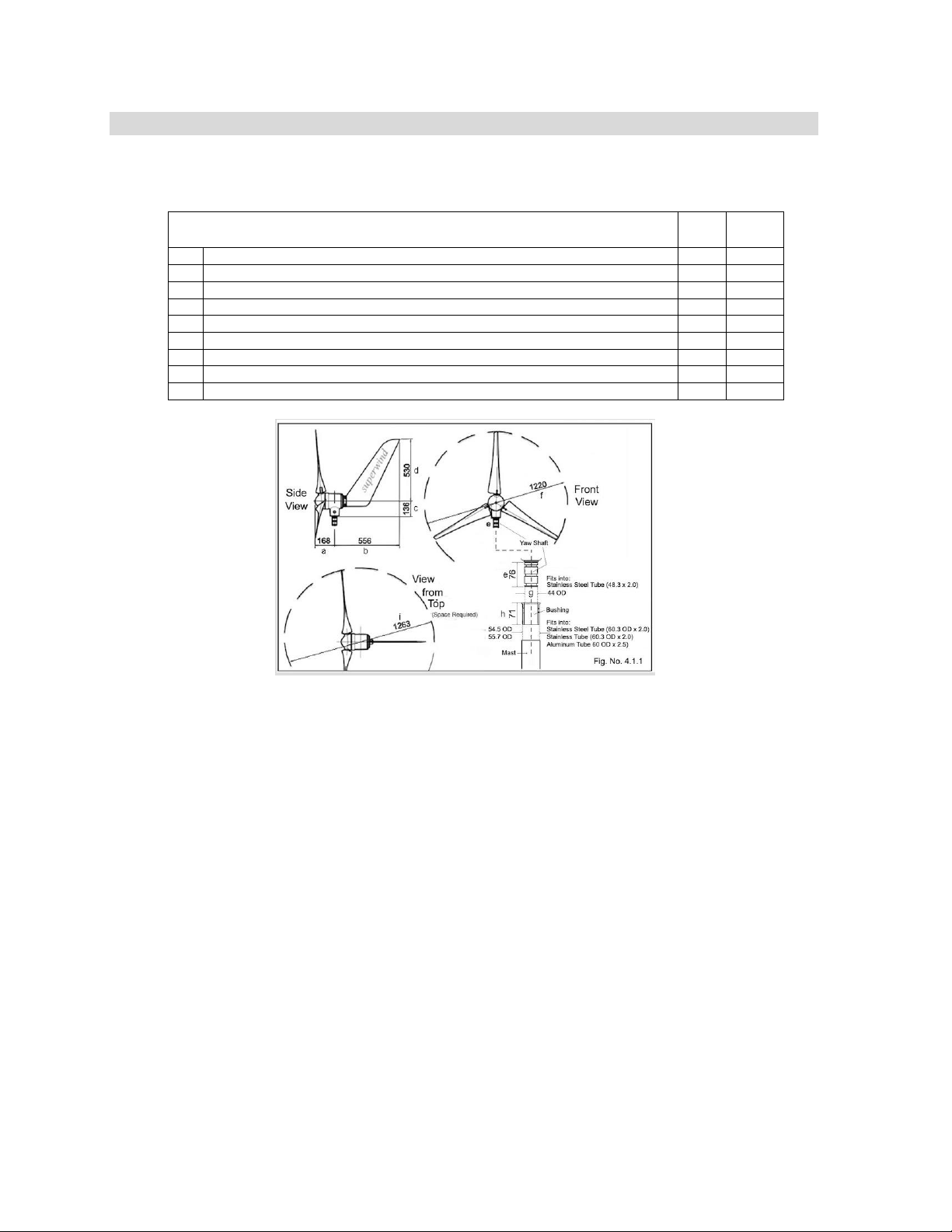
Dimensions
Table No. 4.1.1
mm
inches
a
Distance between centre of mast and blade tip
168
6.61”
b
Distance between centre of mast and extreme upper part of wind vane
556
21.9”
c
Distance from mast-top to centre of rotor
136
5.35”
d
Distance from the centre of hub and extreme upper part of the wind vane
530
20.9”
e
Length of yaw shaft
76
2.99”
f
Rotor diameter including blades
1220
48”
g
Outside diameter (OD) of yaw shaft with damping rings
44
1.73”
h
High for Plastic Bushing to be inserted into mast
71
2.79”
i
Required space for yawing
1263
49.72”
4.1 Operational free space required
4.1.1 Main dimensions
4.2 Technical Data
Nominal power ..................................................... 350 W
Nominal wind speed ............................................. 12.5 m/s (24.29 knots)
Cut in wind speed ................................................. 3.5 m/s (6.80 knots)
Cut off wind speed................................................ None
Rotor diameter ...................................................... 1,20 m (47.24”)
Number of blades ................................................. 3
Blade material ...................................................... Carbon fibre reinforced plastics
Rotor speed .......................................................... 500 – 1300 rpm
Generator ............................................................ Permanent magnet 3-phase with
rectifier neodymium magnets
Nominal voltage.................................................... 48 V DC
Speed regulation .................................................. Rotor blade pitch
Power regulation .................................................. Rotor blade pitch
Brake .................................................................... Generator short circuit
Weight .................................................................. 11.5 kg (25.35 lb)
Rotor thrust (operation) ........................................ 70 N (15.7 lbf)
Rotor thrust (extreme wind speed) ....................... 220 N (49.5 lbf)
© Copyright Mission Critical Energy Inc, 2019 Version 1-2019
www.superwind.com
Page 13

12
Optimum start-up performance will be reached after a break-in
period of the bearings and their seals. The duration of the break-in
period can vary depending on site wind conditions
4.3 Functional description / special features
Like all wind turbines, the Superwind 350/48V uses the kinetic energy of the wind to
generate electricity. The power generated is approximately proportional to the cube of
the wind speed (i.e. doubling the wind speed results in eight times the power output).
This means that relatively little energy can be generated during the varying wind
speeds of a moderate breeze. A heavy storm however, contains such a high quantity
of energy that the wind generator must be protected against overstress and damage.
The Superwind 350/48V has been designed to achieve optimum power output for a
wide range of wind speeds while providing maximum safety and survivability during
storm conditions.
a) The rotor blades were developed using modern computerized calculation and
simulation methods. The airfoil has been wind tunnel tested and specifically
developed for small size rotors. Relatively broad rotor blades combined with a
special pitch angle produces a high start-up torque, enabling the rotor to start
turning at only 3.5 m/s (7.8 mph) of wind speed.
When using the Superwind 350/48V for battery charging, do not confuse the initial rotor
start-up voltage for the output charging voltage. The wind speed required to start
charging depends on the battery’s state of charge and may be slightly higher than the
rotor start-up wind speed.
b) A key innovation of the Superwind 350/48V is its patented aerodynamic rotor
control system, which (similar to large wind turbines) automatically adjusts the
pitch angle of the rotor blades based on wind speed. The mechanical controller is
fully integrated into the hub and works without expensive, failure-prone electrical
or hydraulic components. Instead, the controller is actuated by forces arising
from operation of the wind turbine itself. These forces are affected by the
geometric and kinematic lay-out of the rotor controller mechanism.
Aerodynamic forces act as control variables to automatically adjust the rotor blades for
power regulation above the nominal operating wind speed of the unit. Simultaneously,
centrifugal forces (the second control variable of the rotor blade adjustment) are
introduced and as both the wind force and rotor speed decrease or increase, the
controller automatically limits rotor speed. This occurs even at extreme wind velocities.
This unique system is crucial in protecting the wind turbine from over-speed conditions,
even during no-load operation. As a result, the controller limits the mechanical loads at
high wind speeds and enables smooth operation under all weather conditions.
© Copyright Mission Critical Energy Inc, 2019 Version 1-2019
www.superwind.com
Page 14
13
5.
PREPARATIONS FOR ASSEMBLY
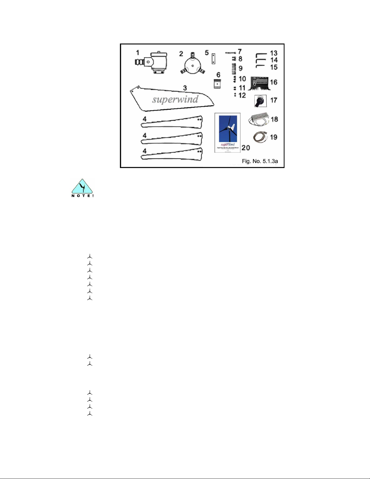
PACKING LIST
Table 5.1.3
ITEM
DESCRIPTION
SIZE
QTY
1
Generator unit
48V
1
2
Hub 1
3
Wind vane
1
4
Rotor blade
3 5
Wind vane mounting plate
1
6
Plastic bushing (optional stainless steel bushing)
1
7
Socket cap bolt – [Rotor Hub Mounting Bolt]
M8 x 80
1 8
Socket cap bolt
M8 x 20
2
9
Socket cap bolt
M6x 25 (TUFLOK)
6
10
Socket cap screw with rubber ring
M6 x 8 (TUFLOK)
3
11
Hexagon socket button head screw
M6 x 12
2 12
Hexagon socket button head screw
M6 x 6
2 13
Allen key
6 mm
1 14
Allen key
5 mm
1 15
Allen key
4 mm
1 16
SCR 48V Charge Regulator
1
17
Stop Switch
1
18
Power resistor
5.6 Ohm, 400 Watt
1 19
Temp-Sensor
1 20
Operation manual
1
5.1 Inspection and Unpacking
5.1.1 Inspection
Visually inspect each shipping container immediately upon delivery for damage that
may have occurred during transportation. If damage is found, request a complete
inspection by the carrier’s driver and have him acknowledge the type and extent of
damage in writing on the Bill of Lading. If a claim needs to be filed with the carrier, it
must be filed within 24 hours of arrival. Claims for damage that occur during transit are
the sole responsibility of the buyer.
5.1.2 Unpacking
Upon opening the shipping container(s), visually inspect all system components for
signs of physical damage that may have occurred during shipping (scratches, loose
hardware, broken parts, etc).
5.1.3 Packing list:
© Copyright Mission Critical Energy Inc, 2019 Version 1-2019
www.superwind.com
Page 15
14
The trailing edges of the rotor blades are very thin and sharp. Use caution
when unpacking, both to avoid injury and damage to the blades.
5.2 Tools
A set of Allen wrenches is supplied to assist with the installation of your Superwind
350/48V.
The following additional tools will also be required:
Screw drivers
Set of wrenches
Wire strippers
Wire crimpers
Heat shrink or electrical tape
Multi-meter
Torque wrench
Tools for the mast installation are not listed here. Refer to applicable mast installation
instructions.
5.3 Available accessories
Mast-Sets:
Mast kit for guyed tubular mast 6 m (19.68 FT) [other heights on request]
Mast kit for self-supporting tubular mast 7.5 m (24.60 FT).
5.4 Electrical Components:
Superwind SCR 48V Charge Regulator with diversion load power resistor
10 amp slow-blow fuse and holder
Stop-switch
Temperature Sensor
© Copyright Mission Critical Energy Inc, 2019 Version 1-2019
www.superwind.com
Page 16
15
6.
Electrical Components and Connections
All electrical components should be mounted at their respective locations
prior to making any electrical connections.
Ensure batteries remain disconnected until the installation is complete.
Do not connect the battery / battery bank to the system until installation
of the turbine is complete!
5.5 Shipping
5.5.1 Measurements:
Superwind 350/48V
Box: 23” x 13” x 9” - 1.55 Cubic Feet
5.5.2 Weight
Superwind 350/48V
Box: 38 lbs (17.2 Kg)
Add 1 lb if optional Stainless Steel Bushing is included
5.5.3 Shipping Class and Commodity or HB Number
Shipping Class: 77.5
HS Code: 85023100
6.1 General information
Always use caution and follow all industry accepted practices and safety procedures when
working on your Superwind 350/48V unit or installation system. Electrical system installation,
maintenance and repairs should only be carried out by competent personnel who have studied
and are familiar with the information and instructions provided in this manual. Contact
Superwind for clarification if any questions arise.
6.2 Wiring diagram
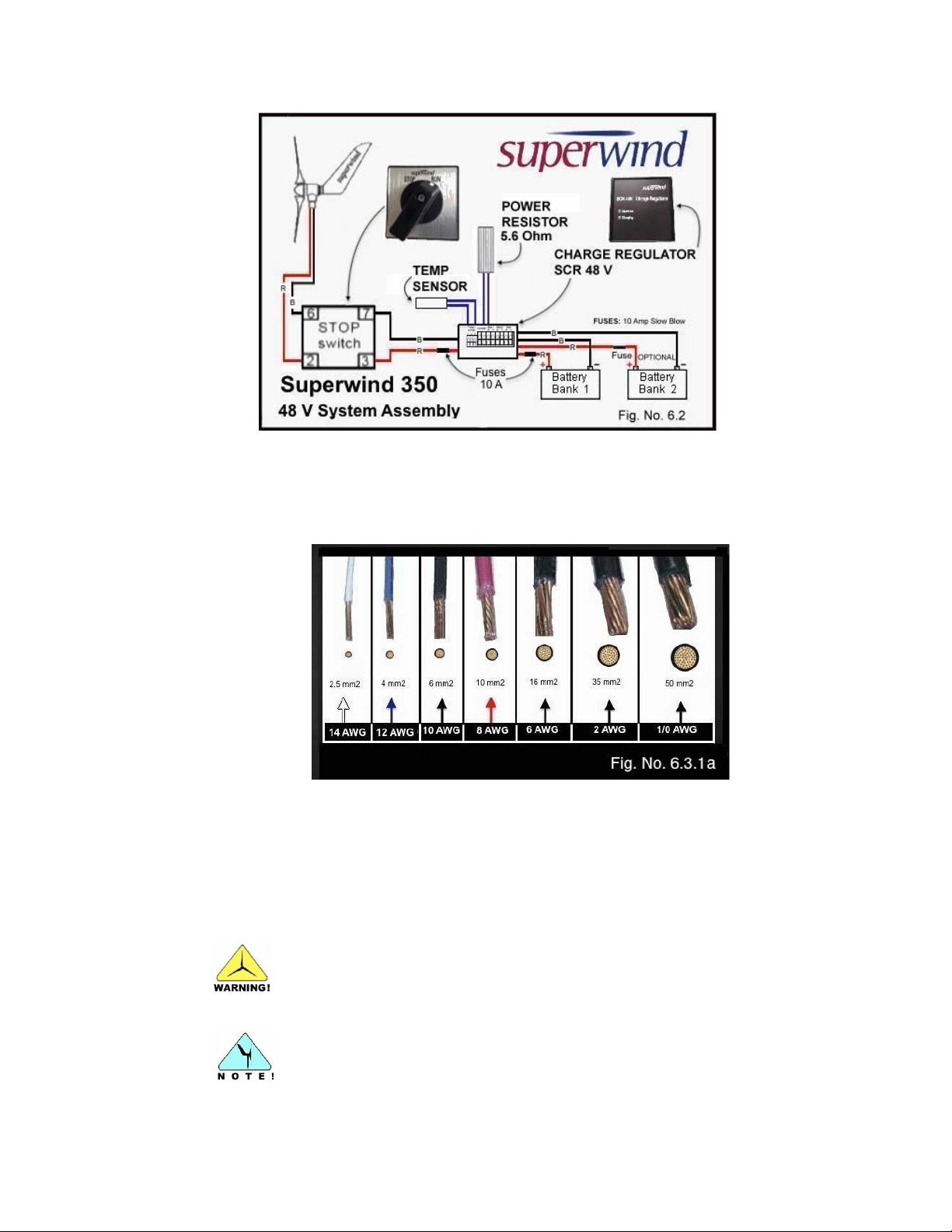
Figure 6.2 shows the wiring diagram for a typical Superwind 350/48V system.
© Copyright Mission Critical Energy Inc, 2019 Version 1-2019
www.superwind.com
Page 17
16
Cables with insufficient cross sections can heat up and cause a fire!
All values given in the tables below are based on a voltage drop of 3%.
6.3 System components
6.3.1 Wires
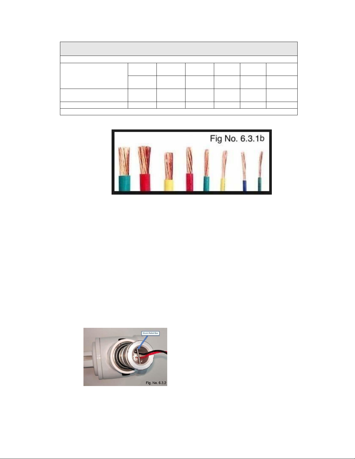
The cross section (also known as diameter or gauge) of the wires to be used will
depend on the length of the wire run and the rated voltage of your wind generator.
After deciding on a location, measure the distance from the top of the mast to the
battery and select the minimum cross section required as provided in the table below.
In order to keep power loss to a minimum and maintain safety, never use wires with
under-sized cross sections.
© Copyright Mission Critical Energy Inc, 2019 Version 1-2019
www.superwind.com
Page 18
17
AWG Wire Size Chart for Superwind 350/48V
Table No. 6.3.1
Distance from mast top to the battery
From:
To:
up to
19.8 m
19.9 m
31.7 m
31.8 m
47.6 m
47.7 m
79.3 m
79.4 m
126.8 m
126.9 m
198.2 m
Up to
64 ft
65 ft
104 ft
105 ft
156 ft
157 ft
260 ft
261 ft
416 ft
417 ft
650 ft
Minimum gauge
(cross section)
2.5 mm²
4 mm²
6 mm²
10 mm²
16 mm²
25 mm²
Recommended per wire
AWG 14
AWG 12
AWG 10
AWG 8
AWG 6
AWG 4
See Fig. No. 6.3.1b
The use of multi-strand, marine grade wire is recommended.
Solid wire is not recommended!
Tinned multi-strand, marine grade wiring is recommended for all marine insulations to
reduce corrosion issues.
For underground installations, the cable must be installed in conduit or be suitable for
direct bury applications. All cables and materials (heat shrink, insulating tape, etc)
should be ultraviolet resistant.
Chafe protection should be provided for the entire cable run. All penetrations into the
mast, electronics enclosures, etc, should be de-burred and the cable protected against
chafe using rubber sleeves, grommets, etc.
All wire terminations and connections must be made using suitable (preferably marine
grade) crimp on connectors.
6.3.2 Strain Relief
Depending on mast length and cable cross section,
the weight of the cable inside the mast can be
considerable. If the cable weighs more than 5 kg
(11 lbs) strain relief must be provided inside the
mast to prevent damage to the internal connection
point of your Superwind 350/48V (Fig. No. 6.3.2)
© Copyright Mission Critical Energy Inc, 2019 Version 1-2019
www.superwind.com
Page 19
18
The internal electronic rectifier of the Superwind 350/48V will be
destroyed by the application of reverse polarity anywhere within the
system.
Rectifiers damaged due to reverse polarity are not covered under
warranty!
6.3.3. Polarity
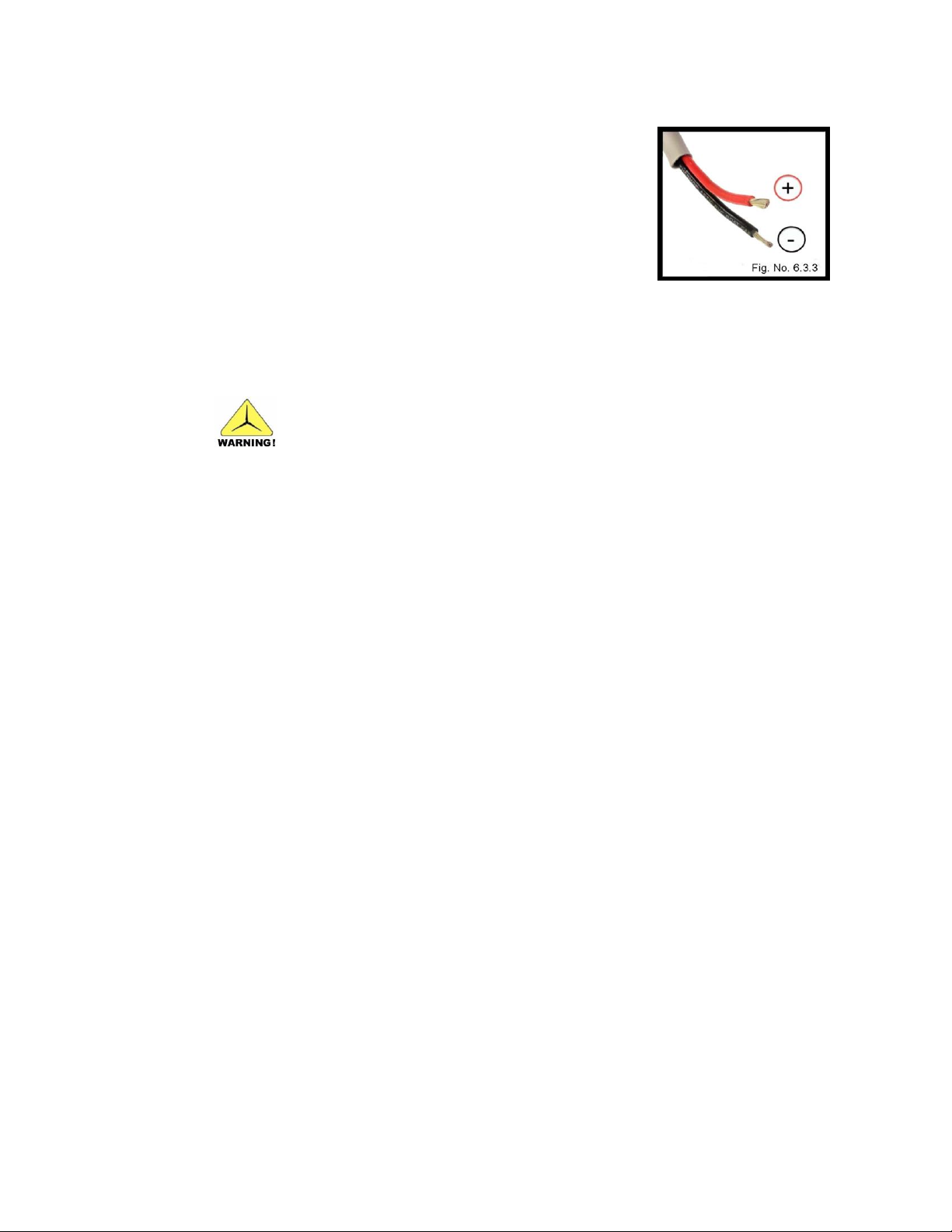
Always pay attention to the correct polarity of the wires.
Reversing polarity at the battery connections or anywhere in
the system will destroy the electronic rectifier of your
Superwind 350/48V. During installation or when changing
out batteries, clearly mark all wire ends as POSITIVE (+) or
NEGATIVE (-) to prevent connection errors. Fig. No. 6.3.3.
Marking of the connecting wires at the Superwind 350/48V:
POSITIVE Line (+) RED
NEGATIVE Line (-) BLACK
6.3.4 Batteries
6.3.4.1 Charging the batteries
The Superwind 350/48V is primarily used to charge batteries. For
proper battery protection, installation of the provided Superwind SCR 48V
Charge regulator and diversion load power resistor is mandatory.
The SCR 48V Charge Regulator allows the Superwind 350/48V to
operate automatically and completely unsupervised. The SCR 48V
Charge Regulator is suitable for use with all battery types and its use
ensures batteries are charged optimally and protected against overcharging
and damage.
6.3.4.2 Selecting the batteries
When selecting batteries, always ensure their voltage matches the rated
voltage of the system (48 volts in this case). The rated voltage of your
Superwind is specified on the data label located on the yaw shaft.
Flooded lead-acid batteries are the most commonly used battery type worldwide. They work well in a wide variety of applications and are very cost
effective, however they require periodic maintenance (electrolyte level checks,
etc).
The use of AGM (Absorbent Glass Matt) batteries has many advantages.
AGM batteries are sealed, virtually maintenance free, have a long service life
and can better survive the occasional deep discharge.
All batteries should be ‘deep cycle’ rated. Automobile type ‘starting batteries’
are not suitable for use as storage batteries and will fail rapidly due to the
cyclic operations associated with renewable energy-based charging.
© Copyright Mission Critical Energy Inc, 2019 Version 1-2019
www.superwind.com
Page 20
19
Never install batteries in a location where the danger of spark
formation exists. Ensure battery installations are provided adequate
ventilation at all times.
Never short-circuit the battery or terminals across a bank of
batteries!
Connect cabling to battery terminals only after all work on the
electrical system has been completed.
Use caution when conducting battery maintenance.
Wear protective clothing and suitable eye protection.
6.3.4.2.1 Battery Capacity
Another important factor of battery selection is capacity, which is expressed in
amp hours (Ah). This value represents the quantity of energy a battery can
store. The required battery capacity depends on individual site requirements
and factors such as location, wind availability, power consumption, power
generating systems, etc. Consult your battery supplier for assistance with
questions regarding load support, battery selection and installation.
Follow all manufacturer recommendations when selecting a location for your
battery installation. Charging flooded lead-acid batteries generates flammable
and potentially explosive hydrogen gas. Unsealed lead-acid batteries have
vent caps to release this gas, which can detonate if it is mixed with air and a
spark is present (from an electrical switch for example) or other ignition source
(open hot exhaust).
Batteries store a large quantity of energy, which can be suddenly discharged
in the event a battery is accidentally shorted. This sudden discharge can
destroy the battery (resulting in the release of battery acid and gas) and even
set the battery and cabling on fire. To protect against accidental shortcircuiting, do not attach battery terminal connections until all work on the
electric system has been completed.
6.3.4.3 Protection
Fuses (or appropriate circuit breakers) must be installed in the positive (+)
wires to the battery to protect the system against excessive current and/or
short-circuits. For fuse installation requirements, refer to the wiring diagrams
provided in Section 6.2 and Section 6.3.5.5. As a fuse can cause an electrical
spark when failing (blowing) do not install fuse holders in the same area as
the battery or bank.
Use caution when handling battery acid, adding distilled water or performing
other battery maintenance. Follow all battery manufacturer instructions and
wear protective clothing and suitable eye protection.
© Copyright Mission Critical Energy Inc, 2019 Version 1-2019
www.superwind.com
Page 21
20
6.3.5 Charge regulator SCR 48 V
6.3.5.1 Technical data
Nominal voltage ............................................................................. 48 V
Max. Charging voltage (25°C)........................................................ 57.6 V
Temperature compensation ........................................................... 144 mV/°C
Max. Current .................................................................................. 10 A
Resistance of dump resistor .......................................................... 5.6 Ohm
Number of charging outputs ........................................................... 2
Method of voltage regulation .......................................................... PWM
Connecting terminals ..................................................................... 4mm²
AWG12
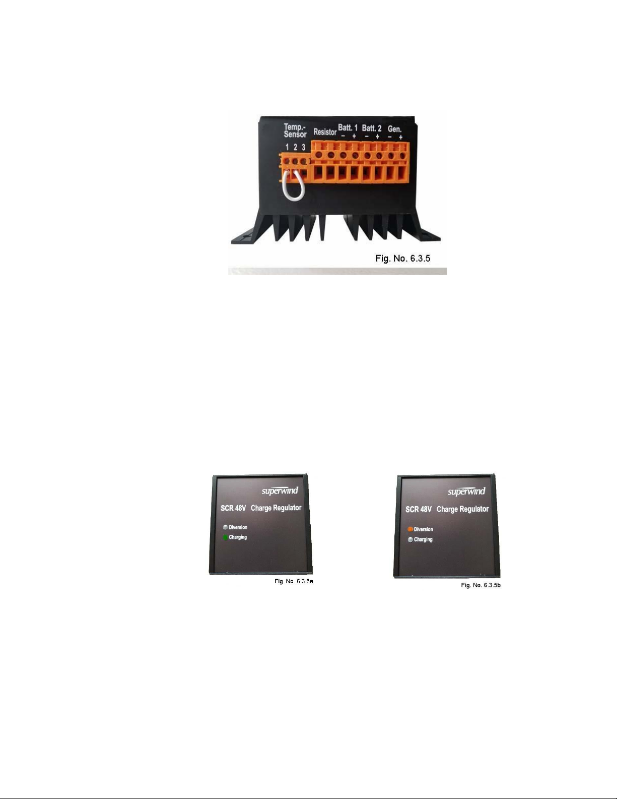
The illuminated GREEN “Charging” LED as shown in Fig No. 6.3.5a indicates
charge current is being sent to the battery.
The illuminated ORANGE “Diversion” LED as shown in Fig No. 6.3.5b
indicates the PWM circuit is limiting the charge voltage sent to the battery by
diverting excess power to the power resistor.
The default diversion set point level for the maximum charging voltage can be
adjusted as required to meet customer requirements. As special equipment is
required for proper calibration, this adjustment can only be performed by the
manufacturer or a Superwind authorized service partner.
© Copyright Mission Critical Energy Inc, 2019 Version 1-2019
www.superwind.com
Page 22

21
6.3.5.2 Functional description
The SCR 48 V charge regulator provided with your system has been
specifically designed for use with the Superwind 350/48V wind generator and
guarantees optimum charging of the batteries. As long as the actual charge
voltage is below the maximum charge voltage level, the current from the wind
turbine is routed directly to the battery or bank. Charge current flow to the
battery is indicated by an illuminated GREEN “Charging” LED (Fig. No.
6.3.5.a).
Once the battery or bank has reached maximum charge voltage, the PWM
circuit diverts the wind turbine’s surplus power to the diversion load power
resistor in order to keep the voltage constant. This state of charge is indicated
by an illuminated ORANGE “Diversion” LED (Fig. No. 6.3.5.b).
When the batteries are fully charged, the wind turbine continues operating
(electrically loaded by the power resistor) and is ready to provide useable
power as soon as the maximum battery charge voltage level drops.
6.3.5.3 Installation Location
The SCR 48 V charge regulator is designed for indoor use and must be
mounted in a location where it is well protected from the elements. The charge
regulator’s temperature sensor has a cable length of 400 cm [157”] and
should be mounted close to the batteries (see Section 6.3.9).
The distance between the charge regulator and the battery should be a
minimum of 30 cm [12”], but must not exceed 400 cm [157”].
The distance between the charge regulator and the diversion load power
resistor should not exceed 200 cm [78” approximately].
The diversion load power resistor is IP 54 rated and can be mounted outdoors
(e.g. outside a switch cabinet). Due to the heat produced while in use, the
power resistor must be adequately ventilated. Never mount the power resister
on a flammable surface or near flammable items, as the resistor will dissipate
all of the wind turbine’s power into heat once the battery is fully charged.
6.3.5.4 Connecting the Charge Regulator
Before connecting the charge regulator, secure the wind generator by turning
the safety switch to the STOP position or by shorting the two generator cables
together (see Section 7.1.1).
Mount the regulator and the power resistor to a dry, non-flammable surface.
The resistor may also be mounted outdoors in a vertical position with the
cable outlets at the bottom.
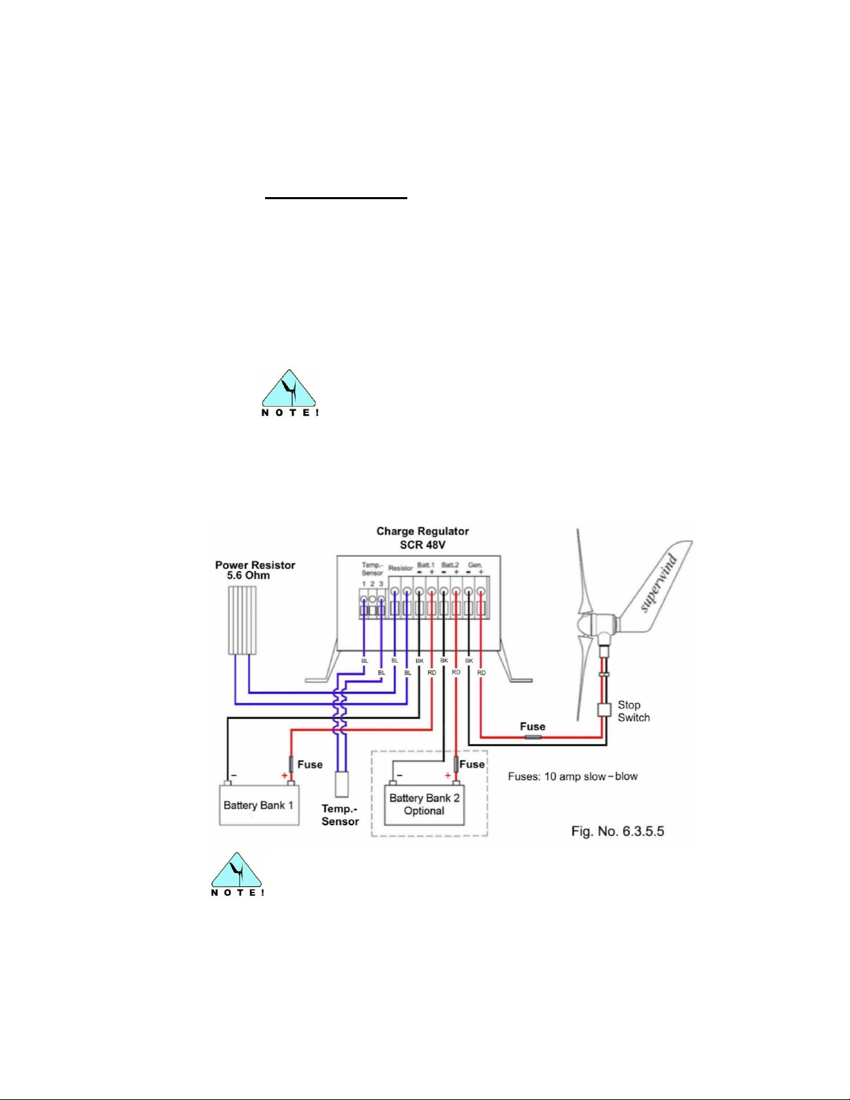
Connect the charge regulator per the wiring diagram as shown in Fig.
No. 6.3.5.5.
Use appropriate terminations for all wires connected to the charge regulator.
© Copyright Mission Critical Energy Inc, 2019 Version 1-2019
www.superwind.com
Page 23
22
To prevent damage to your system during installation, cables
must be connected in the following order:
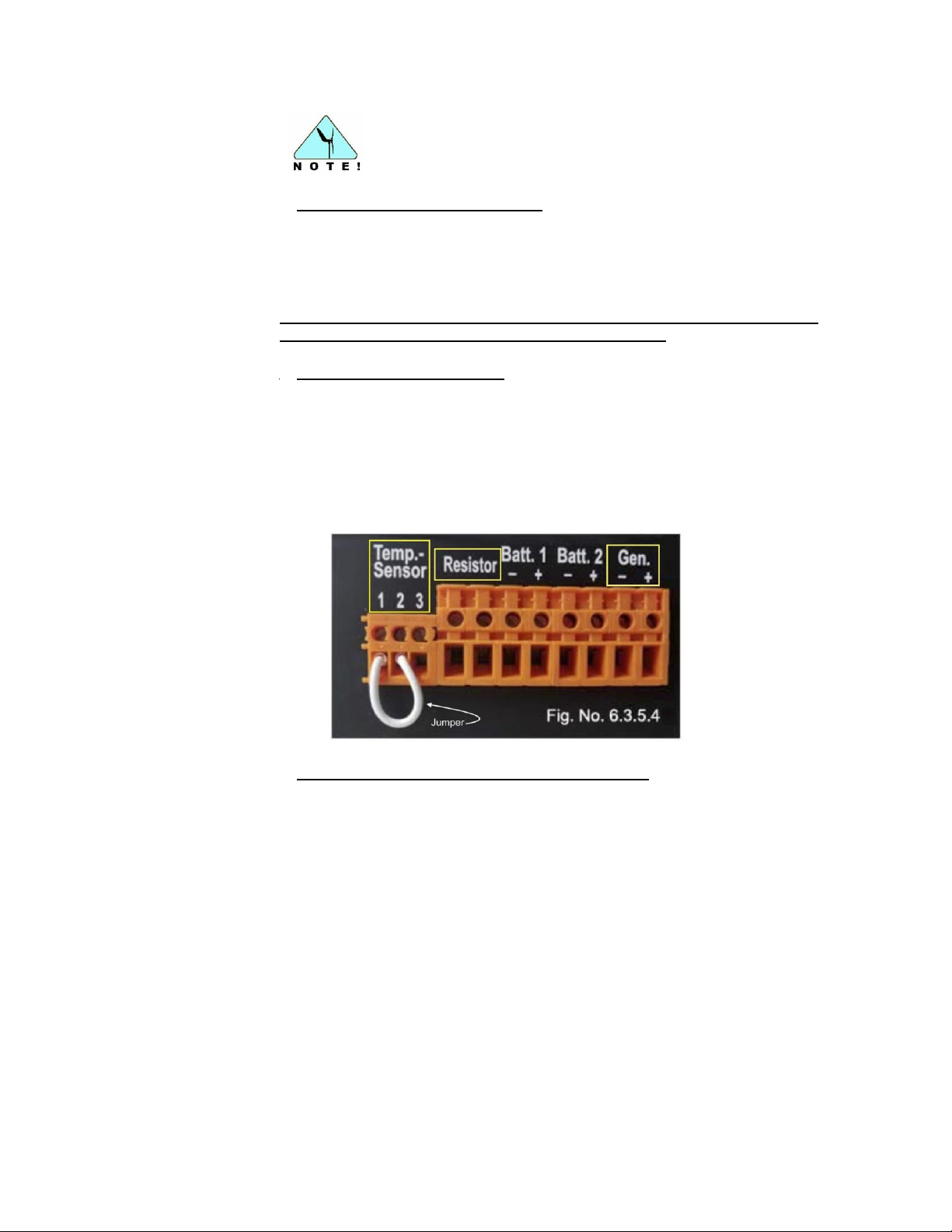
1. Connect the Temperature Sensor
Connect the two cables of the temperature sensor to terminals 1 and 3
Temp.-Sensor. If for any reason the temperature compensation function will
not be used, a jumper must be installed between terminals 1 and 2.
Note: The temperature sensor must be connected or the jumper installed
for the SCR 48 to function properly (Fig. No. 6.3.5.4).
2. Connect the Power Resistor
Connect both of the resistor wires to the terminals labelled Resistor (Fig. No.
6.3.5.4). The wires for the resistor are non-polarity specific, meaning the
connections at the charge regulator are interchangeable. Should the length of
the wires provided with the power resistor be insufficient, replace them with
new wires possessing a minimum cross section of 4 mm² (12 AWG) (refer to
Section 6.3.1).
3. Connect the Superwind 350/48V wind generator
Connect the wind generator to the charge regulator terminals labelled - Gen.
and + Gen. DO NOT reverse the polarity of these wires. Reversing the
polarity of the wires will destroy the charge regulator and void the
warranty. As a precaution, label the wire ends POSITIVE (+) or NEGATIVE (-)
in order to prevent reverse polarity connection errors (Fig. No. 6.3.5.4).
Mark the connecting cables of the Superwind 350/48V as follows:
POSITIVE (+) .......................... RED
NEGATIVE (-) ......................... BLACK
If unsure about the polarity of the cables from the wind generator, you can
identify POSITIVE (+) and NEGATIVE (-) easily using a multi-meter.
Select DC (10 VDC range) on your multi-meter. Connect the multi-meter
positive lead (red) and negative lead (black) to the cables coming from the
wind turbine, then ask an assistant to turn the rotor of the wind turbine slowly
© Copyright Mission Critical Energy Inc, 2019 Version 1-2019
www.superwind.com
Page 24
23
Connect the cables to the charge regulator and then to the
battery to prevent short-circuiting the battery during
installation.
The above diagram for the power resistor refers to a system utilizing only
one Superwind 350/48V as the power source.
by hand clockwise. If the voltage shown is positive (+), then the meter’s
positive lead is connected to the POSITIVE (+) turbine cable. If the voltage
shown is negative (-), then the meter’s positive lead is connected to the
NEGATIVE (-) cable of the wind turbine.
4. Connect the batteries
One or two batteries (or battery banks) can be connected to the SCR 48 V.
Use the terminals Batt. 1 - and Batt. 1 + to connect your first battery (or bank)
and the terminals Batt. 2 - and Batt. 2 + to connect your second battery or
bank (see Fig. No. 6.3.5.4 and Fig. No. 6.3.5.5 Wiring Diagram).
If two batteries or banks are connected to the SCR 48 V, each is charged
independently and is isolated from the other (to prevent discharge should one
battery or bank fail or have low charge voltage).
6.3.5.5. Wiring diagrams
Figure 6.3.5.5A shows the wiring diagram for a Superwind 350/48V with SCR
48 V Charge Regulator.
© Copyright Mission Critical Energy Inc, 2019 Version 1-2019
www.superwind.com
Page 25
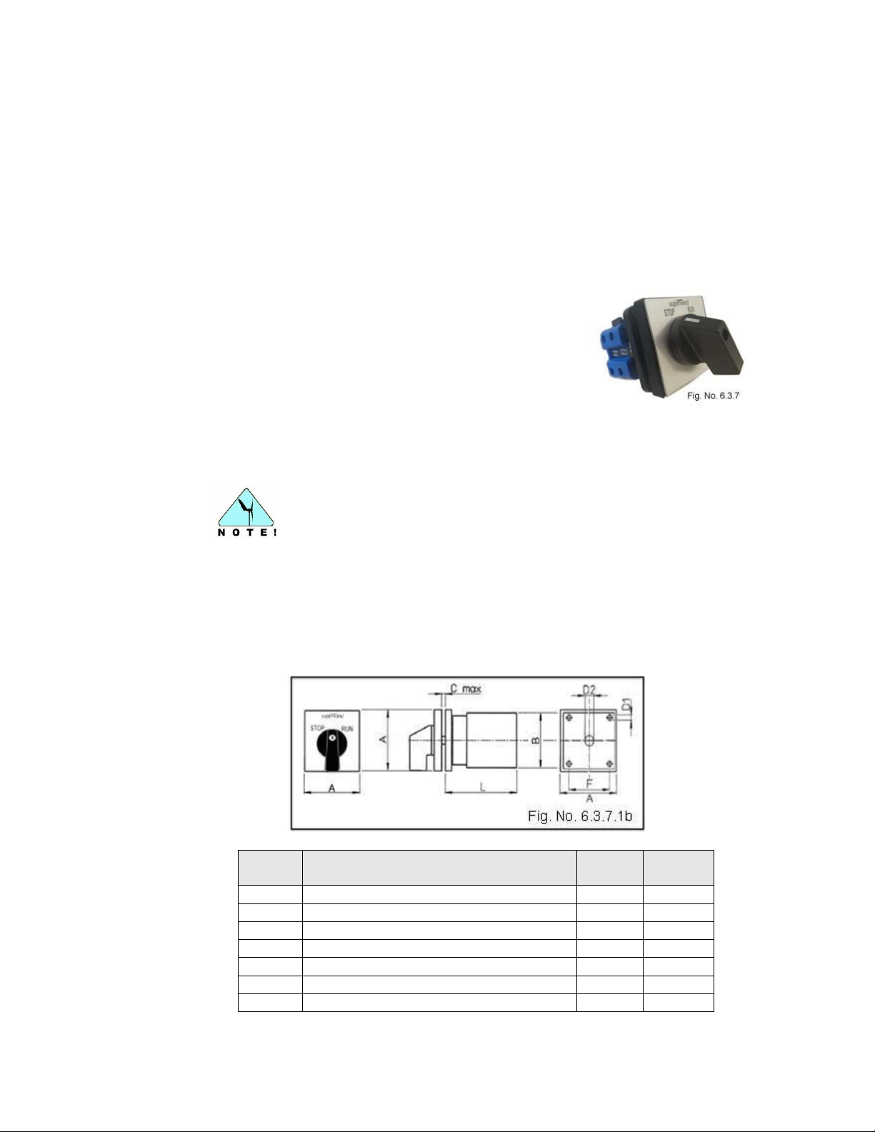
24
Installation of the provided Stop Switch is mandatory for safe
operation of your Superwind 350/48V.
Side
Dimensions
Table No. 6.3.7.2
mm
inches
A
FRONT VIEW: length & width
48
1.88”
B
REAR VIEW: length & width
42
1.65”
C
Panel Maximum Fitting Space
22
0.86”
D1
Screw fitting hole1 OD
4.1
1.61”
D2
OD Switch axle
20
0.78”
F
Screws fitting holes distance OC
36
1.41”
L
Inside cabinet
55
2.16”
6.3.6 Fuses
To protect the battery against short-circuits, fuses must be installed in the POSITIVE
line between the wind generator and the charge controller and in the POSITIVE line
between the charge regulator and the battery. These fuses must be 10 amp slow-blow
type or appropriate circuit breakers. See Fig. No. 6.3.5.5.
The fuses or breakers must be installed as close to the battery as possible, but not
within the same compartment, due to the possible generation of explosive hydrogen
gas while charging the batteries.
6.3.7 Stop Switch
The stop switch is used to shut down the wind generator
or to prevent starting of the rotor during maintenance,
repairs or when working in the turbine operational area.
In the STOP position, the switch connects the positive and
negative output wires of your Superwind 350/48V, short-circuiting its generator and
substantially reducing rotor speed. In the stop position, the switch also disconnects the
shorted generator from the battery circuit.
6.3.7.1 Mounting
The stop-switch is designed for indoor panel mounting only. The stop switch
shaft is adjustable to fit panels up to 7/8” (22 mm) thick. Fig. No. 6.3.7.1a.
6.3.7.2 Dimensions
© Copyright Mission Critical Energy Inc, 2019 Version 1-2019
www.superwind.com
Page 26
25
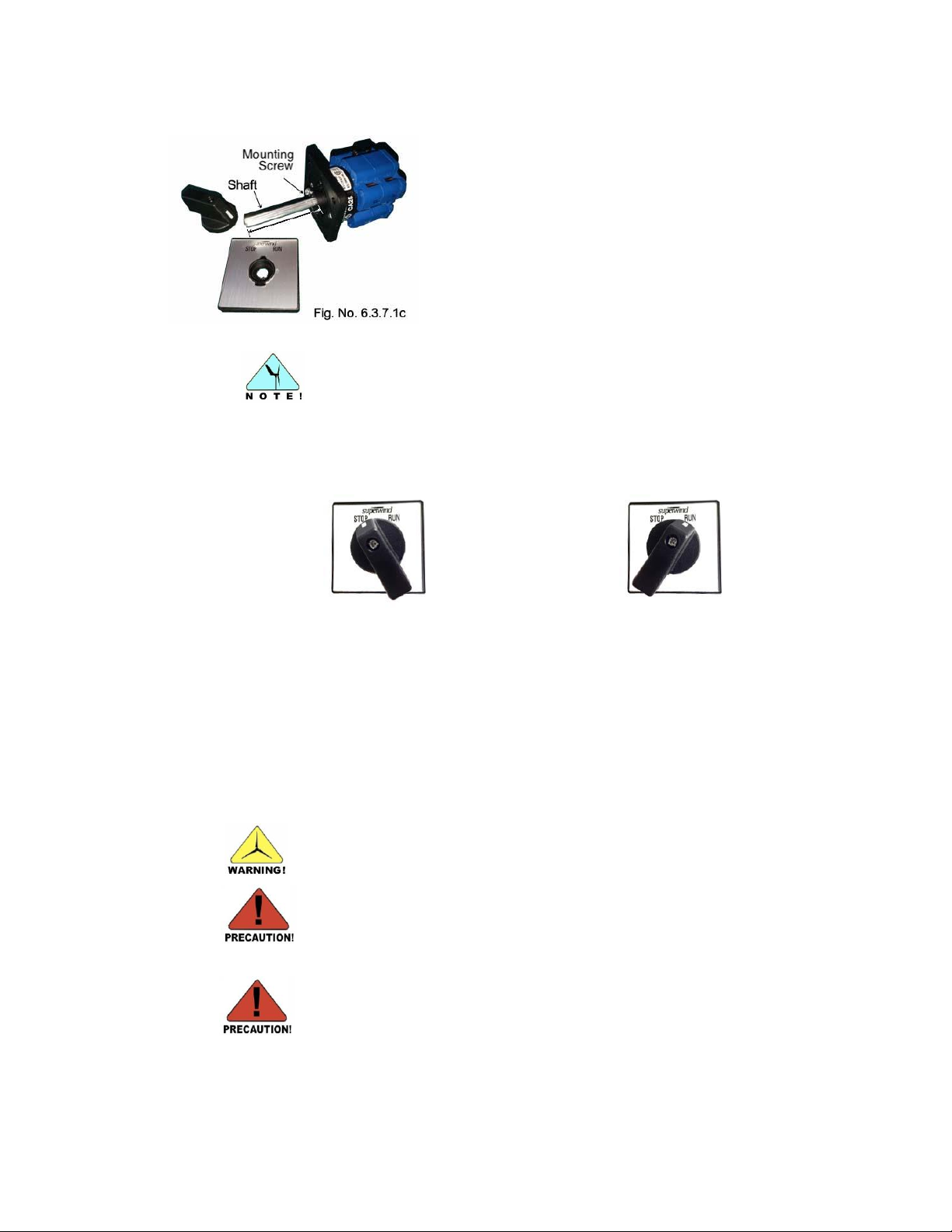
For very thin panels, it may be necessary to cut off the mounting
screw head afterwards for proper mounting.
STOP
RUN
The positive and the negative wires from
the wind generator are short-circuited
(generator short-circuit brakes the rotor).
The positive and the negative lines from
the battery or battery bank are open and
disconnected from the wind generator.
The positive and negative wires
from the wind generator are
connected to the battery or battery
bank via the SCR 48V charge
regulator.
All electrical work must be completed only by properly trained
technicians!
Disconnect all battery or battery bank terminals from the system prior to
making any system connections!
INSTALLATION OF THE INCLUDED STOP SWITCH AND SCR 48V
CHARGE REGULATOR IS MANDATORY!
IF THE CHARGE REGULATOR BECOMES INOPERATIVE, TURN
THE TURBINE OFF UNTIL THE CHARGE REGULATOR CAN BE
REPLACED.
DO NOT OPERATE THE SUPERWIND 350/48V WITHOUT AN
OPERATIONAL CHARGE REGULATOR INSTALLED!
Before installing the switch, adjust the shaft to the
length required and secure it by means of the mounting
screw (Fig No. 6.3.7.1c).
6.3.7.3 Electrical Connection
The stop switch has two positions:
© Copyright Mission Critical Energy Inc, 2019 Version 1-2019
www.superwind.com
Page 27
26
Installation of 10 amp slow-blow fuses in the positive (+) wire
between the stop switch and SCR 48V and the positive (+) wire
between the SCR 48V and the battery is mandatory!
Never install a circuit breaker or fuse between the stop switch and
the Superwind generator!
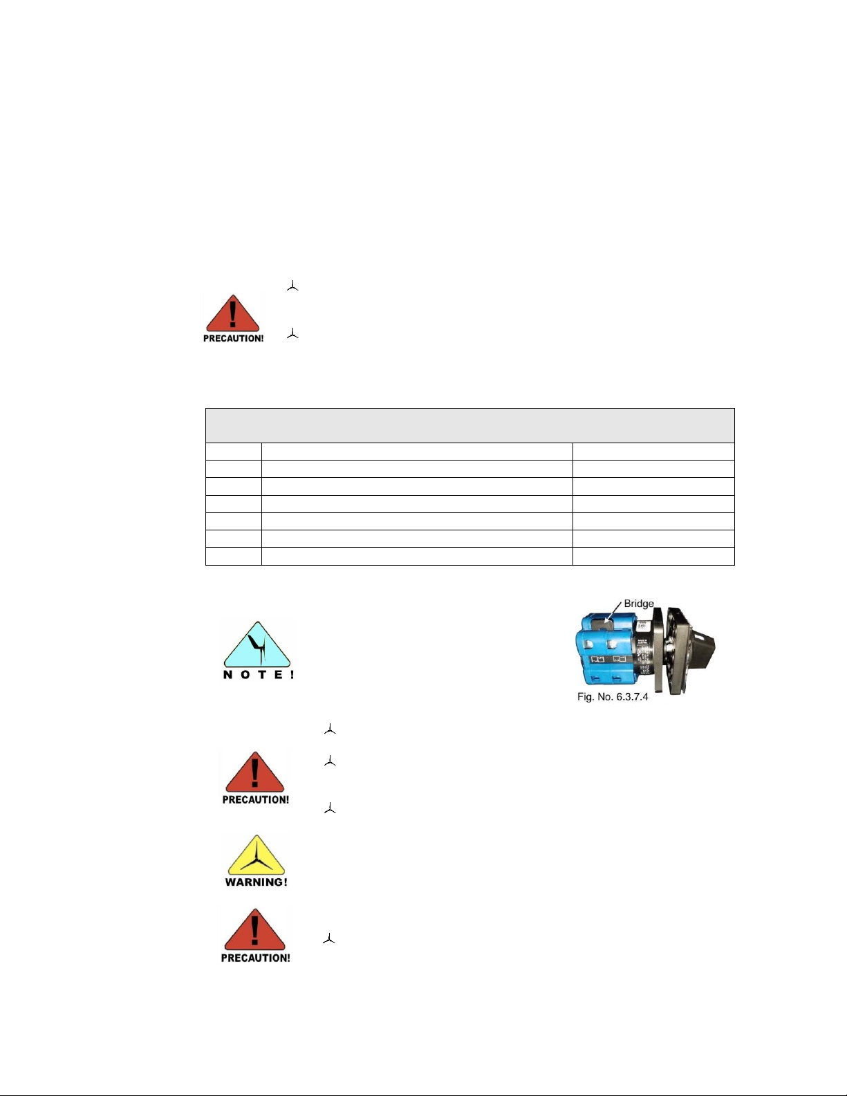
SWITCH TERMINALS
Table 6.3.7.4
Line
Description
Terminal Number
1
Superwind generator (+) Positive
2
2
Superwind generator (-) Negative
6
3
Charge regulator input (+)
3
4
Charge regulator input (-)
7
5
No connection allowed
4
6
No connection allowed
8
Do not remove the bridge
connecting terminals 1 and 5! The
stop switch will not operate
properly without it!
There are 8 wiring posts on the stop-switch. Only those
described in Table 6.3.7.4 should be used.
Ensure all terminal screws are properly tightened. If terminal
screws are loose (even those for terminals not in use) your
Superwind unit may not perform correctly.
Check the tightness of all stop switch terminal screws as part
of your annual Superwind inspection.
NEVER INSTALL A CIRCUIT BREAKER OR FUSE BETWEEN
THE STOP SWITCH AND THE WIND TURBINE.
Never install a non-Superwind stop switch!
Never substitute or install a non-Superwind stop switch. The Superwind stop
switch is specifically designed to disconnect the Superwind 350/48V from the
battery while simultaneously shorting the turbine leads, shutting down the
rotor. The stop switch must be installed in line between the wind generator
and the SCR 48V, as close to the wind generator as possible (see Fig.
6.3.7.5).
The wires between the Superwind generator and the stop switch must be kept
as short as possible. For appropriate conductor cross-section refer to section
6.3.1.
6.3.7.4 SWITCH TERMINALS
© Copyright Mission Critical Energy Inc, 2019 Version 1-2019
www.superwind.com
Page 28
27
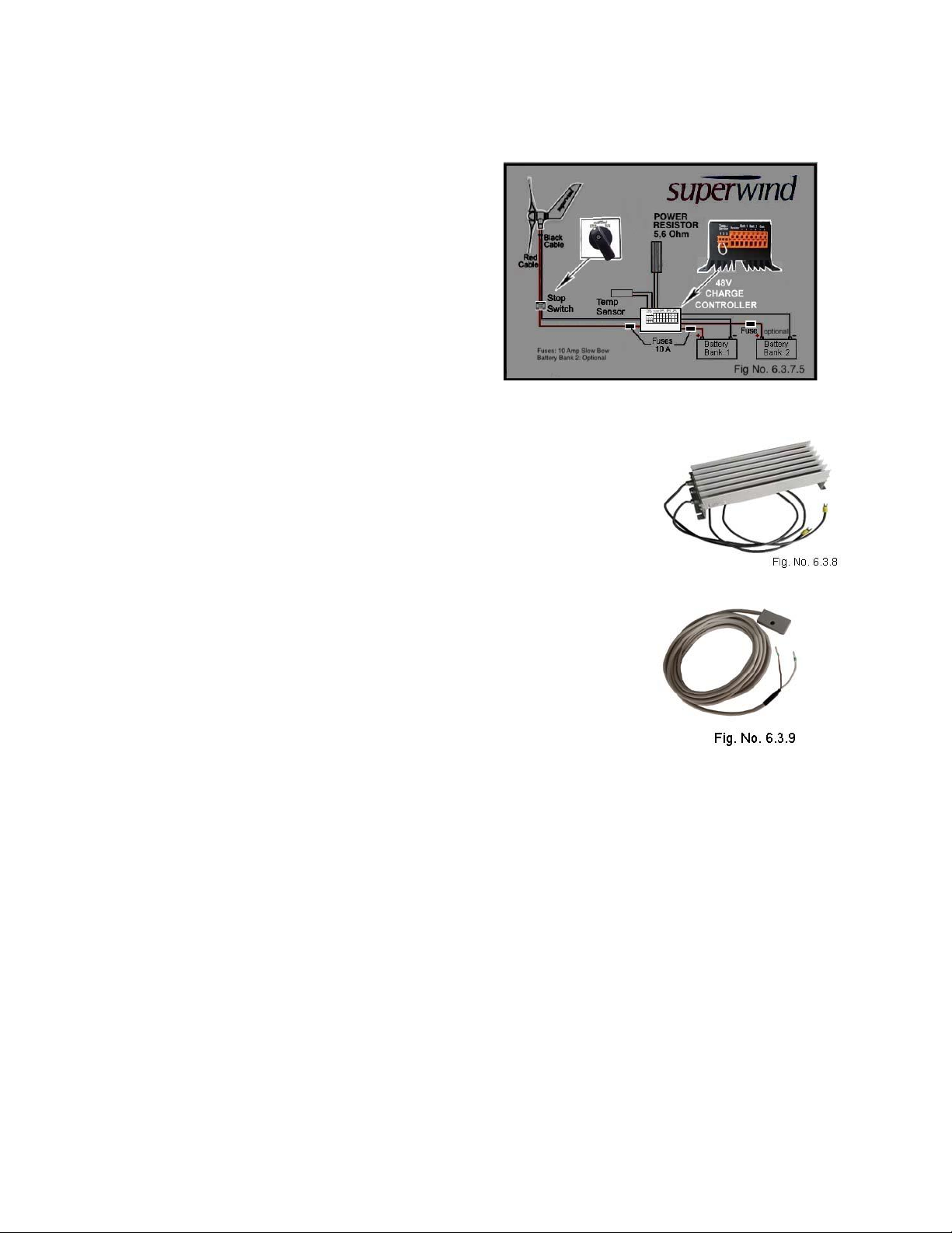
6.3.7.5 Component locations
The SCR 48V Charge
Controller is installed
between the battery bank and
the wind turbine. The Stop
Switch is installed between
the Superwind 350/48V and
the charge controller. The
required 10 Amp slow-blow
fuses are installed before and
after the SCR 48V Charge
Controller as shown in Fig.
No. 6.3.7.5
6.3.8 Diversion Load Power Resistor
The resistance of the wires connecting the power resistor to
the charge regulator can affect the charging voltage. As
such, the length of the wires connecting the power resistor
should not exceed the provided 1 meter (3 feet). If it is
necessary to extend the resistor wires run beyond 1 meter,
please refer to the AWG Wire Size Chart (Table No. 6.3.1
and Figs. 6.3.1a and 6.3.1b).
6.3.9 Temperature Sensor
The remote temperature sensor is a 6.4 meter (25’) long
cabled sensor designed to provide battery temperature
compensation charging from the SCR 48V charge regulator.
The sensor cable wires are non-polarity specific, meaning
the two plug connections at the charge regulator are
interchangeable.
6.4 Grounding
Your Superwind should be properly grounded to protect the system against damage
due to lightning, over voltage, etc. Grounding system design depends on factors such
as local conditions, place of installation, type of soil, depth of groundwater table or the
availability of a pre-existing grounding bus. Consult a competent electrician or
electrical system technician should questions exist concerning the design or
installation of the grounding system.
© Copyright Mission Critical Energy Inc, 2019 Version 1-2019
www.superwind.com
Page 29
28
7.
SUPERWIND 350/48V GENERATOR ASSEMBLY
Conduct work on the mast or wind generator on a calm,
windless day
Do not step or allow others to stand beneath hanging loads
(e.g. a tilted mast).
Disconnect all batteries from the system prior to conducting
any work.
Never approach a turning rotor – Stay away from moving
blades!
Never try to stop a turning rotor by hand.
Never secure the wind turbine by tying off a blade to the
mast. This will damage or distort the aerodynamic design
of the blade and affect the performance of the turbine.
Never install the wind generator in a location where persons
can accidentally come into contact with rotating blades.
DISCONNECT ALL BATTERIES OR BATTERY BANKS
BEFORE SHORT-CIRCUITING THE TWO GENERATOR
WIRES!
7.1 Precautions
Please read this manual in its entirety prior to installing your Superwind 350/48V and
note all recommended safety precautions to be followed during installation. Ensure the
mast and support structure is capable of safely handling the loads of your wind
generator. The mast not only has to withstand the weight of the wind generator and its
mass moment of inertia (i.e. when installed on a yacht) but also the thrust generated
by high wind speed. For example, the maximum wind thrust during normal operating
parameters will be approximately 70 N of force, however in an extreme gust (wind
speed of 49 m/s [95.24 Kn]) the thrust can rise up to 220 N!
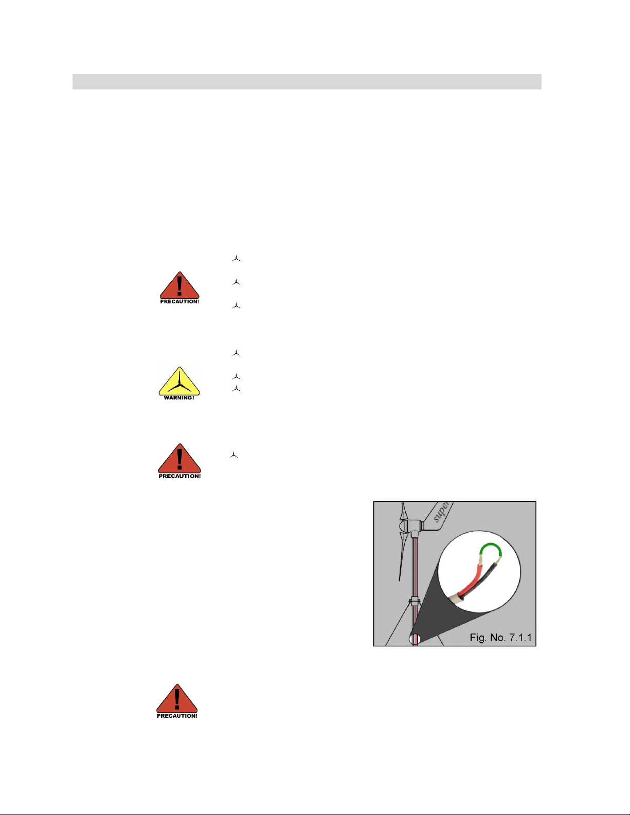
7.1.1 Short-Circuit
TO PREVENT THE GENERATOR FROM
STARTING UNINTENTIONALLY (PRIOR TO
INSTALLATION OF THE STOP SWITCH)
“SHORT-CIRCUIT” THE GENERATOR BY
CONNECTING THE TWO GENERATOR
WIRES TOGETHER AS SHOWN IN FIG.
7.1.1
© Copyright Mission Critical Energy Inc, 2019 Version 1-2019
www.superwind.com
Page 30
29
American
Delrin®
(White)
American
Stainless Steel
American
®
(Black)
7.2 DELRIN® BUSHINGS
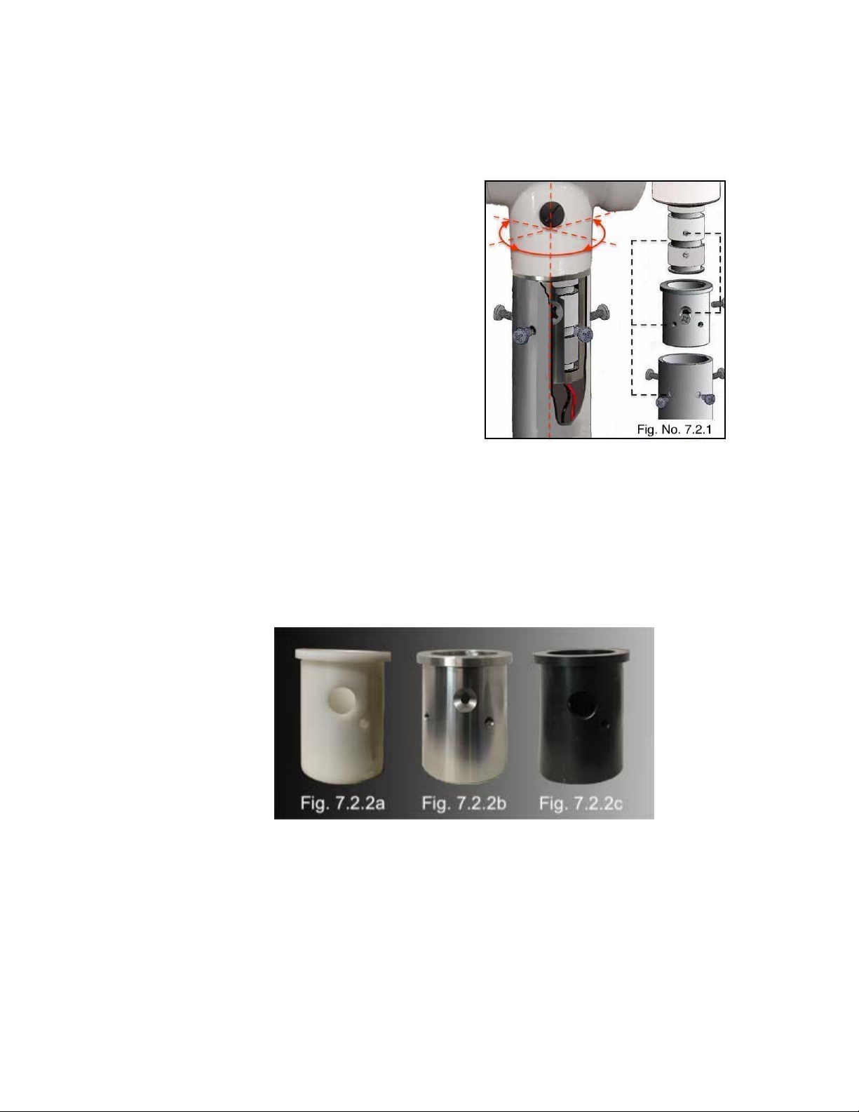
7.2.1 Bushing Basics
A bushing is the piece of equipment that
anchors the Superwind yaw shaft to the
mast, allowing it to freely rotate 360º on
its vertical axis. The bushing slides over
the yaw shaft of the turbine, where it is
then fastened in place utilizing three
screws. Once attached to the yaw shaft,
the bushing is then inserted into the mast
tube and screwed in place for support,
stability and safety (Fig. No. 7.2.1).
The original bushing used with the
Superwind 350 turbine was designed to
help with noise reduction when installed
aboard sailing yachts. The concept and
design of these bushings has evolved
considerably since then.
7.2.2 Bushings Types
There are currently three types of bushings available for use with the Superwind
350/48V allowing installations that can accommodate a wide variety of mast
configurations These are the American Delrin® (White), the American Stainless Steel,
and the American Delrin® (Black) bushings (Fig. 7.2.2a, 7.2.2b and 7.2.2c). Bushing
selection depends on the type of location the turbine will be deployed in.
American Delrin® bushings are used for integration on ships and other salt water
applications. The optional American Stainless Steel bushing is used on tall towers and
in locations subject to higher wind speeds, as well as mobile platforms (such as
trailers).
© Copyright Mission Critical Energy Inc, 2019 Version 1-2019
www.superwind.com
Page 31
30
The American Stainless Steel bushing is an option for use in
areas that experience extreme wind conditions. A detailed
description and installation instructions for this bushing are
provided with the unit.
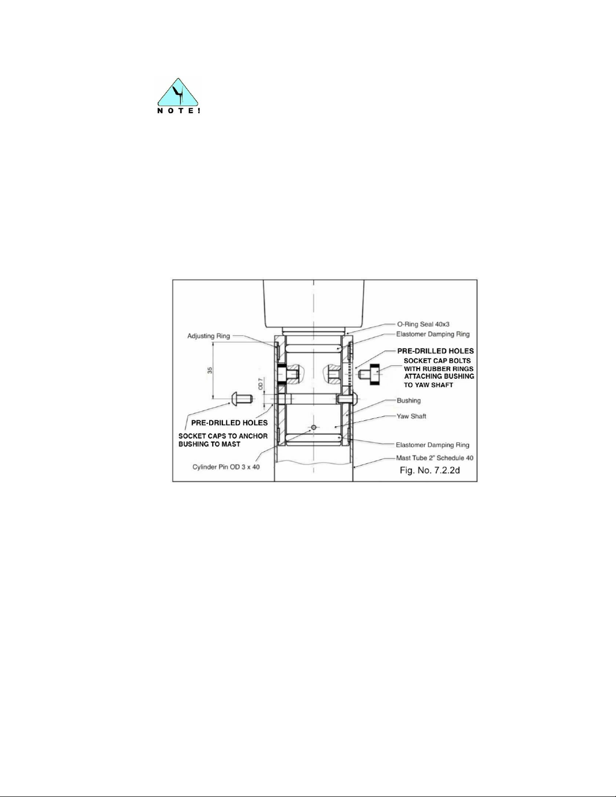
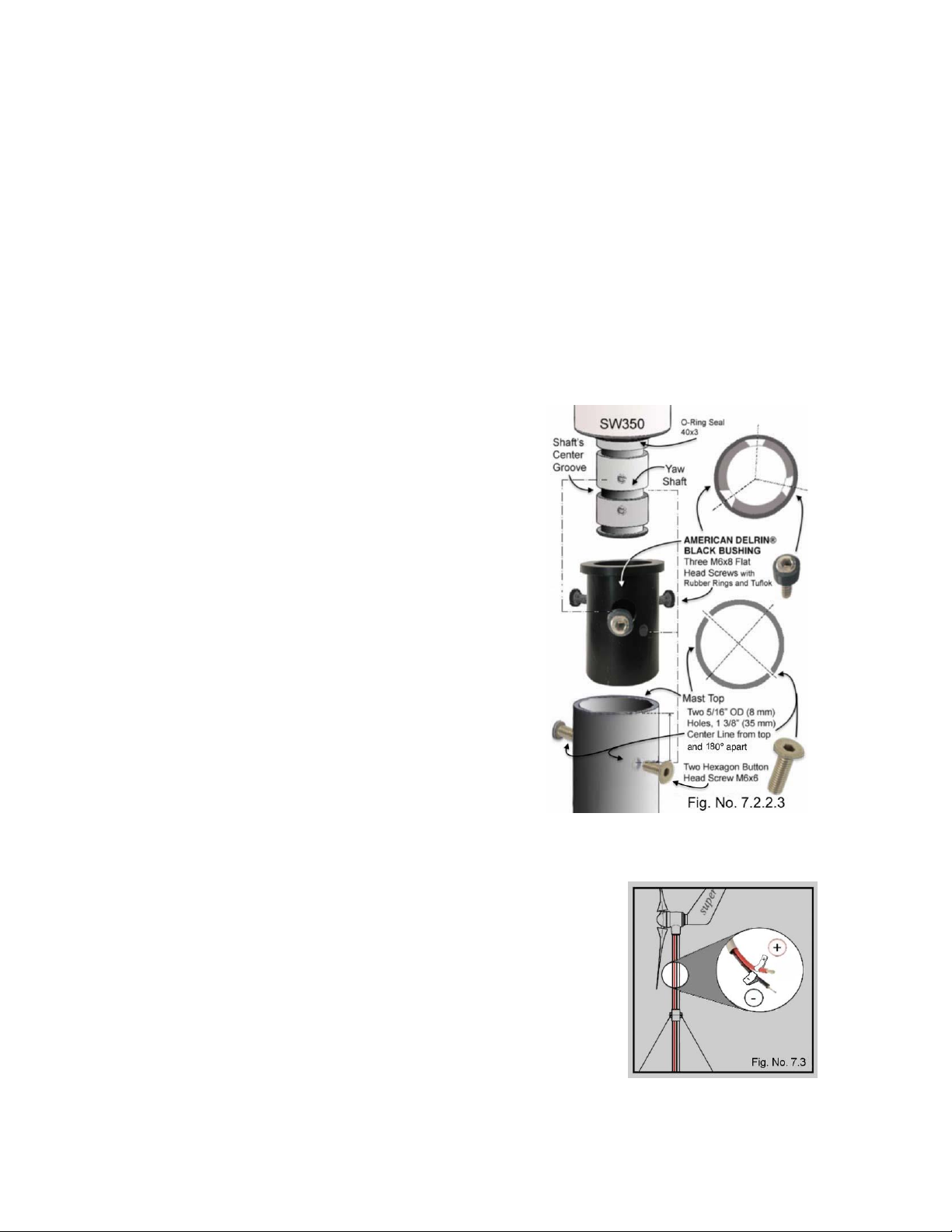
The American Delrin® (White) and the American Delrin® (Black) bushings come with
predrilled holes to facilitate attachment to the yaw shaft and to the mast with their
respective hardware as follows (Fig. No. 7.2.2d).
Three (3) M6 x 8 Socket cap screws (with TUFLOK coated threads and rubber
rings) are included and are used to attach the bushing to the yaw shaft.
Two (2) M6 x 6 hexagon socket button head screws (also included) are used
to attach the bushing to the mast. These screws will extend into the groove of
the yaw shaft, but will not touch it. Optional M6 x 12 screws are also included
and may need to be used, depending on installation requirements.
The default bushing for the Superwind 350/48V is either the 2.08 inch (52.832mm)
Delrin® White bushing or the 2.055 inch (52.197mm) Delrin® Black bushing,
depending on the customer’s specific needs (if a stainless or aluminum pipe mast is
being used for example).
© Copyright Mission Critical Energy Inc, 2019 Version 1-2019
www.superwind.com
Page 32
31
BUSHING QUICK GUIDE
Chart No. 7.2.2
Type of Bushing
Dampener
Rings
On/Off
Inner Hardware
Outer Hardware
American Delrin®
(White)
Fig. No. 7.2.2a
ON
(3) – Socket Cap
Screw
with rubber rings (M6
X 8)
(2) – Hexagon socket button
head screw (M6 x 6 or M6 x
12)
American
Stainless Steel
Fig. No. 7.2.2b
OFF
(3) – M6 x 14
(4) – Pan head ¼” 20 screw
(or alternative) with TUFLOK
American Delrin
®
(Black)
Fig. No. 7.2.2c
OFF
(3) – Socket Cap
Screw
with rubber rings (M6
X 8)
(2) – Hexagon socket button
head screw (M6 x 6 or M6 x
12)
BUSHING QUICK GUIDE
7.2.2.1 American Delrin® (White) Bushing
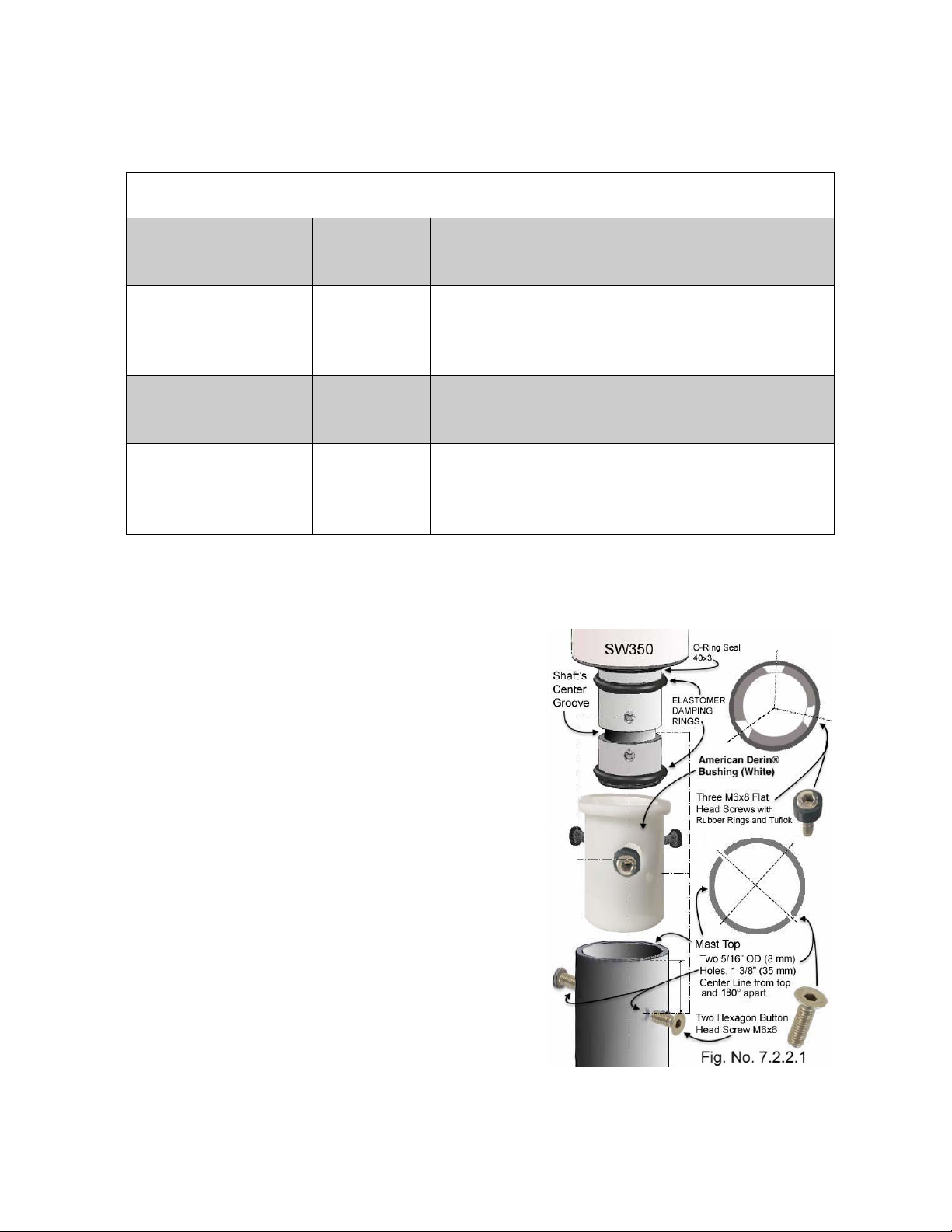
The Superwind 350/48V comes
with two (2) black elastodamphner
rings installed on the yaw shaft (Fig.
No. 7.2.2.1). When using the
American Delrin
both of the black elastodamphner
rings installed on the SW350/48V
must stay on the yaw shaft during
installation. Coating the elastodamphner rings and inside of the
bushing with Vaseline® (supplied)
prior to installation will lessen
resistance when inserting the yaw
shaft into the bushing. Delrin® will
swell slightly in salt water
applications. This can be useful in
helping to reduce any non-circular
dimensions of the mast. When
installed correctly, the bushing
provides both sound and vibration
dampening.
The inner diameter of the American
Delrin® (White) bushing is 44.2 mm
(1.74 inches). The maximum outer
®
(White) bushing,
© Copyright Mission Critical Energy Inc, 2019 Version 1-2019
www.superwind.com
Page 33
32
diameter of the bushing is 52.9 mm (2.08 inches). It is to be used with a 2”
schedule 40 stainless steel tubing mast.
When required, the outer diameter of the bushing can be reduced slightly by
sanding to help accommodate installation inside the mast.
Hardware provided in this kit includes three (3) M6 x 8 Socket cap screws with
TUFLOK coated threads and rubber rings used to attach the bushing to the
yaw shaft. Two (2) M6 x 6 hexagon socket button head screws are used to
attach the bushing to the mast (optional M6 x 12 hexagon socket button head
screws are also included). These screws will extend into the groove of the
yaw shaft, but should not touch it.
7.2.2.2 American Delrin® (Black)
The Superwind 350/48V comes
with two (2) black elastodamphner
rings installed on the yaw shaft.
When using the American Delrin®
(Black) bushing, both of the black
elastodamphner rings installed on
the SW350/48V must be removed
from the yaw shaft prior to
installation. The American Delrin®
(Black) will swell slightly in salt
water applications. This can be
useful in helping to reduce the noncircular dimensions of the mast. If
required, the outer diameter of the
bushing can be reduced slightly by
sanding help accommodate
installation inside the mast. The
inner diameter of a American
Delrin® (Black) bushing is 42.2 mm
(1.66 inches). The outer diameter of
an American Delrin® (Black)
bushing is 52.1 mm (2.05 inches).
Hardware included are three (3)
Socket cap screws with rubber rings (M6 x 8 with TUFLOK) and two (2)
hexagon socket button head screws (M6 x 6) or (M6 x 12).
7.3 Mast mounting
Before mounting the Superwind 350/48V on the mast
or support, the wiring from the generator to the stop
switch must be led through the mast tube (Fig. No. 7.3)
and be connected to the switch with correct polarity (see
Section 6.3.3).
© Copyright Mission Critical Energy Inc, 2019 Version 1-2019
www.superwind.com
Page 34
33
Mounting on a mast tube 60.0 mm or 60.3 mm
Chart No. 7.3.1.
Outer-OD *
Thickness
Inner-ID **
Material
60.3 mm
2.3 mm
55.7 mm
steel, welded
60.3 mm
2.0 mm
56.3 mm
stainless steel,
welded
60.0 mm
2.5 mm
55.0 mm
aluminum,
seamless
* OD: Outside Diameter
** ID: Inside Diameter
NOTE: The following applies to all mast and support structures:
Before assembling the wind generator, ensure there are no fittings, stays, etc, in the
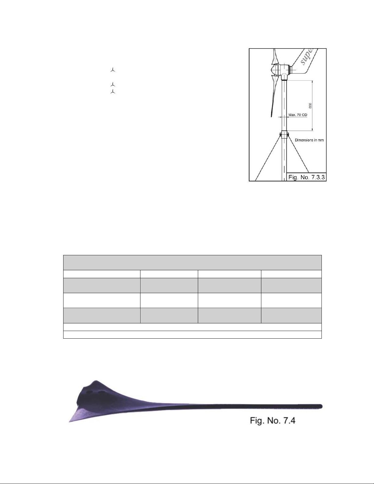
area from the top of the mast top to a point 650 mm below the mast top. This
clearance is crucial, because as the rotor controller pitches the blades at high wind
velocities, the distance between the blades and the mast will be reduced.
7.3.1 Mounting on a 60.3mm or 60.0mm mast tube
The yaw shaft of your Superwind 350/48V fits multiple sizes of mast tubes:
7.3.1.1 Preparations at the mast head:
Deburr the end of the tube carefully (inside and outside).
File off the welding seam if necessary.
With welded tubes, ensure the welding seam does not prevent insertion of the
yaw shaft. Smooth the seam with a round file or similar tool if necessary.
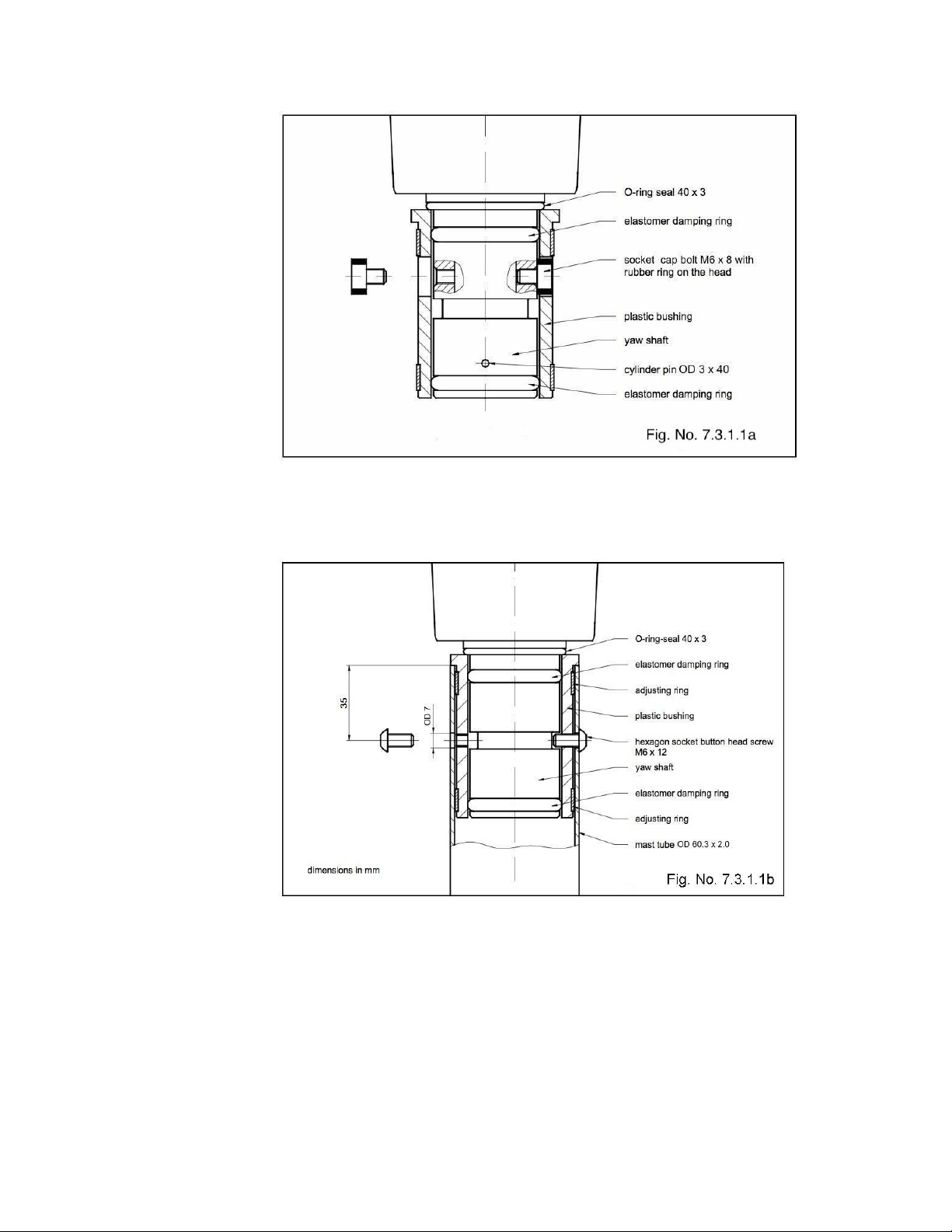
The included bushing (Delrin® White or Black) has to be mounted onto the
yaw shaft of the generator unit. Before installing the plastic bushing onto the
yaw shaft, align the three 16 mm OD holes of the bushing with the respective
threaded M6 holes of the yaw shaft. Then gently push the plastic bushing onto
the yaw shaft (with the collar facing the turbine) until reaching the stop limit
stop at the O-ring seal. In the case of the American Delrin® (White) bushing,
take care not to damage the damping rings during installation.
Next, insert the three rubber gasketed M6 x 8 socket cap bolts into each of
the holes and tighten until the heads are tight against the yaw shaft (Fig.
7.3.1.1a). Once installed correctly, the screw heads will be flush with the OD
of the bushing and will not interfere with insertion into the mast tube.
© Copyright Mission Critical Energy Inc, 2019 Version 1-2019
www.superwind.com
Page 35
34
Insert the yaw shaft of the Superwind 350/48V with the plastic bushing to the
limit stop (collar) and align the tapped holes with the drilled holes of the mast
(Fig. No. 7.3.1.1b).
Apply a small amount of Locktite® to the threads of the two hexagon socket
button head bolts (M6 x 12), insert and tighten for axial attachment. The bolts
now extend into (but do not touch) the groove of the yaw shaft.
© Copyright Mission Critical Energy Inc, 2019 Version 1-2019
www.superwind.com
Page 36
35
7.3.2 Mounting on a 48.3mm mast tube
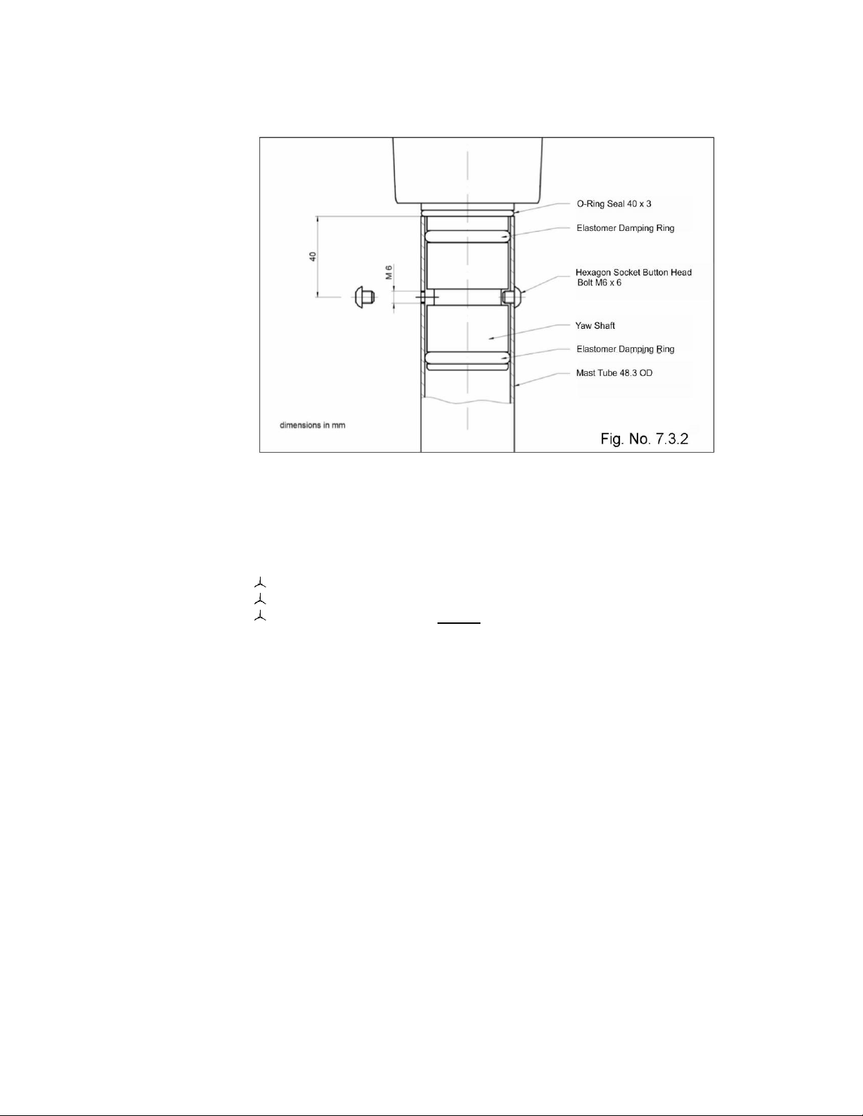
The Superwind 350/48V can also be mounted to a stainless steel 48.3 mm mast,
(Fig, 7.3.2) provided the wall thickness is 2.0 mm and the inner diameter is at least
44.0 mm.
7.3.2.1 Preparations at the mast head:
Deburr the end of the tube carefully (inside and outside)
File off the welding seam if necessary.
Drill two 5 mm holes and tap M6. The distance to the mast top is 40 mm.
With this configuration the plastic bushing and three rubber gasketed M6 x 8
socket cap screws are not needed. For easier assembly, lubricate the two
elastomer damping rings on the wind turbine yaw shaft and the inside of the
mast tube with Vaseline® or a similar petroleum jelly product. Now gently
push the yaw shaft into the mast until reaching the stop limit at the O-ring
seal, taking care not to damage the damping rings during installation.
Next, apply a small amount of Locktite® to the threads of the two hexagon
socket button head bolts (M6 x 6), insert and tighten for axial attachment. The
bolts will extend into the groove of the yaw shaft, but will not touch it. Once
assembled correctly, this installation provides both sound and vibration
dampening (Fig. No.7.3.2).
7.3.3 Mounting on other mast tubes
If other mast sizes are used to mount the Superwind 350/48V, ensure the inside
diameter is of the required size (to prevent excessive movement). The OUTSIDE
diameter of the tube must not be greater than 70 mm (2.75”) to ensure there is
sufficient space between the mast and rotor blades. There must also be no exterior
fittings, stays, etc, which could obstruct operation of the rotor (Fig. No. 7.3.3)
© Copyright Mission Critical Energy Inc, 2019 Version 1-2019
www.superwind.com
Page 37
36
Common American Masts
Chart No. 7.3.4
Mast Type
Inner Diameter*
Outer Diameter**
Wall Thickness**
Stainless Steel Pipe
(2” sch 40)
52.46 mm
2.065 in
60.3 mm
2.37 in
3.92 mm
0.15 inch
Stainless Steel Tube
(2 ¼”, 316L, 16 Gauge)
52.50 mm
2.066 in
57.15 mm
2.25 in
2.325 mm
0.09 inch
Aluminum Pipe
(2” sch 40)
52.50 mm
2.066 in
60.325 mm
2.375 in
3.912 mm
0.15 inch
*Inches are rounded to nearest thousandth
**Inches are rounded to nearest hundredth
7.3.3.1 Preparations at the mast head:
Deburr the end of the tube carefully (inside
and outside).
File off the welding seam if necessary.
Drill two holes at 7 mm.
Depending on the size of the tube, it is possible
that the two hexagon socket button head
screws provided for attachment (M6 x 12) may
be too short. Should this be the case, screws of
the appropriate length must be used. Ensure
that the replacement screws are of sufficient
length for the installation, but are not long
enough to touch the inner part of the yaw shaft.
Otherwise the sound and vibration dampening
ability of the installation will be compromised.
Apply a small amount of Locktite® to the
threads of the bolts prior to installation.
7.3.4 Mast Tube Specifications
The proper sizing for a mast selection is 2” schedule 40 stainless steel or aluminum
piping. Stainless steel tubing can be used as well, provided the size is 2 ¼”, 316L, 16
Gauge. However, any type of high quality, commercial grade metal can be used,
provided it is 2” schedule 40.
7.4 Rotor Blades
© Copyright Mission Critical Energy Inc, 2019 Version 1-2019
www.superwind.com
Page 38
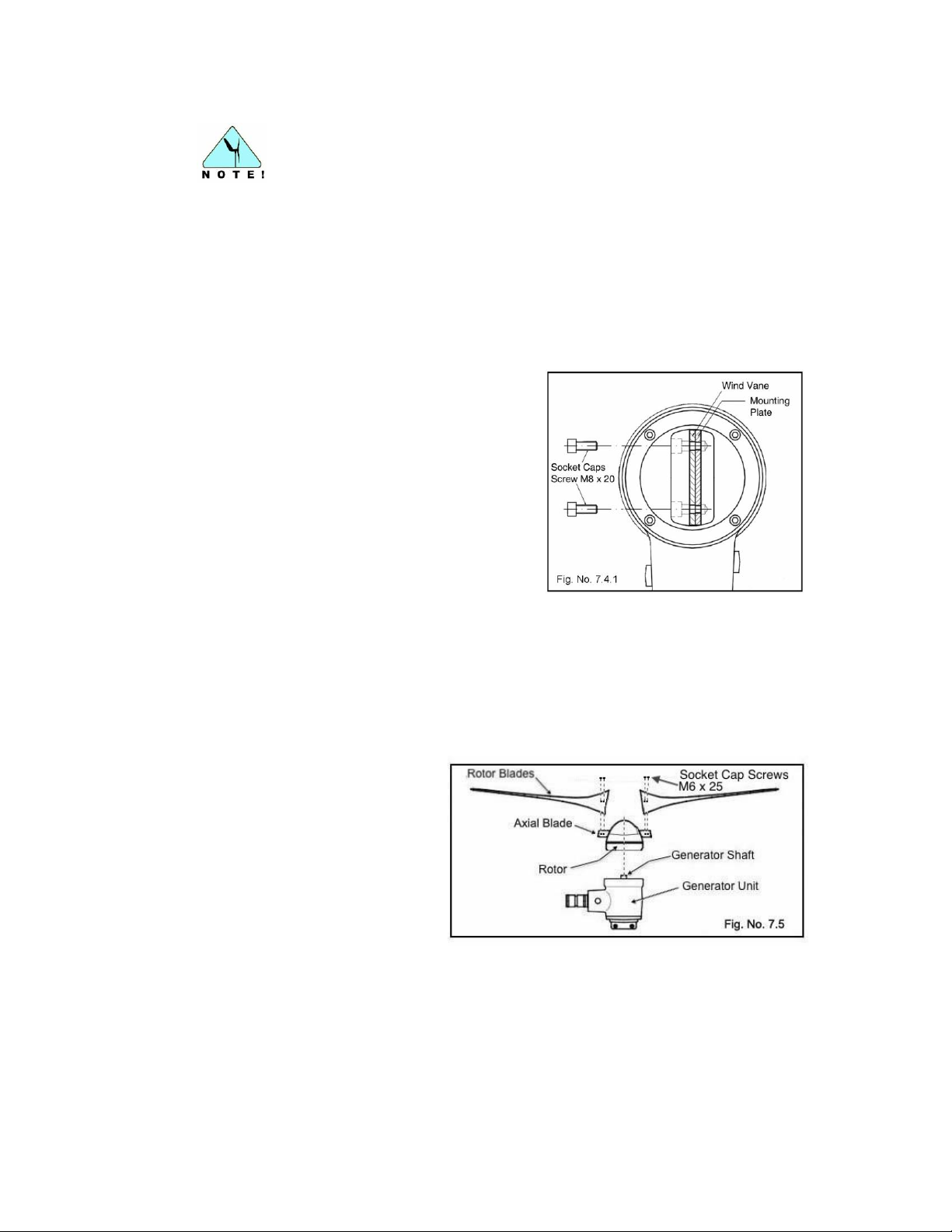
37
The trailing edges of the rotor blades are very thin and sharp. Exercise
caution when unpacking the blades to avoid injury. Fig. 7.4
Superwind rotor blades are manufactured as sets of three and are balanced by
weight and pitch deflection. The three blades can be fixed to the hub in any order,
however do not mix and match blades from different Superwind blade sets as this
could cause the rotor to become unbalanced. This means that if a single blade is
damaged, the entire set must be replaced.
7.4.1 Mounting of the wind vane
The wind vane is fastened to the rear cover
of the generator. Insert the wind vane and
the mounting plate into the groove. As
viewed from the rear (Fig. No. 7.4.1), the
mounting plate must be on the right side.
Next, insert the M8 x 20 socket cap screws
into the mounting plate and torque to 30nm
(22 ft lb). The screws have TUFLOK (blue
color) thread lock applied to prevent
loosening once installed and during
operation. Due to this coating, some
resistance during installation is normal.
Note: Check the tension of the socket cap screws M8 x 20 holding the mounting plate
and wind vane annually as part of the generator’s routine maintenance schedule.
7.5 Rotor assembly
There are two methods to that can be used to assemble the rotor of your Superwind:
a) The hub is mounted to
the generator shaft and
the rotor blades are
attached to the hub
afterwards.
b) The rotor blades are
attached to the hub first
and the assembled rotor
is then mounted to the
generator.
We recommend method “b” as it is easier in most cases to first assemble the rotor
completely at a convenient place, then mount the rotor to the generator.
© Copyright Mission Critical Energy Inc, 2019 Version 1-2019
www.superwind.com
Page 39
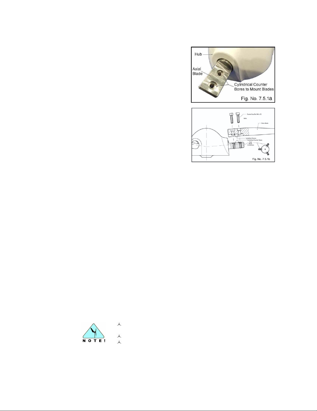
38
Ensure that the cylindrical tenons on each of the blades are
correctly inserted into the axle counter bores.
Do not use excessive force when installing the blades.
Do not over tighten the screws.
7.5.1 Attaching the rotor blades to the hub
Accurate positioning and mounting of the rotor
blades to the hub is ensured by their design,
which allows for one way installation only. The
flat portions of the axles sticking out (Fig. No.
7.5.1a) of the hub have two cylindrical counter
bores each. The rotor blades have rectangular
recesses with two cylindrical Tenon’s, which fit
into the cylindrical counter bores of the axle
when pressed with light force.
The rotor blades are attached by two M6 x 25
socket cap screws, the threads of which are
coated with TUFLOK to prevent loosening
during operation (Fig. No. 7.5.1.b). Due to this
coating, some resistance during installation is
normal.
To begin assembly of the rotor:
1. Place the hub with the flat side down on a soft surface with the three flat axles
horizontal and pointing upwards.
2. Attach the first rotor blade by aligning the cylindrical tenons of the blade to the
cylindrical counter bores of the axel and lightly pressing the blade into place. Use
caution, as the use of too much force can damage the threads.
3. Once both tenons are aligned correctly with the counter bores, screw in the two
socket cap screws M6 x 25 (Fig. No. 7.5.1b). Stainless steel threads are very soft,
so make sure the screws are first started by hand and not cross threaded. If
mounting the blade for the first time, it is recommended to insert the screws and
alternatively give each a half turn until the tenons are completely pressed into the
counter bores.
4. When the rotor blade is attached to the axle, do not simply tighten the screws, as
excessive force could damage the blade material. For the correct initial tension,
use a torque wrench to tighten the screws to a torque of 4.5 Nm. [3.31 lb/ft].
If a torque wrench is not available, the following method is recommended:
1. To ensure the contact surface on each blade face and adjoining axle fits properly,
insert both screws slowly, with offset pressure - one after the other - until snug.
Once properly positioned, increase the pressure slightly on each screw until it
starts to feel tight.
2. At this point, turn the screw exactly one quarter turn in order to adjust to the
correct final tension.
3. Continue mounting the other two blades the same way.
© Copyright Mission Critical Energy Inc, 2019 Version 1-2019
www.superwind.com
Page 40
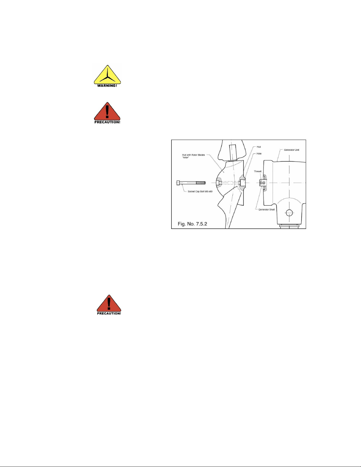
39
In order to prevent the rotor from turning unexpectedly during
installation, place the stop switch into the STOP position before
assembly of the hub to the generator shaft. Another option is to
disconnect the batteries, then short circuit the two generator cables.
DISCONNECT THE BATTERIES BEFORE SHORT CIRCUITING
THE TWO GENERATOR CABLES!
Do not push the generator shaft into the generator housing
during hub installation or damage to the generator will result.
This type of damage is not covered by the Superwind warranty!
7.5.2 Mounting the hub to the generator shaft
Once the rotor has been
assembled, hold the rotor by
the hub and center the hub
hole onto the generator shaft
(Fig. No. 7.5.2), paying close
attention to the alignment with
the generator shaft key. Avoid
holding or carrying the rotor
by the rotor blades. Doing so
will place unnecessary loads
on the blades and can cause
possible injury (as the edges
of the blades are sharp).
Gently slide the rotor onto the generator shaft, being careful not to push the generator
shaft into the housing of the generator unit. Next, insert the socket cap bolt M8 x 80
(Fig. No, 7.5.2) through the hub and tighten it until all axial play is removed. Torque
the socket cap bolt to 18 Nm. [13.27 lb/ft]. The socket cap hub bolt has TUFLOK (blue
color) thread lock applied to prevent loosening once installed and during operation.
Due to this coating, some resistance during installation is normal.
© Copyright Mission Critical Energy Inc, 2019 Version 1-2019
www.superwind.com
Page 41
40
8.
COMMISSIONING
done
Check List
Chart No. 8.1
Section:
Mast:
Assembled and erected in accordance to the respective manuals. Bolts, joints,
anchors and braces checked. Mast vertically adjusted.
7.3
Grounding / lightning protection:
Mast / support grounded.
6.4
Ground wire connected to the grounding bus.
6.4
Electrical system:
Batteries correctly installed and (if applicable) electrolyte at correct levels.
6.3.4
Charge Regulator SCR 48V correctly mounted and connected.
6.3.5
Power resistor correctly mounted and connected. Installation location provides
adequate heat dissipation.
6.3.8
10 amp fuse holders correctly installed and connected.
6.3.6
Stop switch correctly installed and connected.
6.3.7
Ammeter correctly installed and connected (optional).
Cabling in accordance with wiring diagram and correctly connected.
6.2
Polarity of all cables and connections verified as correct.
6.3.3
Wind Generator:
Cables connected with correct polarity.
6.3.3
Strain relief for cables provided (if necessary).
6.3.2
Yaw shaft correctly inserted into bushing and secured with screws.
7.2.
Wind vane correctly fastened with mounting plate screws tightened.
7.4.1
Rotor blades correctly fastened.
7.5
Rotor blade screws tightened at 4.5 Nm [3.32 lb/ft].
7.5.1
Hub mounted on the generator shaft and tightened at 18 Nm [13.27 lb/ft].
7.5.1
Before initial operation of your new Superwind 350/48V verify correct installation using the
check list below.
8.1 Check List
Once all installation work has been completed correctly and verified, install all fuses and place
the stop switch into the RUN-position. Your new Superwind 350/48V is now ready for
operation.
CONGRATULATIONS!
© Copyright Mission Critical Energy Inc, 2019 Version 1-2019
www.superwind.com
Page 42
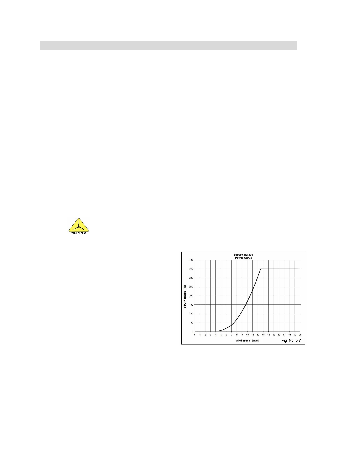
41
9.
OPERATION
Never try to stop a spinning rotor by hand. Even when slowed down by the stop
switch, a slowly running rotor can cause serious injuries.
9.1 Safety instructions
Do not operate the Superwind 350/48V until first verifying that personnel cannot
touch or come in contact with the rotor.
Do not operate the Superwind 350/48V unless it is properly connected to an electrical
load. Examples of improper operation include running the generator with no load
connected or when connected to a fully charged battery in a system without a charge
regulator and power resistor installed.
9.2 RUN and STOP
While the Superwind 350/48V is designed for autonomous, unattended operation in
all weather conditions, there will be situations where you would like to stop it (extreme
weather, maintenance, repairs, etc). As such, installation of the provided stop switch is
mandatory for all installations.
In the RUN-position the wind generator supplies power to the battery and consumers
connected. Placing the switch into the STOP-position simultaneously disconnects the
wind generator from the battery and short-circuits the generator leads, shutting down
the rotor. In very high wind conditions the rotor may continue to rotate, although at
very low revolutions.
9.3 Power control
As described earlier in Section 4.3b
the Superwind 350/48V is
equipped with a unique
aerodynamic feathering rotor
control system. This over speed
control helps ensure constant
electrical output at high wind
speeds, adding to the unit’s
autonomous operation and
safety.
© Copyright Mission Critical Energy Inc, 2019 Version 1-2019
www.superwind.com
Page 43
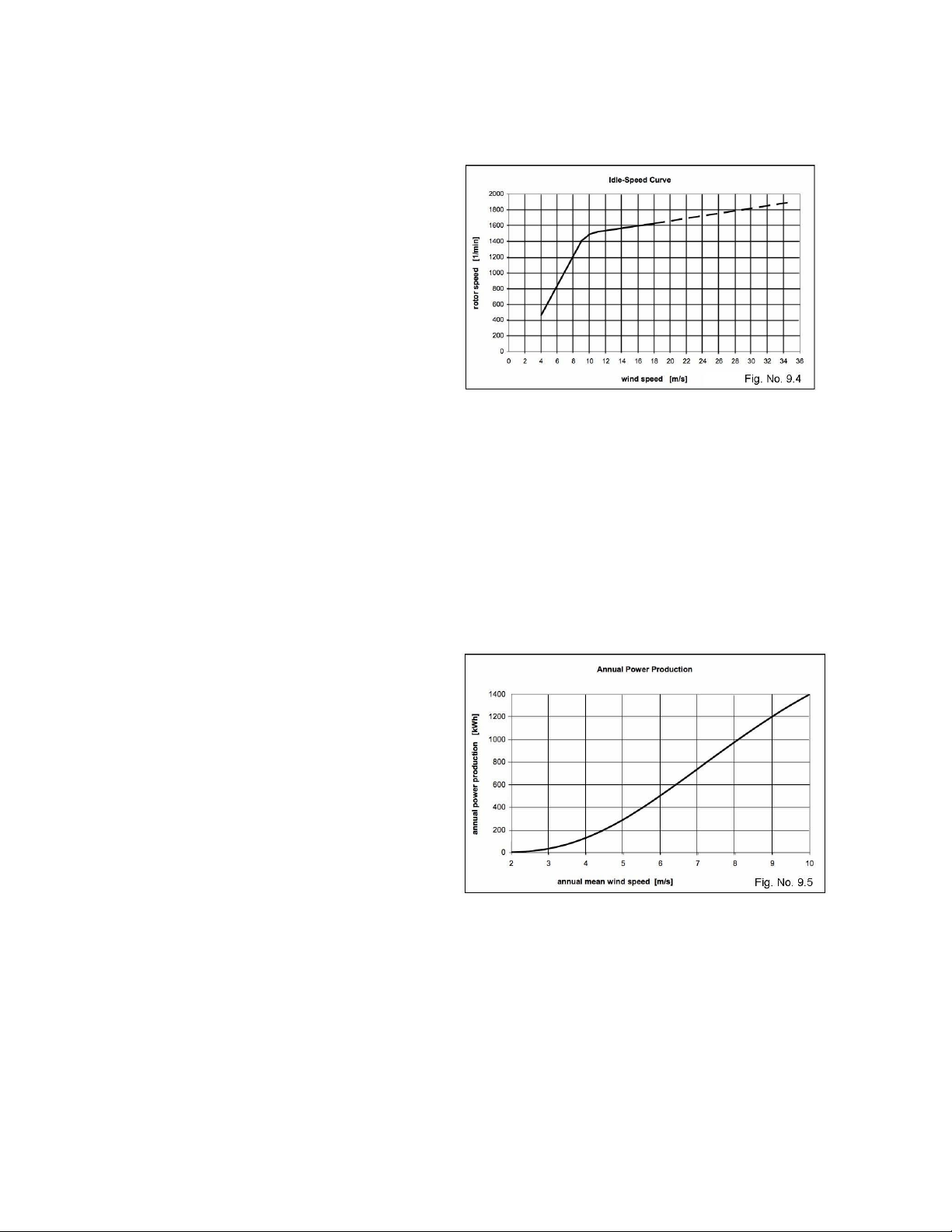
42
9.4 Over-Speed Protection
The Superwind 350/48V is
equipped with a rotor control
system which incorporates an
over speed control mechanism.
The over speed controller
works at all wind speeds, even
without an electrical load on the
turbine. Although it is
not a normal operational mode,
an unloaded turbine
(meaning the turbine is
disconnected from the
batteries) could occur under
certain conditions (e.g. blown fuses, malfunction of the charge regulator or electrical
failures caused by overvoltage or a lightning strike). It is important to avoid an
unloaded turbine condition at all times. The rotor control system responds to both
aero dynamical and centrifugal forces affecting the rotor blades. Due to the special
geometric rotor blade layout and matched rotor controller mechanism, the rotor at noload operation first accelerates to an increased idle-speed. The idle-speed will be kept
on a nearly constant level, speeding up only slightly during increases in wind speed.
In this way the rotor control system provides extra protection against high centrifugal
forces during no load operation, ensuring a very high level of safety and survivability
9.5 Annual Power Production
In DC-systems the electrical
power is the product of voltage
and current. Actual output
however, is a function of
generator speed and the load
connected, including the battery
state of charge (i.e. the electric
resistance of the consumers,
including the battery).
Therefore, the actual annual
power produced will be
determined by the wind
conditions at your site in
combination with what is being
powered and/or the battery bank being charged.
Fig. No. 9.5 shows the annual power production versus Rayleigh distributed annual
mean wind speeds.
© Copyright Mission Critical Energy Inc, 2019 Version 1-2019
www.superwind.com
Page 44
43
10.
INSPECTIONS AND MAINTENANCE
In some turbine applications (such as operation on a yacht) daily
inspections in and around the working area of a turbine is
recommended. Look for equipment or rigging that may have been
moved by others that could impact the turbine’s use and operation.
Keep the working area of the turbine free and clear!
Do not approach a turning rotor.
Never attempt to stop the rotor by hand.
Conduct inspections of the mast or wind generator on a calm
and windless day only.
Do not step or allow other persons to place themselves under
hanging loads (such as a tilted mast).
10.1 Periodic inspections
While your Superwind 350/48V has been designed to run for years without maintenance,
periodic inspections are required for reliability and safety. The inspections described below
should be performed annually or after any event that could result in damage to the unit
(lighting strike, foreign objects striking the rotor, etc).
Before performing any inspection, disconnect the Superwind/48 V from the batteries by
shutting down the rotor as described in Section 9.2).
10.1.1 Rotor blades
Check each rotor blade for damage (cracks, broken edges, unusual discoloring etc.).
If any blade damage is found, stop operation of your Superwind/48 V until the rotor
blade set has been replaced. As discussed previously, rotor blades must be replaced
as a set. Never mix rotor blades from different sets as decreased performance or
damage due to an unbalanced rotor will likely result.
Dirt on the blades affects airfoil performance and reduces power output. Remove dirt
by cleaning the blades with a sponge using soap and water. Do not use abrasive
cleaners or those containing strong chemicals.
10.1.2 Bolted connections
Check all accessible bolted connections, ensuring each is tightened to the correct
torque. Pay particular attention to the bolts securing the rotor blades, hub, wind vane
and yaw shaft. Refer to Section 7 for additional information.
10.1.3 Bearings
The generator and yaw shaft bearings are sealed and lifetime lubricated. Check the
bearings for smooth operation, clearance, or leakage. Defective bearings must be
replaced at an authorized service facility.
© Copyright Mission Critical Energy Inc, 2019 Version 1-2019
www.superwind.com
Page 45
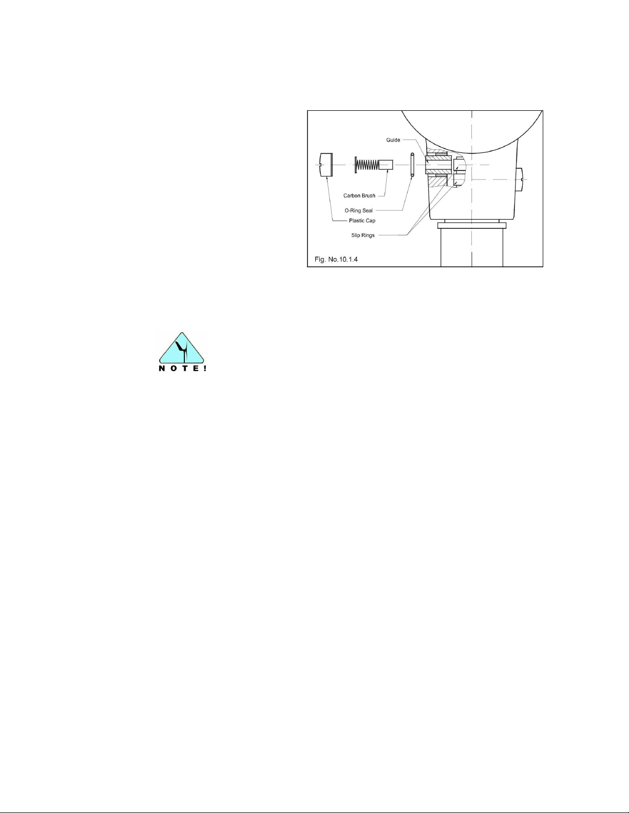
44
Use caution when unscrewing the two plastic screw caps. The
carbon brushes are spring loaded and can rapidly exit the unit,
resulting in loss of the brush assembly.
10.1.4 Slip rings
Electrical power is transmitted
from the yawing nacelle to the
stationary mast via slip rings.
The carbon brushes used to
accomplish this are designed to
last the life of the generator,
however periodic checks for
unusual wear or loss of contact
material is recommended.
Unscrew the two black
cylindrical screw caps (see fig.
10.1.4) and remove the carbon
brushes to inspect. Worn or
damaged carbon brushes must
be replaced. Carbon brushes should be replaced in pairs (replacement brushes are
sold in pairs and include new screw caps). Inspect the cap O-ring seals for damage
prior to reinstallation.
10.1.5 Corrosion protection
The generator housing and wind vane are constructed of a corrosion resistant, marine
grade aluminum alloy that is also powder coated for additional corrosion protection.
Inspect this powder coating and touch up any damaged areas noted with a suitable
lacquer paint.
All steel parts (e.g. ball bearings, shafts, axles and bolts) are stainless steel and need
no special corrosion protection.
10.1.6 Mast
Check the mast or support structure for damage, corrosion, loose hardware, etc.
Refer to the appropriate mast or support installation guides.
10.1.7 Electrical system
Electrical system inspections must be performed by qualified personnel. Before
performing any inspection, verify that all lines are safe and that the wind generator is
secured and cannot start unexpectedly.
Check all electrical connections, making sure that they are tight and free from
corrosion. Pay particular attention to battery terminals, which are especially prone to
corrosion. Clean all terminals of corrosion and coat with a suitable battery terminal
grease to prevent future corrosion.
© Copyright Mission Critical Energy Inc, 2019 Version 1-2019
www.superwind.com
Page 46
45
11.
TROUBLE SHOUTING
Never approach a turning rotor.
Never attempt to stop the rotor by hand.
Exercise extreme caution when working on the electrical
system as most of the lines are energized.
Never short-circuit the batteries.
Possible issue
Test
Solution
Not enough wind
Measure wind speed
Wait for more wind
Note: Start-up wind speed is
3.5 m/s [11.5 ft/s - 7.8 m/h]
(slightly higher during break-in
period)
Stop switch in STOP
position
Observe stop switch position
Place stop switch to RUN
position
Stop switch wired
incorrectly
Check stop switch connections
Wire stop switch correctly
Check the battery electrolyte levels (where applicable) and add distilled water as
necessary. Refer to the maintenance instructions provided by the battery
manufacturer for specific instructions.
10.2 Maintenance
Your Superwind 350/48V requires no special maintenance, however the above
inspections should be performed annually unless events dictate that additional
inspections should be conducted.
Most issues that occur after installation of your new Superwind 350/48V can be resolved by
following the below trouble shooting guide.
Use caution and remain aware of electrical and mechanical hazards at all times:
The following tools will be useful for troubleshooting:
A multi-meter (for checking voltage, current and resistance).
An anemometer (for checking wind speed).
11.1 Wind generator does not start
© Copyright Mission Critical Energy Inc, 2019 Version 1-2019
www.superwind.com
Page 47
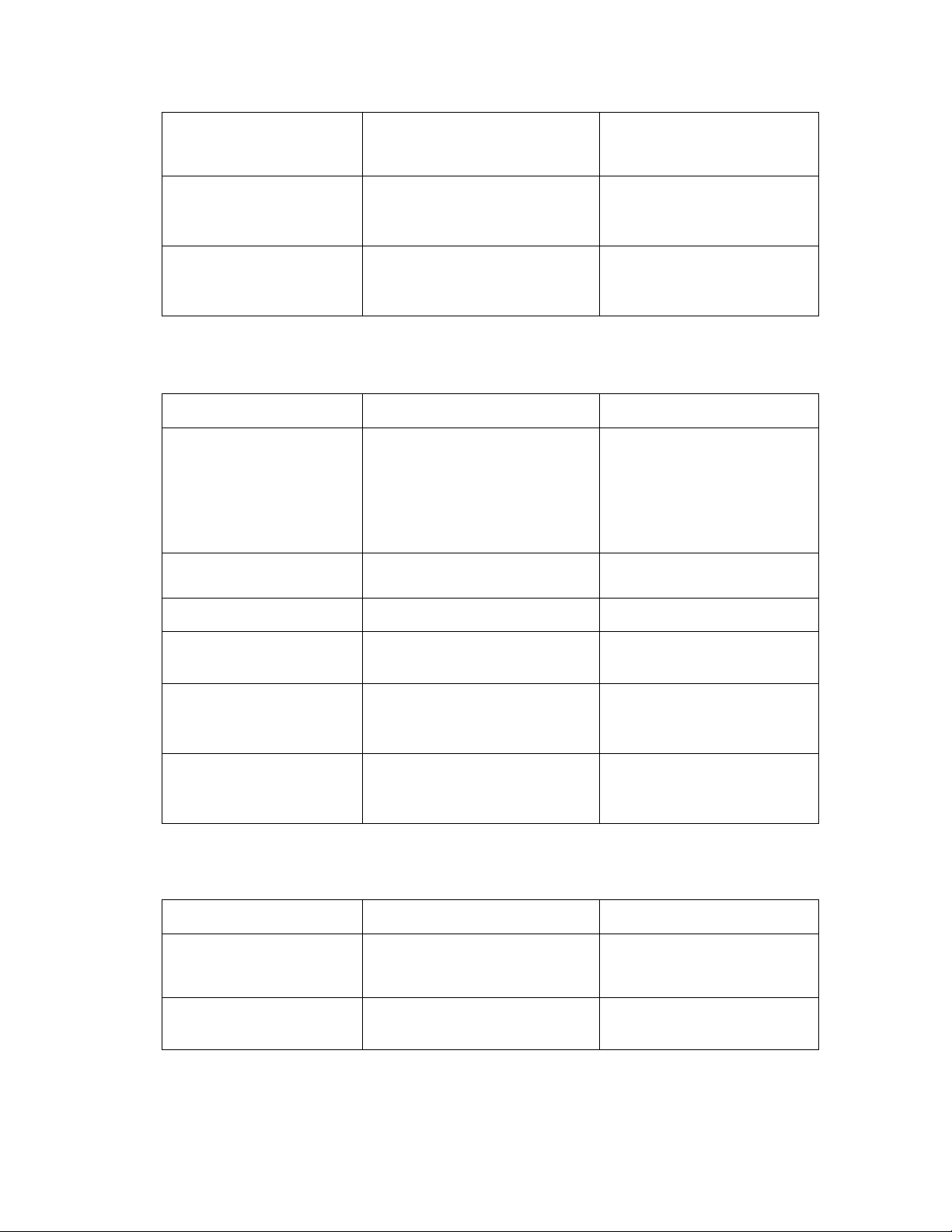
46
Debris between generator
housing and hub
Inspect the generator housing
and hub for debris
Remove the hub from the
generator shaft and clear the
debris
Generator shaft is stiff /
difficult to rotate.
Rotate generator shaft by hand.
(for this test the generator must
not be short-circuited)
Repair by authorized service
facility if defective
Yaw bearing is stiff, wind
generator does not follow
the wind direction
Move by hand
Repair by authorized service
facility if defective
Possible issue
Test
Solution
Not enough wind
Measure wind speed
Wait for more wind
Note: Minimal wind speed of
4.5 to 5.5 m/s [10 to 12 m/h]
is required for charge output
(depending on battery state of
charge)
Broken wire or loose
connection
Check all cables and
connections
Replace defective wire or
tighten loose connection
Blown fuse
Check fuses
Replace blown fuse
Worn carbon brushes
Check the carbon brushes and
the springs
Replace the worn carbon
brushes
Defective internal rectifier
No increased torque noted when
generator cables have been
short-circuited.
Repair by authorized service
facility if defective.
Loose stop switch
connections
Check tightness all stop switch
connections
Tighten loose stop switch
connections
Possible issue
Test
Solution
Bad electrical connection
Measure the electric resistance
of the cabling and devices
Replace defective lines or
devices, clean connectors
and terminals
Cable resistance too high
Check the cable cross section
(diameter) to cable length
Install larger gauge cables
with higher cross sections
11.2 No power output
11.3 Low power output
© Copyright Mission Critical Energy Inc, 2019 Version 1-2019
www.superwind.com
Page 48
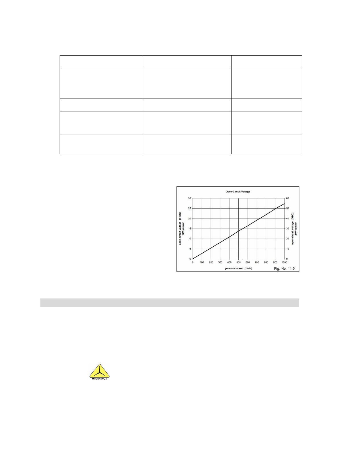
47
Possible issue
Test
Solution
Electrolyte level is low (wet-cell
type battery)
Battery is old or defective
Check electrolyte level (if
applicable).
Test the battery for proper
operation.
Add distilled water (if
applicable). Replace
battery if defective.
Blown fuse
Check fuses
Replace blown fuse
Charge regulator not connected
correctly
Verify charge regulator
connections are accurate (refer
to wiring diagram)
Connect the charge
regulator correctly
Charge regulator defective
See manual for trouble shooting
steps
Repair by authorized
service facility if defective
12.
REPAIRS AND RECOMMENDED SPARE PARTS
Do not open the hub housing.
11.4 Battery fails to fully charge
11.5 Checking open circuit voltage
A simple test to check for internal
generator defects is measuring
the open circuit voltage.
Disconnect the cables from the
generator and connect a
voltmeter to the positive and
negative line. To avoid injuries
dismantle the rotor blades
beforehand. Next, turn the hub by
hand and count the revolutions
within a certain period (e.g. 30
revs within 10 seconds = 180
rpm). Watch the voltage. The
voltage and the speed should
correspond to Fig. 11.5.
12.1 Repairs
If your Superwind 350/48V fails, you may replace all parts that are accessible from
the outside (e.g. rotor blades, carbon brushes, damping rings). Should any other
defect occur, please consult your dealer, an authorized service facility or the
manufacturer.
The hub is a safety relevant component requiring specialized knowledge and tools to
repair. To ensure safe operation, all repairs to the hub must be performed by
authorized service partners or the manufacturer.
© Copyright Mission Critical Energy Inc, 2019 Version 1-2019
www.superwind.com
Page 49
48
Spare Parts
Table No. 12.2
Item
No
Description
Part No.
1
Set of rotor blades (including M6 x 25 socket cap screws)
0300.05.00.00
2
Set of carbon brushes (including screw caps)
0300.01.03.03
3
Rectifier (including capacitors)
0300.01.04.01
4
Generator bearing (front)
0300.03.02.03
5
Generator bearing (rear)
0300.03.02.04
6
Set of damping rings (includes O-ring) 40 x 3
0300.02.01.02
7
Socket cap screw M8 x 80 V4A DIN 912
0300.04.01.10
8
Hexagon socket button head screw M6 x 6 V4A ISO 7380
0300.02.01.12
9
Hexagon socket button head screw M6 x 12 V4A ISO 7380
0300.02.01.10
10
Charge Controller SCR 48 V
SW35-SCR48v
11
Temperature Sensor
SW35-RTS25
12
Stop Switch
0300.12.00.00
13.
FREQUENTLY ASKED QUESTIONS
12.2 Spare Parts List
13.1 Basic use
Q. Can I mount a wind turbine on top my house?
A. The Superwind 350/48V is not for residential, grid-tied applications. This unit was
designed to charge batteries in off-grid environments only.
In situations where sufficient wind exists - such as farms, cabins, structures on cliff
edges, bluffs, or near the ocean – the Superwind 350/48V can be an asset.
Unless architecturally engineered to be part of the structure, no wind turbine should
be mounted to the roof of a house.
Q. What is the Superwind 350/48V used for?
A. The Superwind 350/48V was designed to be a commercial-grade micro wind
generator that has the ability to withstand extreme environmental conditions for many
years. Its applications are numerous, and it has been successfully utilized by
governments, militaries, disaster preparedness & response agencies, aquaculture and
agriculture industries throughout the world.
13.2 Installation
Q. How large should my battery bank be?
A. Battery capacity specifications are unique to each individual situation and therefore
cannot be easily determined by Superwind without more details. However, a typically
installation consists of a minimum of 400Ah (3 to 4 large batteries).
© Copyright Mission Critical Energy Inc, 2019 Version 1-2019
www.superwind.com
Page 50

49
Q. Do I need a charge controller, stop-switch, and resistor?
A. Installation of a charge controller, stop-switch, and power resistor is mandatory to
protect your batteries, as well as the turbine. A charge controller and diversion load
power resistor will safely dissipate excess power to avoid overcharging when the
batteries are completely full. A stop switch is mandatory and will allow you to safely
perform maintenance near or around your unit.
The use of a Superwind 48V SRC marine charge controller enables your system to be
completely autonomous and helps ensure a full state of charge and long battery life.
Q. What size wire do I run to the Superwind and the charge controller?
A. This Superwind manual specifies wire sizing for various distances (the wire run). The
proper wire size is important to optimize charging and eliminate the risk of fire. Refer
to the wiring specifications provided in this manual. Please do not hesitate to contact
us for recommendations regarding your specific project.
Q. Can I hook up to my hot water tank and avoid overcharging?
A. No. The internal electrical components in hot water tanks will not withstand
overcharging and will fail. This will, in turn, shed power to your batteries, which can be
very dangerous. Always install the provided Superwind power resistor for use as the
system diversion load.
13.3 Operation
Q. Can the Superwind be left ON while unattended?
A. The Superwind 350/48V kit allows for safe autonomous operation 24/7 when installed
properly with the SRC marine charge controller and diversion load resistor (included in
the kit).
The Superwind 350 is a commercial turbine designed for off-grid use in remote areas.
When installed properly, it is maintenance-free and can be left unattended. While you
can always use the safety-stop switch to temporarily shut down the unit, it is not
required.
Q. Do I need to tie down the Superwind in high winds or storms?
A. No. Tying down a Superwind 350/48V blade or vane can actually damage the unit.
Instead, utilize the safety-stop switch to enable the dynamic (magnetic) brake. The
Superwind 350/48V is designed to operate in wind conditions nearing hurricane force
speeds. In most circumstances, the unit can be left on without endangering the turbine
or the batteries.
Q. How long do the bearings last?
A. The Superwind 350/48V ‘auto-feathers’ during high wind conditions, which prevents
over speed of the turbine and lessens the wear on the bearings. This technology
allows Superwind units to have a long life – many have been in the field for over a
decade and are still going strong.
© Copyright Mission Critical Energy Inc, 2019 Version 1-2019
www.superwind.com
Page 51
50
Q. If one blade breaks do I replace just one?
A. Superwind rotor blades are manufactured as sets of three balanced by weight and
axial run-out. These 3 blades can be fixed to the hub in any order. However, do not
mix and match blades from different Superwind blades sets as this could cause the
rotor to be out of balance. This means that if a single Superwind blade is damaged,
the entire blade set needs to be replaced - not just one blade.
13.4 Troubleshooting
Q. The Superwind 350/48V is not producing power.
A. A common installation oversight preventing power production is related to the safety-
stop switch. Ensure all screws on the safety-stop switch are tightened down securely –
even the screws that are not in use. Loose screws can prevent a closed circuit, and
deny power throughout the system. Refer to the manual for specific stop-switch
procedures, if necessary. Again, two of the screws with no wire attached are actually
forming a jumper within the switch; ensure they are tight.
Q. How can I test to ensure the Superwind unit is producing power?
A. A clamp-on DC amp meter is an inexpensive tool that can be used to test the power
output from the unit. Make sure the amp meter that you purchase is capable of
reading DC amps.
If the batteries are fully charged and the unit is still working in efficient wind, the
charge controller will display an indicator light. When lit, a solid LED light represents a
full state of charge and indicates power is being diverted to the resistor.
NOTE:
The use of calibrated shunts – when in combination with other charging sources - is
NOT recommended for monitoring power output from the wind turbine. Calibrated
shunts will negatively affect the charge controller, causing significantly reduced
charging and incorrect readings. An amp coil sensor (often an option with many
battery monitoring systems) is recommended instead.
Q. The Superwind 350/48V is not producing the expected power
A. The Superwind 350/48V turbine has extremely high quality bearing sets to allow for a
long, nearly maintenance free service life. These special bearings do require some
weeks or months of a “break in period” to achieve the highest charging levels at lower
wind speed conditions. Leaving the Superwind turbine in the autonomous “Run”
position through all types of weather, including high winds and storms, will help
shorten this break in period.
© Copyright Mission Critical Energy Inc, 2019 Version 1-2019
www.superwind.com
Page 52

51
14. ABBREVIATIONS USED ON THIS MANUAL
A. ................... Answer
Ah ................... Ampere-Hours
AGM ............... Absorbed Glass Mat
AWG ............... American Wire Gauge
DC .................. Direct Current
e.g. ................. For example
EU .................. European Union
ft/s ................... Feet per second
ID .................... Inside Diameter
ITAR ............... International Traffic in Arms Regulation
Kg ................... Kilograms
Kn ................... Knots
Lb/ft ................ Pound per feet
lbf .................... Pound-Force
LED ................ Light-Emitting Diode
M .................... Meter or Meters
m/s .................. Meters per Second
mi/h ................. Miles per Hour
mm ................. Millimetre or Millimeter
mm2 ................ Square millimetres
OC .................. On Centre
Ohm ................ Unit of Electrical Resistance
OD .................. Outside Diameter
Q. ................... Question
PV ................... Photovoltaic
PWM ............... Pulse Width Modulation
revs ................. Revolutions
rpm ................. Revolutions per minute
Sch ................. Schedule
SCR ................ Superwind Charge Regulator
SOC ................ State of charge
V ..................... Volt (s)
VDC ................ Volt Direct Current
W .................... Watt (s)
ZVEI ............... German Federation of the Electric and Electronic
Industry
© Copyright Mission Critical Energy Inc, 2019 Version 1-2019
www.superwind.com
Page 53

52
15. SCOPE OF CHANGES
This section will reflect future changes to the present manual and the date when the new
version comes into effect.
Current Manual Version: Version 1-2019.
© Copyright Mission Critical Energy Inc, 2019 Version 1-2019
www.superwind.com
Page 54

53
superwind GmbH
Am Rankewerk 2-4
D-50321 Brühl
Germany
Tel: +49 / 2232 / 577357
Fax: +49 / 2232 / 577368
Email: [email protected]
www.superwind.com
Mission Critical Energy Inc
1801 North French Rd
Getzville, NY 14068 USA
Tel: +1-716-276 8465
Email: [email protected]
www.missioncriticalenergy.com
© Copyright Mission Critical Energy Inc, 2019 Version 1-2019
www.superwind.com
 Loading...