

Page 1

CERTUS WIRELESS REMOTE SYSTEM – INDUSTRIAL VERSION
Please read the manual thoroughly before installing or using the radio remote control. e customer must fully understand this manual. If
there are questions or concerns, please contact the company delivering the unit or the manufacturer. e radio remote unit is only allowed
for use in products whose use oers no danger for person or property if there is an interruption in transmission or receiving of the signal.
Additionally, there should be a manual emergency stop which is able to shut down the entire unit of machinery apart from the radio remote
stop. It is not allowed to use a radio remote control with machinery which could be subject to heightened accident risk. e manufacturer
cannot judge whether the proper procedure has been followed with the installation of the remote unit. Improper installation or improper
use of the remote unit by the user could result in injury or destruction of property. For that reason, the manufacturer cannot be responsible
for personal injury, property damage or loss of any time resulting from either improper installation, improper use or wrong use of the
product. Likewise, the manufacturer assumes no liability for damages resulting from improper maintenance. e manual should be kept
within easy reach and should be given to the next owner in case of a sale.
General Information
e system operates on a frequency of FM 869.85 MHZ (EU) or FM 914.5 (US) and utilizes frequency modulation
generally known as FM technology. While an FM signal is much less susceptible to electrical interference than an
AM signal, there can never be total protection against outside interference. Interference can result from the turning
on and o of electronic equipment and stronger interference can come from proximity to relay stations, industrial
equipment and types of computer equipment. Another interference factor could be the close proximity of strong
electric motors. e above factors should be considered when installing the wireless system. Also, the greatest range
will be achieved if the receiver is not enclosed in metal.
TABLE OF CONTENTS
1. Safety
1.1 Safety with this wireless unit
1.2 Safety warnings and tips
1.3 Potential areas of danger
1.4 Approved operators
1.5 Safety factors in the work area
1.6 Safety Components
1.7 Emergency Procedures
2. Instructions for Use
2.1 Transmitter 2.2 Receiver
2.1.1 Front and Back View
2.1.2 Technical Information
2.1.3 Setting Transmitter code
2.1.4 Optical Signals transmitter
2.1.5 Changing the Battery
2.1.6 Internal Antenna
2.1.7 Operation of the Transmitter
2.2.1 View and Parts
2.2.2 Technical Information
2.2.3 Setting Receiver code
2.2.4 Optical Signals Receiver
2.2.5 Internal Antennae
2.2.6 Operation of the Receiver
2.2.7 Allocation of Terminals
3. Tips for Connector allocation and start up
4. Using the Wireless System
4.1 Optical check
4.2 Safety Check and starting the system
5. Care and Maintenance
6. Troubleshooting Guide
7. Mounting the unit and running the safety test:
Page 2

1.1 Safety of this radio remote control
is wireless system is equipped with electronic safety devices
THE FOLLOWING IS IMPORTANT FOR YOUR SAFETY
Misuse or abuse of this equipment could result in injury to the user or others and/or
damage to property.
Everyone who uses this equipment must:
– Be qualied to use the machinery and have been introduced to the
wireless system
– Follow exactly the safety rules
– Have read the manual with care
Safety Factors
1) e product may only be installed, maintained and used by trained professionals.
Repairs must be done by Superwinch.
2) Never leave the transmitter unattended.
3) e transmitter is only to be used within the conners of the working space and
this space is to be clearly dened.
4) Using more than one transmitter for one receiver box is not allowed. If you own
or purchase a backup transmitter it is important to note: improperly stowing a
second transmitter is a security risk. When the system is rst put into use, the
backup unit should be tested then have it’s battery removed and the unit should
be stored in a secure place. If these safety regulations are not followed closely, the
machine could be set in motion by a non-professional by accident and this could
result in serious injury or death.
5) Both the transmitter housing and buttons should be checked on a daily basis and,
if damage is present, the transmitter should be taken out of use.
6) Also, the battery level must be checked daily. If the battery level is too low and
LED light 2 on the transmitter is ashing, then the battery should be changed.
7) e stop button should be checked before each shi to see if the signal is reaching
the receiver.
8) In an emergency situation, pressing the red emergency stop button should
immediately activate the stop relay in the receiver and the electrical current to the
machine should be cut.
Page 3

1.6 Safety Features
e machine will be brought to a stop if:
– the red stop button is activated
– the operating range is exceeded
– system encounters the same frequency from an outside source
– ve minutes go by since the last transmission
ese safety features are engineered into the system to protect personnel and
equipment and should never be changed, taken out or bypassed.
1.7 Emergency Procedure
If an emergency situation arises immediately press the emergency stop button (red)
on the transmitter. en follow the procedures as outlined in the manual for the
machinery being used.
LED 1
Stop Button
STOP
2. Instructions for Use
Before using the wireless unit, make sure to have read and fully understood this manual,
especially Chapter 1 on safety and safety features.
2.1 Transmitter
2.1.1 Front and Back views and operational controls
Illustration 1: Illustration 2:
Front of Transmitter Back of Transmitter
LED 1
Stop
Button
STOP
Button
1
Button
2
LED 2
Page 4

2.1.2 Technical Data – Transmitter
Frequency FM 914.5 MHZ
Number of Functions 2 plus emergency stop
Antennae internal (wire antennae 50mm)
LED light for transmission red
LED light battery level red
Battery 9 volt
Dimensions 120mmx65mmx25mm
Weight
Ingress Protection Level IP65
Operational Temperature -20 C to +50 C
2.1.3 Encoding the system
Before using the wireless system for the rst time or aer installation, the transmitter
must be matched to the receiver. To do this open the back of the transmitter by way of
the 4 small screws under the rubber protective cover. (see Illustration 4 Opening the
transmitter). Aer removing the back cover, you can see an 8 position code bank directly
above the battery. (see Illustration 3 A & B). Set your personal code, which must be the
same for the transmitter and for the receiver.
Illustration 3A Illustration 3B
Encoding must occur prior to connecting the receiver to the source of electricity.
2.1.4 Optical signals on the transmitter
e transmitter has 2 LED lights. (Illustration 1) LED 1 lights up when one of the buttons
is depressed. is signal shows the transmitter is sending a signal to the receiver. LED 2
shows the status of the battery. As long as this light does not go on when the transmitter is
being used, the battery has enough energy to work correctly. As soon as this light goes on
during operation, however, the battery must be changed immediately as further operation
of the unit cannot be guaranteed and injury to person or property might result.
Page 5
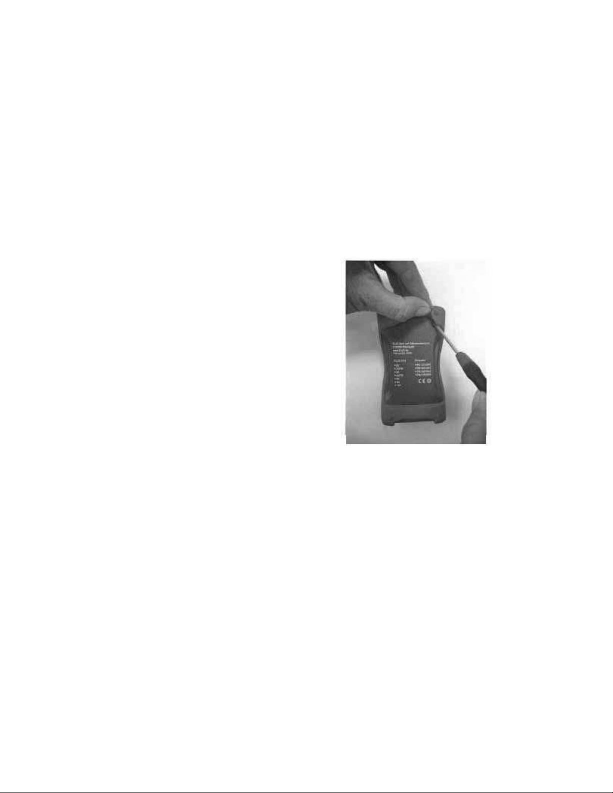
2.1.5 Changing the battery
To change the battery, open the back of the transmitter by removing the small screws
behind the rubber protective cover. (Illustration 4 opening the back cover) Aer
removing the cover, carefully remove the old battery and replace it only with one as
described by the manufacturer. (see 2.1.2 Technical Data) Before installing the new battery
insure that the connector is free from corrosion. Should this not be the case, any corrosion
can be easily removed by means of a small brush. Aer the new battery has been installed,
replace the cover carefully by means of the four small screws.
Aer changing the battery, please make sure the rubber seal on the transmitter is in
place correctly or the sealing of the unit cannot be guaranteed. Used batteries should
be disposed of according to national regulations.
Illustration 4:
Opening the Transmitter
and changing the battery
2.1.6 Internal Antenna
e transmitter utilizes an internal antenna. is antenna cannot be shortened, moved
or otherwise altered. e manufacturer has no liability if the antenna has been altered in
any way.
2.1.7 Operation of the Transmitter
e transmitter has 2 pressure buttons (green) as well as a stop (red). Each button
corresponds to a switch in the receiver and activates this switch as long as the button is
depressed. e stop button, when depressed, turns o all switches in the receiver. e
stop button always has priority so that it will turn o all switches even if one of the other
buttons is being operated. e stop button automatically puts the unit in standby mode.
Page 6
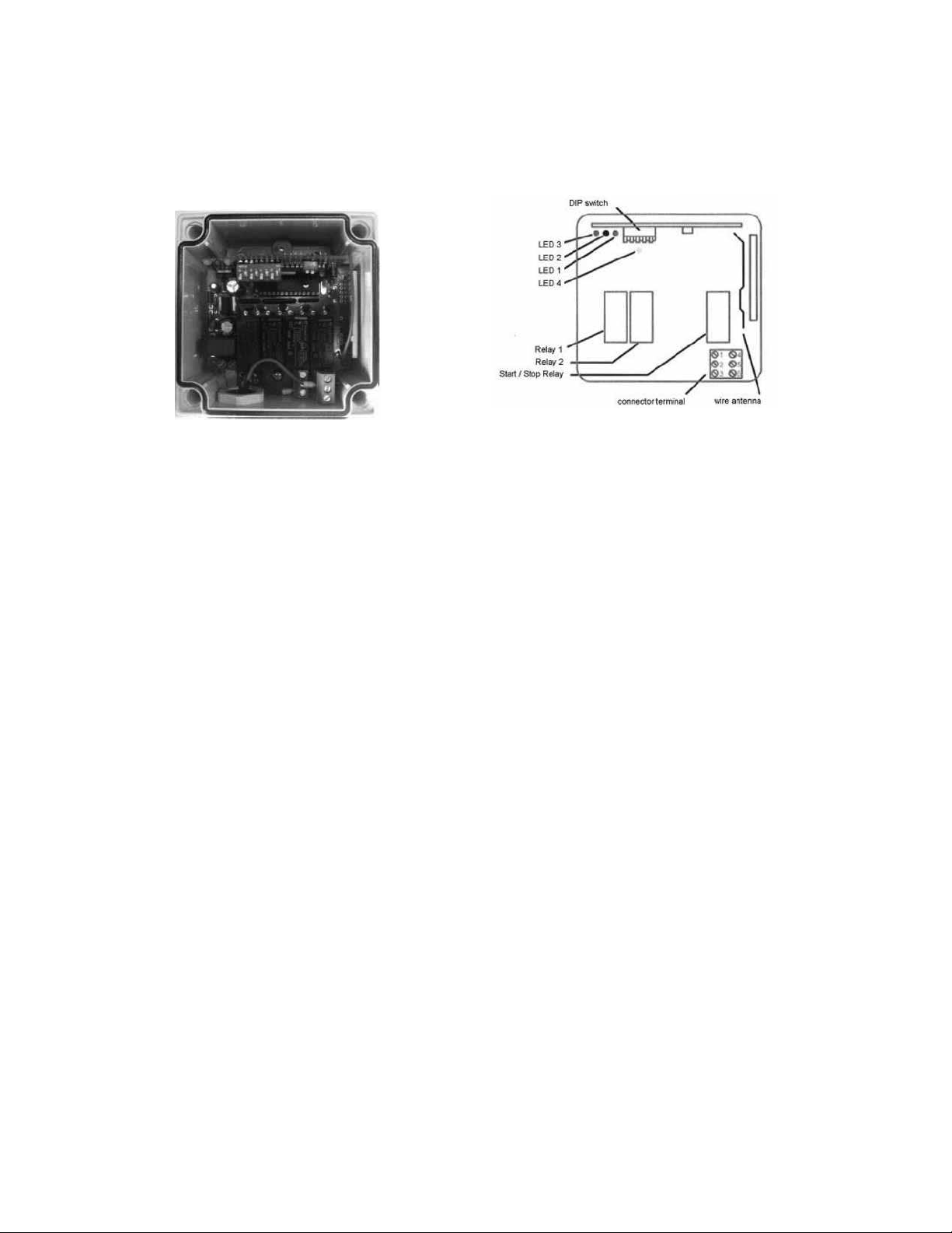
2.2 Receiver
2.2.1 Open view and components
Illustration 5: Receiver Illustration 6: Components – Receiver
Components of the receiver (Illustration 6 Components – Receiver)
DIP switch 8 pole DIP switch used to set personal code
LED 1 green light turns on when activated
LED 2 red light activated when receiving signal from transmitter
LED 3 green light activated when receiver is in ready mode
LED 4 yellow light activated when
Relay 1 activated when in ready mode if button 1 is depressed
Relay 2 activated when in ready mode if button 2 is depressed
Start/Stop Relay activated when emergency stop is pressed
Connector terminal Connection from the receiver
Wire antenna internal antenna to receive signal from transmitter
2.2.2 Technical Data - Receiver
Frequency FM 914.5 MHZ
Voltage supply 12 – 24 Volt DC
No signal current 12V 25mA, 24V 35mA
High load voltage Max. 24V DC
High load current Max. 5 amp pro Channel
Number of Functions 2 + Stop function
Antenna internal
LED Standby green
LED ready mode green
LED signal red
LED mode yellow
Encoding 8 bit DIP switch
Dimension 100mm X 100mm X 60mm
Weight 350g
Ingress protection IP65
Temperature levels -20C - + 50C
Page 7

2.2.3 Encoding the Receiver
Before using the wireless for the rst time or aer installation before the electricity is
delivered to the unit, the receiver must be matched to the transmitter. To do this, take o
the clear top of the receiver (use proper screwdriver). Aer the top has been taken o set
the code in the DIP switch. (see Illustration 6 Receiver components and illustration 5
Receiver picture) Set your personal code, which must be the same for the transmitter and
for the receiver. e code can only be set when there is no electrical source.
2.2.4 Optical signals in the Receiver
Easily seen on the top of the Receiver (le side) are three LED lights. ese signals show if the
unit is working correctly.
e green LED 1 shows voltage supply is present and the receiver is on.
e red LED 2 shows when a button on transmitter is being pressed. As long as the light is on
when the button is being pressed, the unit is working perfectly.
If the light starts to ash, there is interference in the signal or the signal is weak.
e red LED 3 is on when the receiver is functional. Only when this light is on can the signal be
received and the functions carried out.
2.2.5 Internal Antenna
e receiver utilizes an internal antenna. is antenna cannot be shortened, moved or
otherwise altered. e manufacturer has no liability if the antenna has been altered in
any way.
2.2.6 Functions of the Receiver
e receiver works with 2 relays and a start/stop relay. e relays switch the current to the
proper switch output. Please see the technical data Section 2.2.
e following functions are built into the receiver:
a) Standby Mode
When hooked up to the supply voltage, the receiver is in standby mode and LED lights 1
and 4 are on. LED 2 and 3 are not on. (see Illustration 8) In standby mode no function
can be varied out. e relays are not functional.
b) Operational Mode
In the operational mode the switching relays can be initiated through depressing the
buttons on the transmitter. is mode can be reached only from standby mode. In
operational mode, the LED 1, 3 and 4 are lit.
c) Automatic stop with frequency interference
e receiver can automatically mode to standby mode when another transmitter with the
same frequency is detected.
Page 8
d) Automatic stop upon reaching end of operating distance
e receiver can also move to standby automatically when the transmitter is used outside
of safe operating distance.
c) Time release
For safety reasons the receiver also moves to standby mode when more than 5 minutes
have elapsed between signals from transmitter to receiver.
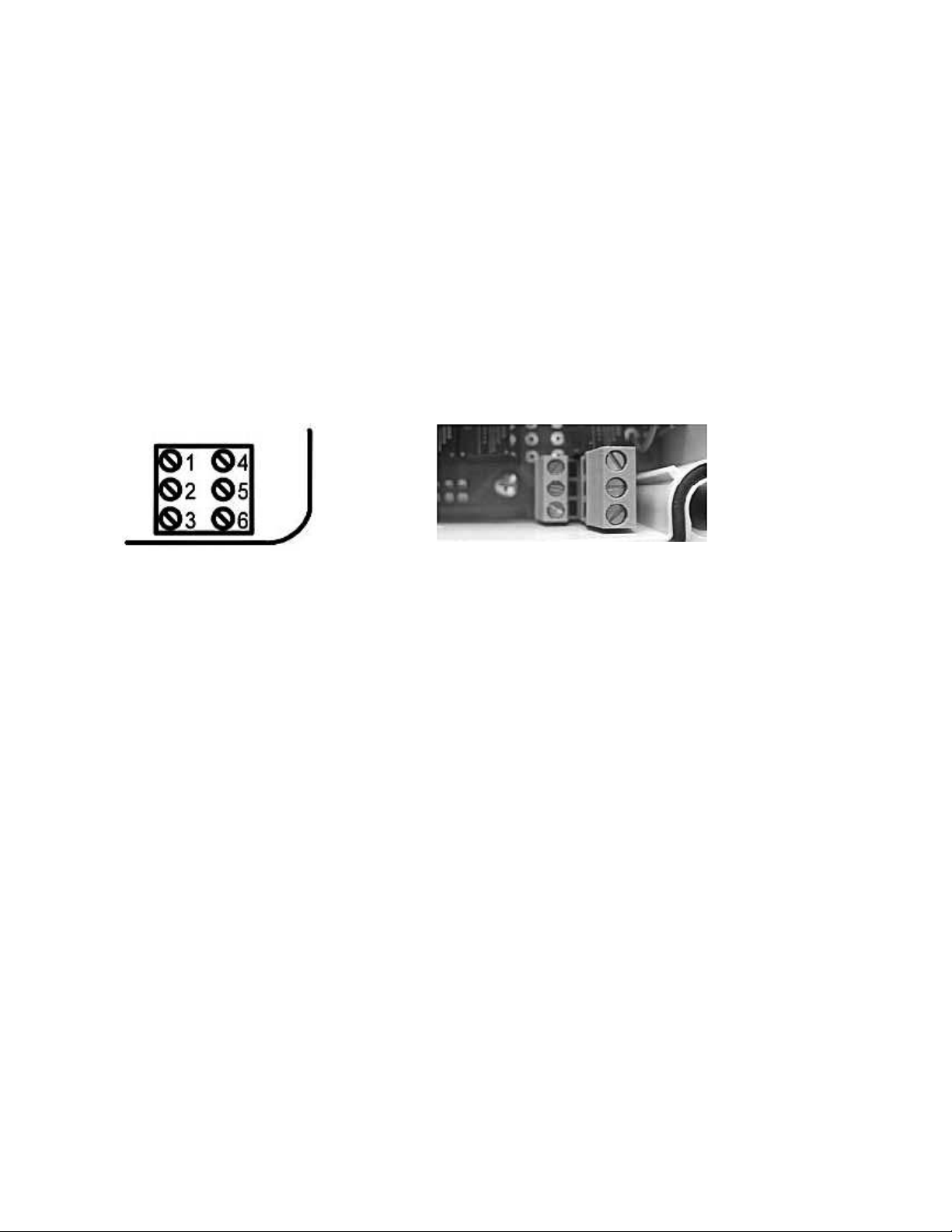
2.2.7 Allocation fop Terminals
ere is a six pole connection terminal in the receiver box at the bottom right.
Illustration 7: Illustration 8:
Connection terminal Photo of Receiver
Map of Terminals
Terminal 1 Output switching relay 1
Terminal 2 Output switching relay 2
Terminal 3 Ground
Terminal 4 open contact start/stop relay
Terminal 5 +12 – 24 V DC power supply
Terminal 6 Output switching relay 3 (optional)
3. Tips for Connector Allocation and start up
Mounting, setting up and maintenance of the system is only to be done by schooled
professionals. Furthermore, connecting the wireless unit to the machine being controlled
can only be done by a recognized expert in the type of machines being used.
– All work on the piece of machinery or on the receiver must be done with no
electricity connected.
e mounting position chosen for the receiver should be easy to reach and not inside the
vehicle. Also the receiver box should be able to be seen easily for diagnostic purposes. is
position should not be exposed to either direct sunlight or rainfall. e mounting surface
should be at to prevent contortion of the box which could allow water to enter the unit.
e mounting holes can be accessed by removing the cover. e cables going outward
from the box should be orientated downwards. Use the cable connections delivered with
Page 9

the system and run the wires through the connector units. If the receiver is being mounted
on a vehicle, there should be four rubber grommets between the box and the body of the
vehicle to reduce shock to the receiver.
It is important to operate the machine with no electrical connection prior to the
supply voltage being supplied to the receiver. Aer all components are connected the
supply voltage can be delivered to the receiver.
e eective operating distance of the transmitter and the receiver are partially dependent
on the landscape features and can vary greatly. Also electrical motors can add interference
and the receiver should not be mounted in close proximity to such motors. e greatest
operating distance can be achieved by mounting the receiver box high and away from
contact with metal surfaces.
4. Operation of the Radio Remote System
Before using the wireless system, the following safety steps must be followed:
4.1 Optical Test
– Check to see if the transmitter has been damaged
– Are all safety features available and working?
– Are all the rubber parts including protective cover and buttons undamaged?
If any parts of the system show damage or signs of wear they should be repaired before
further use.
4.2 Safety check and starting the wireless system
– Turn on the supply voltage to the receiver. LED lights 1 and 4 should be lit up.
– Press buttons 1 and 2 simultaneously for 3 or more seconds. LED light 3 should
light up and remain on.
– e start/stop relay engages and should remain engaged.
– Check to see if the operation of the transmitter corresponds to the operation of
the machinery.
– Check the stop function. Aer pressing the stop button, the machine should not
be able to be controlled by the transmitter.
– If the checks are nished and everything is functional, press buttons 1 and 2
again for 3 seconds.
e system is operational.
If the test is not positive then the machine must be stopped
immediately and the manufacturer should be contacted. Do
not work with a machine whose emergency stop is not working
correctly. Damage to persons and/or property could be the result.
Any action that does not follow these guidelines will result in the
voiding of the warranty.
Page 10

5. Care and Maintenance
Every year the wireless system should undergo a test administered by an expert in the eld
of wireless transmission.
An expert is dened as a professional with a background in wireless
transmission and with experience in this area. is person must
also possess knowledge of regulatory environment involved with
these products and with the safety rules and regulations of the
country in which the system is operating.
Care of the system components
Both the transmitter and the receiver should be washed with a moist cloth using no
further chemicals once a week.
6. Troubleshooting
Problem Possible Cause Solution
Receiver shows no reaction
aer supply current has been
connected. LED 1 does not
light up
Receiver shows no reaction
aer current is supplied and
button on transmitter is
pressed. LED 1 and 4 are on
but LED 2 does not light up
when button 1 or 2 is pressed.
Receiver can be taken out of
standby mode but quickly
shuts down again
System does not have enough
eective range
Supply current not available,
Connections reversed
Transmitter and Receiver are
not encoded correctly.
Another source is transmitting
on the same frequency
Receiver mounted incorrectly
Receiver surrounded in metal
Weak Battery
Check polarity.
Test current into receiver.
Turn on main power.
Compare codes
Encode units per 2.1.3 and 2.2.3
Deactivate other transmitter
See Mounting instructions
Change battery per 2.1.5
Page 11

7. Declaration for testing and mounting of the system.
e manufacturer assumes no responsibility and liability for installation of the wireless
system. e user must insure that the wireless unit and machinery to be controlled and its
components are compatible. e user is also responsible for the application of the safety
rules. (see Chapter 1 Safety)
Information for Machinery
Manufacturer ____________________________________________
Part Number/Type ____________________________________________
Manufacture Date ____________________________________________
Serial Number ____________________________________________
Information for Wireless System
Manufacturer ____________________________________________
Type ____________________________________________
System ____________________________________________
Serial Number Transmitter ____________________________________________
Serial Number Receiver ____________________________________________
Note:
e serial number for the transmitter can be found under the battery.
e serial number for the receiver can be found on the circuit board.
e person signing below brought the wireless service into use and is responsible that the
safety tests have been carried out per applicable laws and regulations.
Name ____________________________________________
Company ____________________________________________
Date ____________________________________________
Signature ____________________________________________
Page 12

NOTICE:
This device complies with part 15 of the FCC Rules [and with RSS-210 of
Industry Canada].
Operation is subject to the following two conditions:
(1) this device may not cause harmful interference, and
(2) this device must accept any interference received, including
interference that may cause undesired operation.
NOTICE:
Changes or modications made to this equipment not expressly
approved by, SUPERWINCH LLC, may void the FCC authorization to
operate this equipment.
NOTE:
This equipment has been tested and found to comply with the limits for
a Class A digital device, pursuant to Part 15 of the FCC Rules. These limits
are designed to provide reasonable protection against harmful interference when the equipment is operated in a commercial environment.
This equipment generates, uses, and can radiate radio frequency energy
and, if not installed and used in accordance with the instruction manual,
may cause harmful interference to radio communications. Operation of
this equipment in a residential area is likely to cause harmful interference in which case the user will be required to correct the interference
at his own expense.
NOTICE:
This Class (A) digital apparatus complies with Canadian ICES-003
Radiofrequency radiation exposure information:
This equipment complies with FCC radiation exposure limits set forth
for an uncontrolled environment. This equipment should be installed
and operated with minimum distance of environment. This equipment
should be installed and operated with minimum distance of (1.1cm)
between the radiator and your body. This transmitter must not be
co-located or operating in conjunction with any other antenna or
transmitter.
 Loading...