

USE AND WARRANTY DISCLAIMER
SuperTrapp Industries, Inc. of 4540 W. 160th Street, Cleveland, Ohio 44135 (SuperTrapp),
warrants its SuperTrapp products against defects in factory materials and workmanship for one
year from the date of purchase or until ownership in the product is transferred, whichever
occurs first, subject to limitations below.
Under this warranty, SuperTrapp will repair or replace defective, covered parts, at option, or
provide a replacement unit. SuperTrapp makes no warranty with respect to components of the
SuperTrapp product not manufactured by SuperTrapp, including, but not limited to the
following: clamps, nuts, bolts, packing, boots and hoses. Repair by SuperTrapp or replacement
are the exclusive remedies under this written warranty or any implied warranty. SuperTrapp
will not pay for the cost of removal or re-installation of the unit from any vehicle or for
delivery and pick up of the unit. To obtain service under this warranty, the original purchaser
must give specific written notice to his or her dealer within fifteen (15) days after discovery of
any claimed defect in the unit, and must return such unit to the dealer within a reasonable
time thereafter at the cost of the original purchaser.
This limited warranty is the only express warranty applicable to SuperTrapp product. Any
implied warranty of merchantability or fitness for a particular purpose is limited in duration to
the duration of this written warranty. Some states do not allow limitations on how long an
implied warranty lasts, so the above limitation may not apply to you.
SuperTrapp shall not be responsible for any consequential, special or incidental damages of
any nature including but not limited to the loss of use of any vehicle on which the unit may be
installed and the cost of obtaining another substitute product. Some states do not allow the
exclusion or limitation of incidental or consequential damages so this limitation or exclusion
may not apply to you.
This warranty is valid only if proper size of the unit is installed, operated and maintained in
accordance with factory instructions. This warranty does not cover any damage caused by (i)
modification or alteration of the unit; (ii) improper installation, maintenance, operation or use;
(iii) accident; (iv) servicing or repair by anyone other than SuperTrapp or its authorized agents.
CAUTION!: Warranty does not cover chrome discoloration. You can minimize this problem by
thoroughly cleaning and polishing the system before initial start-up, being sure the fuel
mixture is not too lean, and preventing long periods of engine idle.
This warranty gives you specific legal rights and you may also have other rights which vary
from state to state. Outside the United States, a different warranty may apply. For details,
please contact your authorized SuperTrapp distributor.
003-7172 11.20.08
SuperTrapp® Industries, Inc.
4540 W. 160th St. Cleveland, OH 44135
Phone: (216) 265-8400 fax: (216)265-0130
E-mail: sales@SuperTrapp.com www.SuperTrapp.com
Since 1975, SuperTrapp has built a reputation on innovation and technical superiority.
SuperTrapp
®
R&D is constantly designing, testing and improving; providing you with
the latest in state of the art performance engineering. SuperTrapp® products are
absolutely the best performance items available. They will provide years of troublefree service.
Installation Instructions
SuperTrapp SuperMeg 2:1
828-71572 Chrome 2:1 For Harley-Davidson® FLST/FXST
Softail® Models
827-71572
Black 2:1 For Harley-Davidson® FLST/FXST
Softail® Models
STOCK SYSTEM REMOVAL:
1. On 2007 and later models: Disconnect the oxygen sensors
from the front and rear head pipes.
2. Remove the stock exhaust system as described in your
owner’s manual. Retain the flange nuts for the new system
installation.
3. Remove the stock snap rings and flanges from the head pipes
and retain for the new system installation.
4. On 2007 and later models: Remove the oxygen sensors from
the front and rear head pipes and retain for new system
installation.
5. FLST MODELS ONLY. Remove right side floorboard. The
floorboard will be re-installed once the new system installation
is complete.
6. Remove the stock mount bracket and retain screws for new
system installation.
7. The exhaust gaskets should be inspected and replaced to
achieve a proper fit and seal. Replacement gaskets are available
from your Harley Davidson dealer, part number 65324-83A.
SYSTEM INSTALLATION:
1. Mount discs/end cap on muffler.
See disc installation diagram
2. Using stock muffler bracket mounting screws, install the new
muffler mount support bracket in the stock location. Torque
the screws to Harley Davidson specifications.
See owner’s
manual.
3. Install stock flanges on both head pipes.
4.
1984-2006 models: Apply anti-seize to the threads of the
oxygen sensor port plugs, supplied. Install the plugs into the
head pipes and tighten.
2007-later models: Apply anti-seize to the threads of the
oxygen sensors and install in new head pipes. (*VERY
IMPORTANT* Apply anti-seize to the threads of the oxygen
sensor ONLY. Contamination of the sensor probe can
adversely affect engine performance.)
5. Mount the head pipes using the stock nuts. DO NOT TIGHTEN.
6. Slide two T-bolts (supplied) into the slotted bracket on the back
of the muffler and install the T-bolt clamp (supplied) onto the
inlet end of the muffler.
7. Slide the muffler onto the outlet end of the head pipe. Align the
T-bolts with the holes in the mounting bracket. Install the flat
washers and locknuts onto the T-bolts. DO NOT TIGHTEN.
8. Align the system and tighten all fasteners and clamps starting
at the muffler and working up to the flange nuts.
9. On 2007 and later models: Reconnect oxygen sensors to
wiring harness.
HEAT SHIELD INSTALLATION:
1. Slide the hose clamps into the slots on the back of each
shield. Orient the clamps to gain the easiest access to tighten
them while in position on the head
pipe.
2. Install the heat shields on the head pipes and collector. The
tabs on the front of the collector shield must fit into the clips
on the end of the front and rear shields.
3. Tighten the shields starting with the rear shield, then the
collector shield, and finally the front shield. Align the shields
as you tighten to minimize the gap between the head pipe and
collector shields.
4. FLST SOFTAILS ONLY: Re-install the right side floorboard.
IMPORTANT: AFTER A SHORT RIDE CHECK AND RETIGHTEN ALL
FASTENERS.
TUNING TIPS:
For maximum performance gains, we suggest using 20 discs and
a free-flowing air filter kit with this exhaust system. As always,
making performance modifications may affect the fuel delivery
system of your motorcycle. It is recommended by Supertrapp to
have your fuel delivery system tuned to ensure maximum
performance and reliability. This work should always be
performed by a certified technician.
We DO NOT suggest removing the muffler packing material to
“get more noise”. Removing the packing will result in a loss of
power, discoloration of the finish on the muffler, and potential
failure of the mechanical portion of the core .
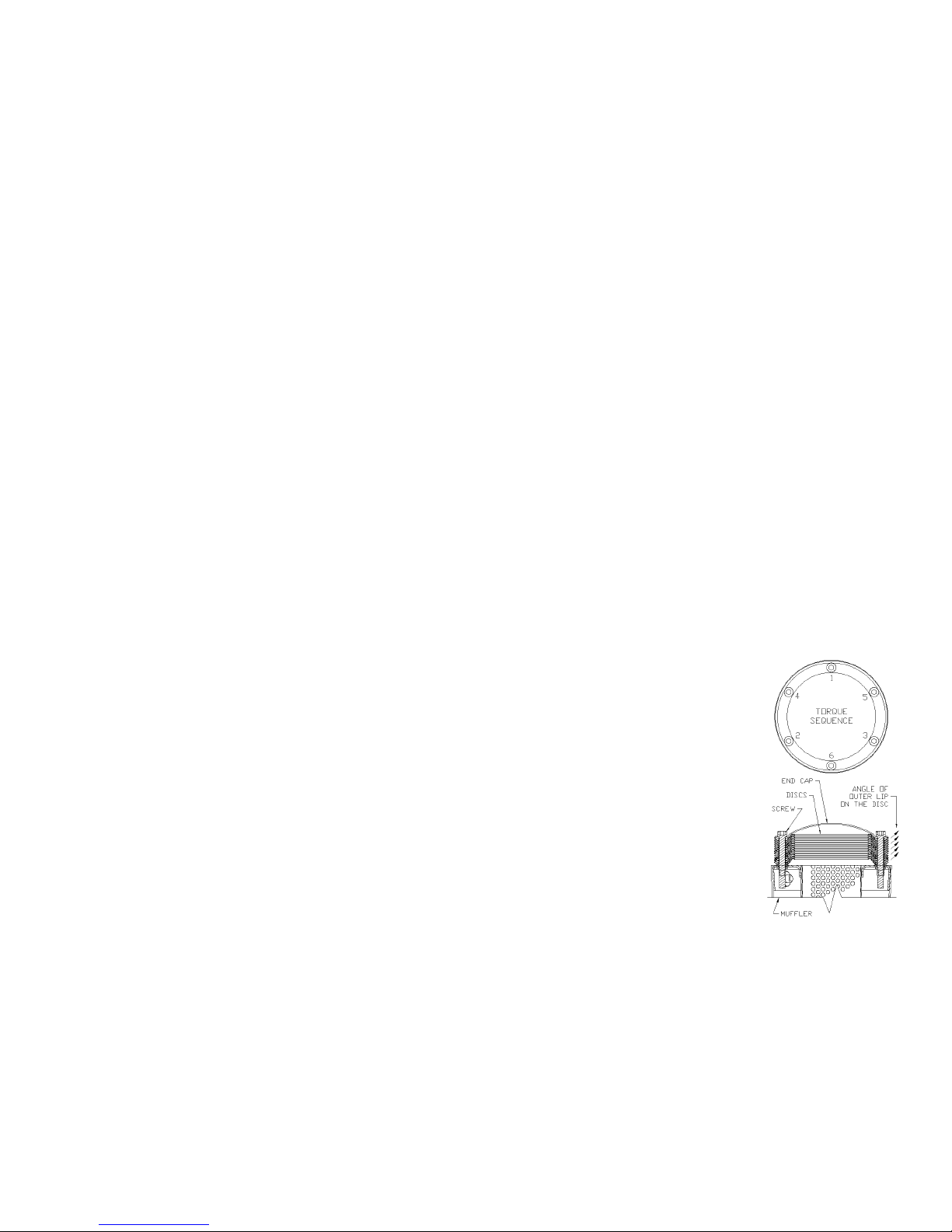
END CAP & DISC INSTALLATION:
1. Stand the muffler on the bench with
the outlet end pointing up.
2. Place the appropriate amount of
discs and end cap on the outlet of
the muffler. The flat surface of the
discs should be against the core
with the outer lip angled away from
the muffler. Align the (6) screw holes
with the threaded inserts in the
muffler outlet. (SEE DIAGRAM)
3. Insert the screws through the end
cap and discs and into the threaded
inserts in the muffler outlet. (SEE
DIAGRAM)
4. Tighten the screws evenly in a cross
pattern, SEE DIAGRAM. 4” discs
should be tightened to 15-25 in/lbs
and 5” discs to 40-50 in/lbs or once
the screw head contacts the end cap
tighten 2 full turns.
 Loading...