

Page 1

Instruction manual
MODEL NO: CS-164
Car Stereo Compact Disc
CD/CD-
R/CD
-RW/MP3 SD/MMC USB
Media Player with FM
/MW
Stereo Radio
Page 2

Car Stereo C
ompact Disc CD/CD-R/CD-RW/MP3 SD/
MMC USB Media Player with MW/ FM Stereo Radio,
Radio Data System
FUNCTIONS
The unit features a detachable front control panel,
FM/MW stereo, CD/MP3 player the following features:
Electronic Volume, Bass, Treble, Fader
and Balance
control
Loudness control Manual
FM Stereo/Mono selector
Soft touch power on/off switch
Manual tuning control
Band selector (BND) for MW/FM
Display control(Frequency, Station Name, Clock)
Clock Function in RDS
LOC Function in
RPT
CD Repeat Function
CD and MP3 files on CD/CD-R/CD-RW player function
Pre-amplified Line-out for external amplifier
Compact Disc mechanism
Detachable front panel protects against theft
Lighting system
RDS Function:
TA (Traffic Announcem
ent)
AF (List of Alternative Frequencies)
Page 3

Function..........................
2
Warnings........................
4
Drawings........................5
Location..........................
6
Installation
Precautions.....................
7
Mounting example...........
7
Detaching and attaching..
8
The front panel................
8
ISO connector.................
9
Maintenance...................10
Operation
Power on/off...................11
Select.............................11
Volume knob.........
........11
DSP function.................11
Loudness control...........12
ESP mode.....................12
Beep mode...................12
Stereo/Mono.................13
AF function.......................13
TA function.......................13
Tuning knob...
..................14
DSP button......................14
Mode button....................15
Band button.....................15
Skip forward/backward....15
LCD Display.....................15
Release button................15
CD slot............................16
CD eject button...............16
Pause button...................16
Intro button......................16
Repeat/Loc button...........16
Random button................16
Track up/down select.......16
Reset...............................17
Specifications...
................18
Page 4

The exclamation point within the triangle is a warning
sign alerting the user of important instructions accom
-
panying the product.
The lightening flash with arrowhead symbol within the
triangle is a warning sign alerting the user
of voltage in
side the unit.
The reduce the risk of electric shock, do not remove the
cover. No user serviceable parts inside the unit. Refer
all servicing to qualified personnel.
Invisible laser radiation when the unit is opened or interlocks def
eated.
Avoid exposure to laser beam. User of controls, adjust
ments or procedures other than those specified herein
may result in hazardous radiation exposure.
This unit must not be exposed to moisture or rain.
This unit should be positioned so that
it is properly
ventilated.
Do not expose this unit to direct sunlight or heat radiating sources.
Page 5
Page 6

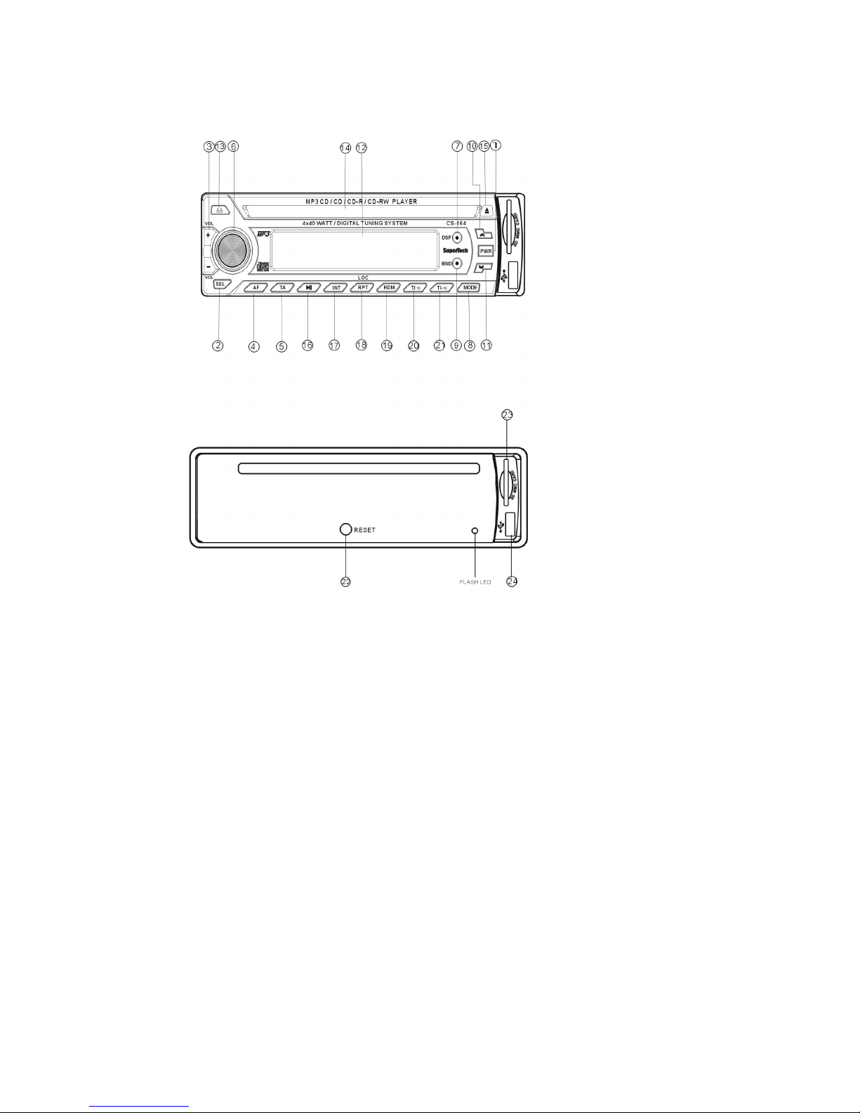
LOCATIONS OF CONTROLS
1. Power on/off button (PWR)
2. Select button (SEL)
3. Volume up/down button
4.AF (altern
ative frequencies)
5. TA Traffic announcement
6. Manual tuning knob
7. Display button (DSP)
8. Mode button MODE
9. Band button (BND)
10.Skip forward(
)
11.Skip backward (
)
12.LCD display
13.Release button
14.CD slot
15.CD eject button
16.Play/pause button
17.Intro button (INT)
18.Repeat button (RPT)
19.Random button (RND)
20.Skip 10 tracks up
21.Skip 10 tra
cks down
22.Reset button (not in common use)
23.SD/MMC card jack
24.USB slot
Page 7
INSTALLATION
PRECAUTIONS
Choose the mounting location carefully so that the
unit will not interfere with the normal driving functions
of the
driver.
Avoid installing the unit where it would be subject to
high temperatures, such as from direct sunlight or
hot air from the heater, or where it would be subject
to dust, dirt or excessive vibration.
Use only the
supplied mounting hardware for a safe
and secure installation.
Be sure to remove the front panel before installing
the unit.
Mounting angle adjustment
Adjust the mounting angle to less than 30.
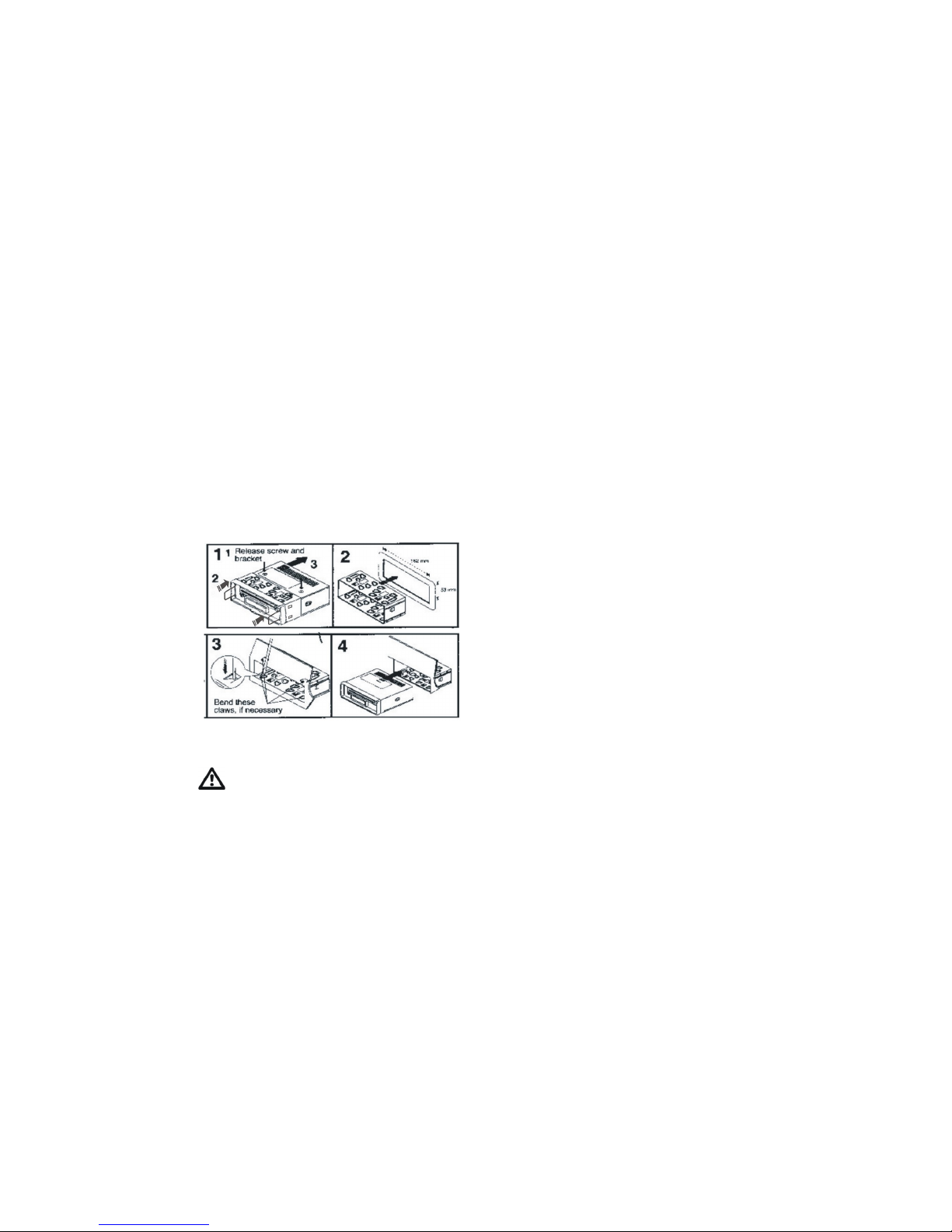
MOUNTING EXAMPLE
Installation in the das
hboard
Keep the release key in the safe place as you may
need it in future to remove the unit from the car.
Page 8
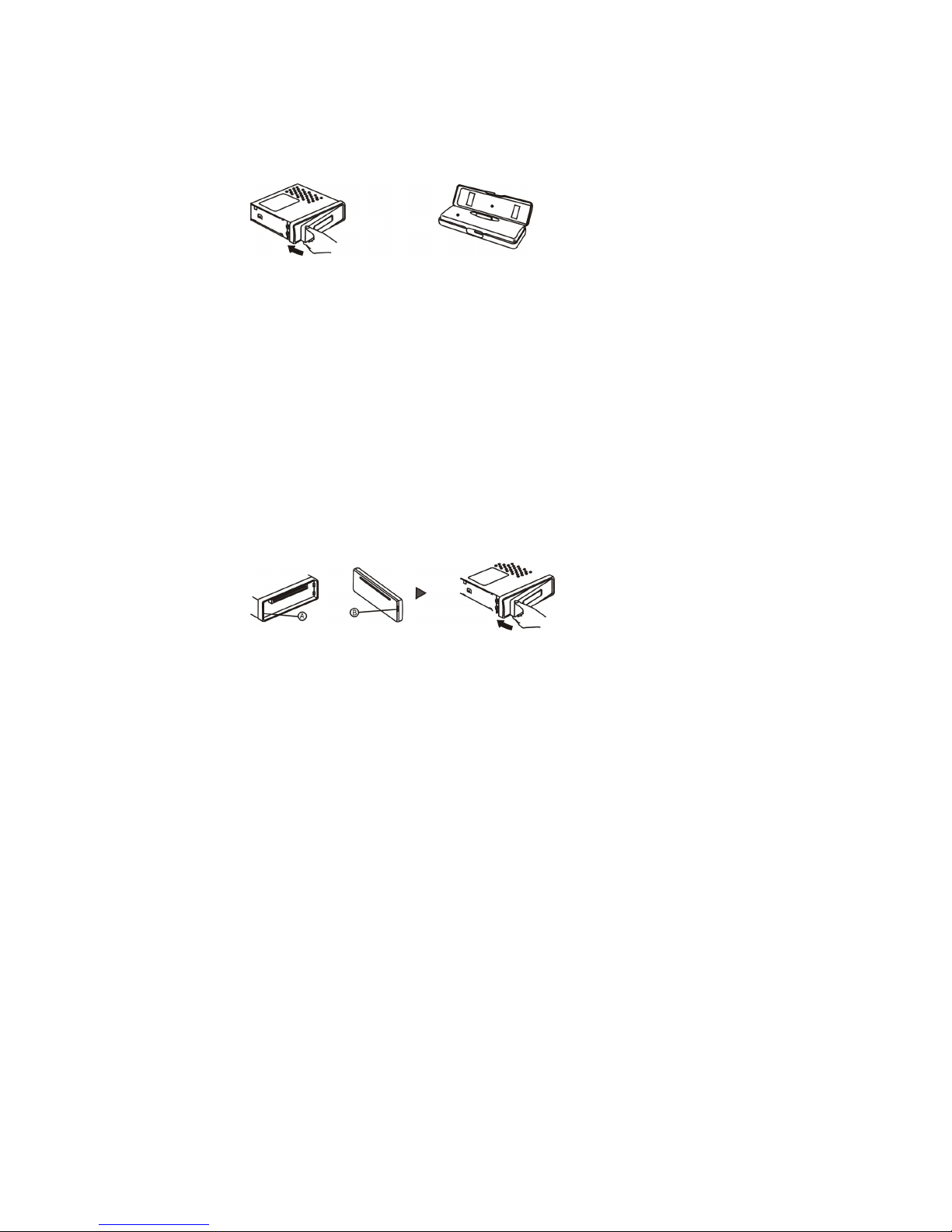
Detaching and attaching the front panel
The front panel of this unit can be detached in order to
prevent the unit from being stolen.
DETACH
ING THE FRONT PANEL
Before detaching the front panel, be sure topress the
PWR button to turn off the unit first.
Then press the button and detach the panel by pulling it
towards you as illustrated.
Note: Be sure not to drop the panel when detaching it
from the unit.
ATTACHING THE FRONT PANEL
Make sure the front panel is the right way up when atta
ching it to the unit as it cannot be attached upside down.
Bring side B of panel to side A of main unit. Inset the panel
in and push until it clicks. Pan
el is attached.
Notes:
Do not press the front panel hard against the unit when
attaching it. It can be easily attached by pressing it lightly
against the unit.
When you carry the front panel with you, put it in the
supplied front panel case.
Do not press hard or give excessive pressure to the
display window of the front panel when attaching it to the
unit.
Page 9
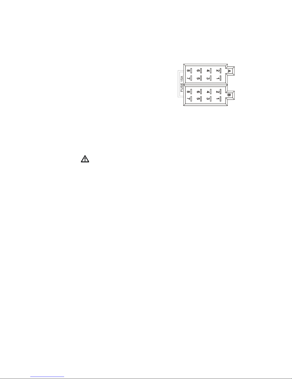
ISO CONNECTOR
RCA Jack Line Out(Rear)-Gray
:Red(right)
:White(left)
CONNECTOR A
1.
2.
3.
4. MEMORY +12V
5
. AUTO ANTENNA OUTPUT
6.
7.+12V (TO IGNITION KEY)
8. GROUND
The connector A no.7 must be connected by car
ignition key in order to avoid that car battery be-
comes weak when the car will be not used for long
pe
riod.
CONNECTOR B
1. REAR RIGHT SPEAKER(+)
2. REAR RIGHT SPEAKER(
-)
3. FRONT RIGHT SPEAKER(+)
4. FRONT RIGHT SPEAKER(
-)
5. FRONT LEFT SPEAKER(+)
6. FRONT LEFT SPEAKER(
-)
7. REAR LEFT SPEAKER(+)
8. REAR LEFT SPEAKER(
-)
Page 10

Maintenance
FUSE REPLACEMENT
If the fuse
blows, check the power connection and re
-
place the fuse. If the fuse blows again after the replace
ment, there may be an internal malfunction. In this case,
consult your near est repairing center.
Warning
Use the specified amperage fuse for each lea
d. Use of a
higher amperage fuse may cause serious damage
Page 11
OPERATING INSTRUCTIONS
1.POWER ON/OFF (1)
By pressing this key(1),the unit is switched on and off.
This unit is turned on by pressing any key.
Insert the front p
anel in the unit and push POWER button
in order on the unit.
Push PWR button newly in order to switch off the unit and
Push RELEASE button(13) to release the front panel.
NOTE: Never release the front panel when the unit is on.
Power rem ains on even
when car radio is off.
2.SELECT
3.VOLUME UP/DOWN
Press the VO(+) and VOL(
-) keys to control the VOLUME.
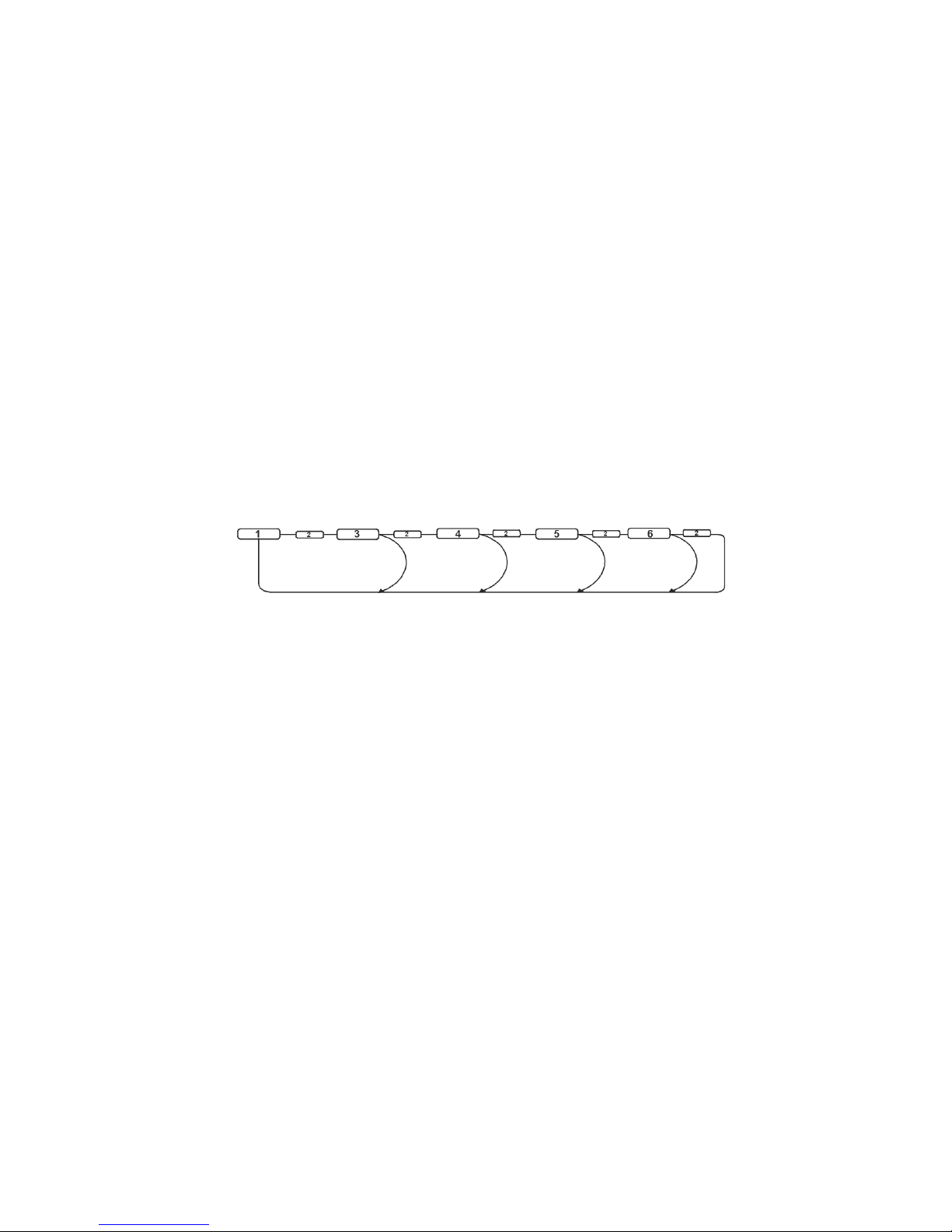
To select other functions, press the SEL(2) button shortly
until the desired functions is shown on the display.Figure 1
shows how control functi
ons are selected using the SEL button.
Fig. 1 Selection of sound control functions
1. VOLUME 2. SELECT 3. BASS 4. TREBLE 5. BALANCE
6. FADER VOL.UP Button (+) and VOL.DOWN Button (-).
Increase or decrease the volume by pressing + or -.
The
se buttons can be user to adjust the BASS, TREBLE,
BALANCE and FADER.
1) AUDIO DSP FUNCTION
When press the SEL button for more than 2 seconds, it is
activated as selecting mode of these function.
Page 12
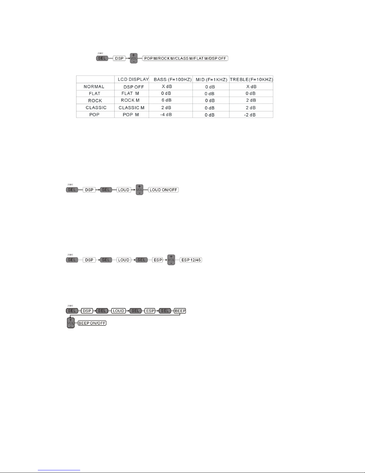
DSP can b
e selected by VOL+ and VOL-
key.
POP M
---ROCK M---
CLASS M
---
FLAT M
---
DSP OFF
2) LOUDNESS CONTROL
When press the SEL button for more than 2 seconds, it is
activated as selecting mode of these function.
LOUD ON/OFF mode is selected by VOL+ and Vol- key.
The bass and treble response will be boosted.
3) ESP MODE
When press the SEL button for more than 2 seconds, it is
activated as selecting mode of these function.
4) BEEP MODE
When press the SEL button for more than 2 seconds, it is
activated as sele
cting mode of these function.
Page 13

5)STEREO/MONO
When press the SEL button for more than 2 seconds, it is
activated as selecting mode of these function.
When FM stations are weak and are disturbed, listening can
be improved by selecting MONO.
U
SING THE RDS FUNCTION
What is RDS?
The RDS (Radio Data System) is a digital information system
developed by the EBU (European Broadcast Union). Piggy
backed on normal FM broadcasts, RDS offers a variety of
information services and automatic retuning func
tions for RDS
compatible car stereos.
In 1988, RDS became available in the United Kingdom, France,
West Germany, Ireland and Sweden. Test transmissions are
being conducted in many other European countries. It is
expected that RDS will be available in mos
t western European
countries in the near future.
4. AF FUNCTION
When press the button, it is activated as AF mode ON or OFF.
When AF station is received, AF segment is turned on in LCD
display.
5. TA FUNCTION
When press the button, it is activated as TA
mode ON or OFF.
When TA mode is on and traffic announcement is transmitted.
When the unit is in CD/MP3 mode, it will switch to radio mode
temporarily.
Page 14

If the volume level was under the threshold point, it will be
raised to the threshold point.
When TA station is received, TA segment is turned on in LCD
display.
6. TUNING KNOB
In radio mode, rotate the manual-tuning knob to select station
you desired.
7. DISPLAY (DSP)
Selects radio frequency ,clock display and ON PTY
To set the clock:
(1). Wit
h clock display selected, hold down the "DISP" button
until clock display starts flashing.
(2). Press VOL+ and VOL-
to change minutes and hours.
(3). Press "DISP" button to start the clock.
When this key is pressed it is operated as the conversion of
each display mode as follow.
1) Incase of receiving RDS station
TUNER MODE
PS
---TA---
FREQ
---CT
CD/MP3 PLAYER MODE
CDP
---PS---TA---
FREQ
---CT
2) In case of receiving NON RDS station
RADIO MODE
CLOCK
---
FREQ
---
NO PTY
CD/MP3 PLAYER MODE
CDP
---
FREQ
---CT---NO PTY
Each display time is several seconds, and come back to 1
St
position after several seconds.
CT=clock time FREQ=frequency
Page 15

8. MODE BUTTON (MODE)
By pressing this key, user can select RADIO mode or CD/
MP3/SD/MMC/USB PLAYER
mode.
9. BAND BUTTON(BND)
Each band is toggled cyclically by pressing this key FM1
-FM2
-FM3-
AM1-AM2.
10. 11.SKIP FORWARD(
) / SKIP BACKWARD ()
CD/MP3/SD/MMC/USB PALYER MODE
When press short, they are operated as TRACK UP/DOWN
mode.
When press longer than 1 secretary, they are operated as
CUE or REVIEW mode.
12. LCD DISPLAY
The liquid Crystal Display w
ill display the current state of the
unit.
13. PANEL RELEASE BUTTON
Press this button and the left-hand part of the panel will be
released.
CD CONTROL LOCATION OF PARTS
10.11. SKIP TRACK/SEARCH BUTTON
Forward and Backward track search (or changing songs)
Press the SKIP button(TUN
or TUN
) during play to go
to the desired track (song).
TUN
...backward TUN
...forward
When the desired music section of the disc is found, release
the button. Normal play will resume. When CD/MP3 play is
finishe
d, CD/MP3 mode automatically changes to radio mode.
Page 16

4. CD SLOT
15. CD EJECT BUTTON
Press the EJECT button (15) to remove the CD.
16. PAUSE BUTTON
During PLAY mode, press PAUSE button (16) to PAUSE .
Press it again to resume play.
17. INTRO
BUTTON(Preview all Tracks)
When this button (17) is pressed, INT indication is displayed
and the first several seconds of each track of the disc are
played.
Press again to stop intro and listen to track.
18. REPEAT BUTTON (RPT)
When this button is pre
ssed, RPT indication is displayed
and play of the selected track will be continually repeated
until the Track Repeat mode is cancelled by pressing RPT
button (18) again.
19. RANDOM BUTTON (RDM)
When this button is pressed ,RDM indication is displayed
and each track of the disc are played in random instead of
normal progression.
To cancel RANDOM mode, press RDM button (21) again.
20.21. 10 TRACK DOWN/UP SELECT
(In case of MP3/SD/MMC/USB files)
(20): 10 TRACK DOWN ( 21): 10 TRACK UP
Page 17

22. RESET
Reset button(22) is placed on the housing. The reset
button is to be activated for the following:
Initial installation of the unit when all
wiring is completed.
All the function button do not operated.
Error symbol on the display.
Page 18
SPECIFICATIONS
FM TUNER
Frequency Range 87.5-
108.0MHz
Usable Sensitivity 2 V at s/n 30 dB
Intermediate Frequency 10.7MHz
S/N Ratio >50dB
Image Rejection Ratio at 106KHz
>45dB
MW TUNER
Frequency Range 520-
1620KHz
Usable Sensitivity 40 dB at S/N 20dB
Intermediate Frequency 455KHz
S/N Ratio >50dB
Image Rejection Ratio at 1400KHz
>45dB
CD/MP3 PLAYER SECTION
Signal to S/N Ratio >60dB
Frequency Response 20Hz-
18KHz
REAMPLIFIED LINEOUT
Output 600mV(MAX)
Impedance 10Kohm
GENERAL
Power Supply Voltage DC 13.2 Volts Negative Ground
Speaker impedance 4
-8
Maximum Current Consumption 6A
Maximum Output Power 40 W X4CH
Memory current average 10.14MA
Specifications and the design are s
ubject to possible
modification without notice due to improvement.
If at any time in the future you should need to dispose of this
product. Please note that Waste electrical products should not
be disposed of with household waste. Please recycle whe
re
facilities exist. Check with your Local Authority or retailer for
recycling advice. (Waste Electrical and Electronic Equipment
Directive)
 Loading...