

Page 1
130-160
Installation Instructions
Part #SS451 - Rear Trac Bar
This product is designed to eliminate side shift of the rear axle
suspended on OEM leaf springs on the 2021 V-8 E-450
Installation time is 1.5 hours.
A qualified mechanic using normal automotive tools and following all safety
measures known should perform installation of this product.
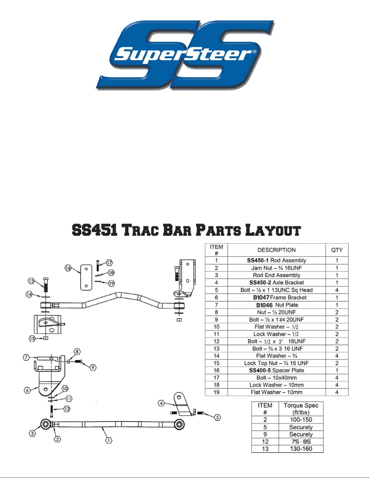
Components are shown below
Page 2

Figure 1
A. Preparation
Installation Instructions
Part #SS451 - Rear Trac Bar
Move the coach to a level, flat surface. If necessary, drive the rear wheels of the coach onto 4” high blocks
and set the brakes or you may drive the coach over a work pit and chock the front wheels. Block off adequate space at the rear of the coach to work.
B. Installation of the Axle Bracket
Begin by removing the 4 bolts, 2 on each side that hold the sway bar on the axle housing.
Take axle bracket and install ¾” bolt so that the bolt head will be on the axle tube side of the bracket (See
Figure #1). On the passenger’s side insert the mounting bracket underneath the sway bar bracket and
re-install bolts (See Figure 1). There are four holes drilled and tapped in the bracket to accept the four
square head set-screws. Put a drop of Locktite on each set-screw and thread into the tapped holes. Tighten the set-screws down equally until they contact the bracket that is welded to the differential. This will
stop the lateral movement of the bracket.
On the driver’s side, insert the spacer plate between the sway bar brackets and the differential (as shown
below). Install bolts supplied in kit.
Page 3
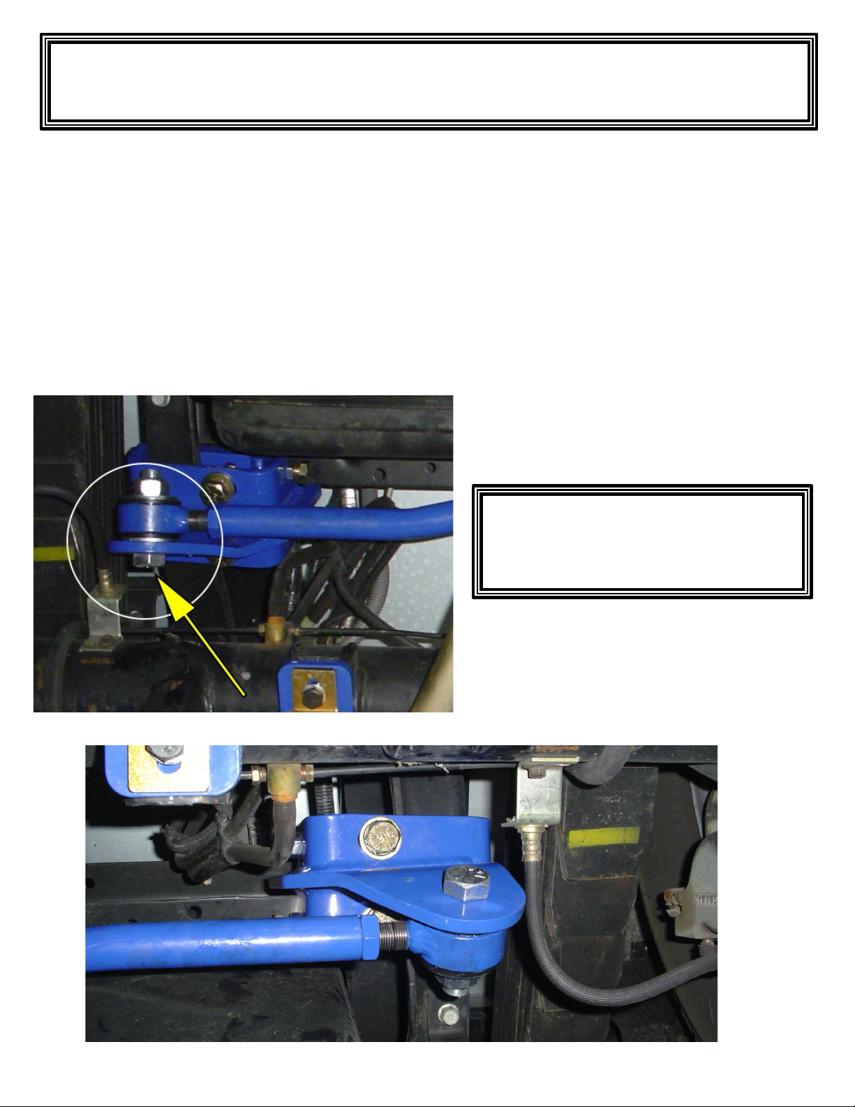
Figure 2
C. Installation of the Frame Bracket
Installation Instructions Part #SS451 -
Rear Trac Bar
Inserted As Seen Above To Prevent
Damage To Brake Line Attached To
Axle.
On the driver’s side, take frame bracket and install ¾” bolt so that the bolt head will be on the axle tube
side of the bracket (See Figure 2). Install the frame bracket and nut plate to the frame rail. The frame rail
must be between the nut plate and the frame bracket. The frame bracket is designed to mount to the bottom and sides of the frame rail. Position the bracket to clear brake hoses and axle. (place nut plate with lip
facing down and towards the center of the vehicle). Make sure not to contact any wires, brake lines, etc.
Install bolts through the bottom of the frame bracket and into the nut plate using supplied flat and lock
washers (just hand tight for now).
Install jam nuts to ½-20 bolts and install on the frame bracket. Tighten to push nut plate securely to the
inside of the frame rail. Next, tighten jam nut against frame bracket. Now tighten the bottom bolts securely.
Frame Bracket Bolt Must Be
Page 4
D. Installation of Rod Assembly
Installation Instructions
Part #SS451 - Rear Trac Bar
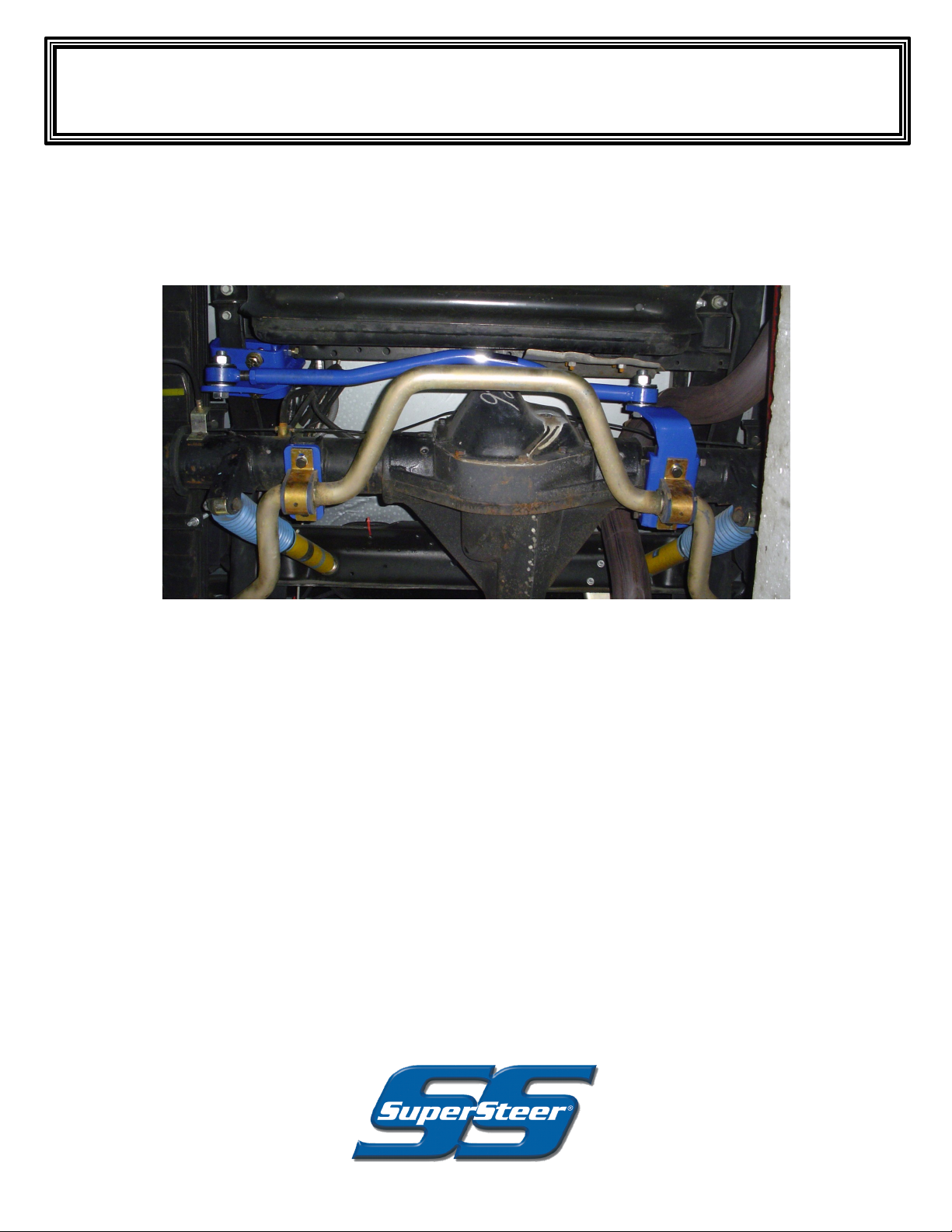
Position the rod assembly to the rear of the axle bracket and frame bracket. Install the rod assembly using
the 3/4” bolts, flat washers and lock nuts. Be sure that there is a flat washer on each side of the urethane
bushing. When adjusting the length of the rod assembly, it is necessary that the coach’s full weight be on
the suspension. Adjust to fit with the coach at normal ride height.
E. Torque Specifications & Follow-Up
Be sure to check all fasteners for tightness, including the jam nut on the rod assembly. Torque the ¾” rod
end bolt to 130 - 160 ft. lbs. Torque the jam nut to 100 - 150 ft. lbs. This completes the installation.
Test drive. To register your product for warranty purposes, go to the SuperSteer website at
www.SuperSteerParts.com and fill out the online registration card.
Re-check torque in 6 months.
Your comments are greatly appreciated.
Please feel free to contact SuperSteer
at 888-898-3281 or e-mail at
 Loading...