

Page 1

OWNERS MANUAL
Model: SPSS2-CA
Automatic Battery Charger/Maintainer
PLEASE SAVE THIS OWNERS MANUAL AND READ BEFORE
EACH USE. This manual will explain how to use the battery charger
safely and effectively. Please read and follow these instructions and
precautions carefully.
0099001421-00
Page 2

CONTENTS
IMPORTANT SAFETY INSTRUCTIONS......................................................3
PERSONAL SAFETY PRECAUTIONS ........................................................ 4
ASSEMBLY INSTRUCTIONS ......................................................................4
FEATURES ..................................................................................................5
CONTROL PANEL .......................................................................................5
GROUNDING AND AC POWER CORD CONNECTIONS .......................... 5
OPERATING INSTRUCTIONS ....................................................................6
MAINTENANCE AND CARE ........................................................................8
TROUBLESHOOTING .................................................................................9
SPECIFICATIONS .......................................................................................9
REPLACEMENT PARTS ..............................................................................9
BEFORE RETURNING FOR REPAIRS ....................................................... 9
LIMITED WARRANTY ................................................................................10
WARRANTY CARD .................................................................................... 11
Page 3

IMPORTANT SAFETY INSTRUCTIONS
WARNING – RISK OF EXPLOSIVE GASES
WORKING IN THE VICINITY OF A LEAD-ACID BATTERY IS DANGEROUS.
BATTERIES GENERATE EXPLOSIVE GASES DURING NORMAL OPERATION.
FOR THIS REASON, IT IS IMPORTANT THAT YOU FOLLOW THESE
INSTRUCTIONS EACH TIME YOU USE THE CHARGER.
To reduce the risk of a battery explosion, follow these instructions and
those published by the manufacturer of the battery and any equipment
you intend to use in the vicinity of the battery. Review the cautionary
markings on these products and on the engine.
WARNING: Pursuant to California Proposition 65, this product contains chemicals
known to the State of California to cause cancer and birth defects or other
reproductive harm. Wash hands after handling.
•Keep out of reach of children.
•Use the battery charger on 6 and 12V LEAD-ACID, GEL and AGM-type
rechargeable batteries with recommended rated capacities of 12Ah (6V) and
12-35Ah (12V), as used in automobiles, trucks, tractors, airplanes, vans, RVs,
trolling motors, etc. This charger is not intended to supply power to low-voltage
electrical systems, other than in a motor-starting application.
WARNING: Do not use battery charger with dry cell batteries that are
commonly used with home appliances. These batteries may burst and cause
injury or damage to property.
•Use only attachments recommended or sold by the battery charger’s
manufacturer. Use of non-recommended attachments may result in a re,
electric shock, or injury.
•Locate the battery charger’s power cord so it cannot be stepped on, tripped
over, or subjected to damage or stress.
•Do not operate the charger if it has received a sharp blow, been dropped,
or otherwise damaged in any way. Take it to a qualied professional for
inspection and repair.
•Do not disassemble the charger. Take it to a qualied professional when
service or repair is required.
•To reduce the risk of electric shock, unplug the charger from the outlet before
attempting any maintenance or cleaning.
•Do not use an extension cord.
•Always charge the battery in a well-ventilated area.
•Do not set the charger on ammable materials, such as carpeting, upholstery,
paper, cardboard, etc.
•Never smoke or allow sparks or ames in the vicinity of the battery or engine.
• 3 •
Page 4

WARNING: RISK OF EXPLOSIVE GAS.
•Operate the charger as far away from the battery as DC charger cables permit.
•Do not expose the charger to rain or snow.
•NEVER charge a frozen battery.
•NEVER overcharge a battery.
•NEVER set a battery on top of the charger.
•NEVER place the charger directly above a battery being charged. Gases from
the battery will corrode and damage the charger.
•NEVER touch the battery clips together when the charger is energized.
•When disconnecting the battery charger, pull by the plug, not by the cord. Pulling
on the cord may cause damage to the cord or plug.
•Do not operate the charger with damaged cord or plug.
•NEVER allow battery acid to drip onto the charger.
PERSONAL SAFETY PRECAUTIONS
•Wear complete eye protection and protective clothing when working near leadacid batteries. Always have someone nearby for help.
•Have plenty of fresh water, soap and baking soda nearby for use, in case
battery acid contacts your eyes, skin, or clothing. Wash immediately with soap
and water and seek medical attention.
•If battery acid comes in contact with eyes, ush eyes immediately for a
minimum of 10 minutes and get medical attention.
•Neutralize any acid spills thoroughly with baking soda before attempting to
clean up.
•Remove all personal metal items from your body, such as rings, bracelets,
necklaces and watches. A battery can produce a short circuit current high
enough to weld a ring to metal, causing a severe burn.
•Do not drop a metal tool onto the battery.
•If it is necessary to remove the battery from the vehicle to charge it, always
remove the grounded terminal rst.
ASSEMBLY INSTRUCTIONS
Remove all cord wraps and uncoil the cables prior to using the battery charger.
• 4 •
Page 5
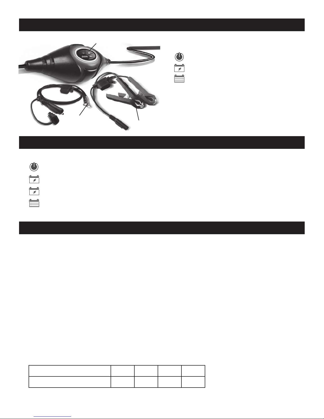
FEATURES
1
1. LED indicators:
AC POWER (red)
CHARGING (yellow/orange)
CHARGED/MAINTAINING (green)
2. Battery clamp quick-connect
3. Ring terminal quick-connect
3
2
CONTROL PANEL
LED INDICATORS
AC POWER (red) LED lit: There is AC power supplied to the battery charger.
CHARGING (yellow/orange) LED lit: The charger is charging the battery.
CHARGING(yellow/orange)LEDashing:The charger is in abort mode.
CHARGED/MAINTAINING (green) LED pulsing: The battery is fully
charged and the charger is in maintain mode.
GROUNDING AND AC POWER CORD CONNECTIONS
This battery charger is for use on a nominal 120 volt circuit. The electrical
outlet must be properly installed and grounded in accordance with all local
codes and ordinances. The plug pins must t the receptacle (outlet). Do not
use with an ungrounded system. NOTE: Pursuant to Canadian Regulations,
use of an adapter plug is not allowed in Canada. Use of an adapter plug in the
United States is not recommended and should not be used.
USING AN EXTENSION CORD
The use of an extension cord is not recommended. If you must use an extension
cord, follow these guidelines:
•Pins on plug of extension cord must be the same number, size, and shape as
those of plug on charger.
•Ensure that the extension cord is properly wired and in good electrical condition.
•Wire size must be large enough for the AC ampere rating of charger, as specied:
Length of cord (feet): 25 50 100 150
AWG* size of cord: 18 18 16 14
*AWG-American Wire Gauge
• 5 •
Page 6

OPERATING INSTRUCTIONS
IMPORTANT: Do not start the vehicle with the charger connected to the AC
outlet, or it could damage the charger.
CHARGING A BATTERY IN THE VEHICLE
1. Turn off all the vehicle’s accessories.
2. Keep the hood open.
3. Clean the battery terminals.
4. Place the charger on a dry, non-ammable surface.
5. Lay the AC/DC cables away from any fan blades, belts, pulleys and other
moving parts.
6. For a negative-ground vehicle (as in most vehicles), connect the
charger’s POSITIVE (RED) clamp to the POSITIVE (POS, P, +) battery
post. Next, connect the charger’s NEGATIVE (BLACK) clamp to the
vehicle chassis or engine block, away from the battery.
7. For a positive-ground vehicle, connect the charger’s NEGATIVE (BLACK)
clamp to the NEGATIVE (NEG, N, -) battery post. Next, connect the
charger’s POSITIVE (RED) clamp to the vehicle chassis or engine block
away from the battery. NEVER connect any clamps to the carburetor, fuel
lines or sheet-metal body parts.
8. Connect the charger to an electrical outlet. The AC POWER (red) LED
will light.
9. If you’ve connected everything correctly, the CHARGING
yellow/
(
orange) LED should be lit, indicating that the charger is charging, and the
AC POWER (red) LED will go off. If the CHARGING
LED does not
light, check the connections or have the battery checked/replaced.
10. When the battery is fully charged, the CHARGED/MAINTAINING
(green)
LED will pulse.
11. When charging is complete, disconnect the charger from the AC power,
remove the clamps from the vehicle’s chassis, and then remove the clamp
from the battery terminal.
CHARGING A BATTERY OUTSIDE OF THE VEHICLE
1. Place battery in a well-ventilated area.
2. Clean the battery terminals.
3. Connect a 24-inch long, 6-gauge (AWG) insulated battery cable to the
NEGATIVE (NEG, N, -) battery post (i.e., jumper cable) (not provided).
4. Connect the POSITIVE (RED) clamp to the POSITIVE (POS, P, +) battery post.
5. Position yourself and the “negative post extension” cable as far away
from the battery as possible, and connect the NEGATIVE (BLACK) clamp
to the cable’s free end.
• 6 •
Page 7

6. Connect the charger to the electrical outlet. The AC POWER (red)
LED will light.
7. If you’ve connected everything correctly, the CHARGING
yellow/
(
orange) LED should be lit, indicating that the charger is charging, and the
AC POWER (red) LED will go off. If the CHARGING
LED does not
light, check the connections or have the battery checked/replaced.
8. When the battery is fully charged, the CHARGED/MAINTAINING
(green)
LED will pulse.
9. When charging is complete, disconnect the charger from the AC power,
disconnect the negative clamp, and nally the positive clamp.
10. A marine (boat) battery must be removed and charged on shore.
USING THE QUICK-CONNECT CABLE CONNECTORS
Connect either of the two output cable assemblies to the charger in a matter of
seconds. Make sure to place the charger on a dry, non-ammable surface.
IMPORTANT: Never connect the clamp and ring terminal connectors together
for use in other applications, such as external battery or other power source
charging, or to extend the output cable length, as reverse polarity and/or
overcharge conditions will occur.
BATTERY CLAMP QUICK-CONNECT
1. Connect the end of the charger output cable to the end of the battery
clamp quick-connect.
2. Follow the steps in previous sections to connect the output clamps to
the battery.
3. After a good electrical connection is made to the battery, plug the power
cord into a grounded 120V AC electrical wall outlet.
RING TERMINAL QUICK-CONNECT
The ring connectors permanently attach to the battery, providing easy access
to quickly connect the charger to your battery. This application is appropriate
for motorcycles, lawn tractors, ATVs and snowmobiles.
1. To permanently attach to a battery, loosen and remove each nut from the
bolt at the battery terminal.
2. Connect the red POSITIVE connector ring to the POSITIVE battery terminal.
3. Connect the black NEGATIVE connector ring to the NEGATIVE battery
terminal.
4. Replace and tighten the nuts to secure.
5. Connect the cable to the end of the charger output cord.
Take care to keep the wires and plug away from metal and moving parts.
6. Plug the charger’s power cord into a grounded 120V AC electrical wall outlet.
AUTOMATIC CHARGING MODE
When an automatic charge is performed, the charger switches to the maintain
mode automatically after the battery is charged.
• 7 •
Page 8

CHARGE COMPLETION AND MAINTAIN MODE (FLOAT MODE MONITORING)
Charge completion is indicated by the CHARGED/MAINTAINING (green)
LED. When pulsing, the charger has stopped charging and switched to the
Maintain Mode of operation. NOTE: If the charger has to provide its maximum
maintain current for a continuous 12 hour period, it will go into Abort Mode (see
Aborted Charge section). This is usually caused by a drain on the battery, or the
battery could be bad. Make sure there are no loads on the battery. If there are,
remove them. If there are none, have the battery checked or replaced.
MAINTAINING A BATTERY
The SPSS2-CA maintains both 6 and 12 volt batteries, keeping them at full
charge. It is not recommended for industrial applications.
NOTE: The maintain mode technology allows you to safely charge and
maintain a healthy battery for extended periods of time. However, problems
with the battery, electrical problems in the vehicle, improper connections or
other unanticipated conditions could cause excessive current draws. As such,
occasionally monitoring your battery and the charging process is required.
DESULFATION MODE
If the battery is left discharged for an extended period of time, it could become
sulfated and not accept a normal charge. If the charger detects a sulfated
battery, the charger will switch to a special mode of operation designed for
such batteries. If successful, normal charging will resume after the battery is
desulfated. Desulfation could take up to 10 hours. If desulfation fails, charging
will abort and the CHARGING
yellow/orange) LED will ash.
(
ABORTED CHARGE
If charging cannot be completed normally, charging will abort. When charging
aborts, the charger’s output is shut off and the CHARGING
yellow/orange)
(
LED will ash. To reset after an aborted charge, unplug the charger from the
AC outlet, wait a few moments, then plug it back in.
MAINTENANCE AND CARE
A minimal amount of care can keep your battery charger working properly for years.
•Clean the clamps each time you are nished charging. Wipe off any battery
uid that may have come in contact with the clamps, to prevent corrosion.
•Occasionally cleaning the case of the charger with a soft cloth will keep the nish
shiny and help prevent corrosion.
•Coil the input and output cords neatly when storing the charger. This will help
prevent accidental damage to the cords and charger.
•Store the charger unplugged from the AC power outlet, in an upright position.
•Store inside, in a cool, dry place. Do not store the clamps clipped together, on
or around metal, or clipped to the cables.
• 8 •
Page 9

TROUBLESHOOTING
PROBLEM POSSIBLE CAUSE REASON/SOLUTION
The charger will not
turn on when properly
connected.
I cannot select a 6V
or 12V setting.
AC outlet is dead.
Poor electrical connection.
The quick-connect inline
fuse may be blown.
Reversing the connections
at the battery will cause this.
The charger is equipped
with Auto Voltage
Detection, which
automatically detects the
voltage and charges the
battery.
Check for open fuse or
circuit breaker supplying
AC outlet.
Check power cord and
extension cord for loose
tting plug.
Check the fuse. If it is
blown, replace it with
one of the same size and
rating (2A/32V).
No problem; this is
normal.
CHARGING
(yellow/orange) LED
is ashing.
Indicates the charger is in
abort mode.
See “Aborted Charge”
in the OPERATING
INSTRUCTIONS section.
SPECIFICATIONS
Input voltage ................................................................. 120V AC @ 60Hz, 0.4A
Output voltage ...................................... 6V or 12V, with Auto Voltage Detection
Output current rating ..................................................1A @ 6V DC and 12V DC
REPLACEMENT PARTS
Battery clamp cable assembly .......................................................3899002668
Ring terminal cable assembly ........................................................2299002276
BEFORE RETURNING FOR REPAIRS
For troubleshooting info, contact customer service for assistance:
[email protected]•www.batterychargers.com
or call 1-800-621-5485, Monday-Friday 7:00am to 5:00pm CST
For REPAIR OR RETURN, contact Customer Service at 1-800-621-5485.
DO NOT SHIP UNIT until you receive a RETURN MERCHANDISE
AUTHORIZATION (RMA) number from Customer Service at Schumacher
Electric Corporation.
• 9 •
Page 10

LIMITED WARRANTY
WARRANTY NOT VALID IN MEXICO.
SCHUMACHER ELECTRIC CORPORATION, 801 BUSINESS CENTER DRIVE,
MOUNT PROSPECT, IL 60056-2179, MAKES THIS LIMITED WARRANTY TO
THE ORIGINAL RETAIL PURCHASER OF THIS PRODUCT. THIS LIMITED
WARRANTY IS NOT TRANSFERABLE OR ASSIGNABLE.
Schumacher Electric Corporation (the “Manufacturer”) warrants this battery charger
for ve (5) years from the date of purchase at retail against defective material
or workmanship that may occur under normal use and care. If your unit is not
free from defective material or workmanship, Manufacturer’s obligation under this
warranty is solely to repair or replace your product with a new or reconditioned unit
at the option of the Manufacturer. It is the obligation of the purchaser to forward the
unit, along with proof of purchase and mailing charges prepaid to the Manufacturer
or its authorized representatives in order for repair or replacement to occur.
Manufacturer does not provide any warranty for any accessories used with this
product that are not manufactured by Schumacher Electric Corporation and
approved for use with this product. This Limited Warranty is void if the product is
misused, subjected to careless handling, repaired, or modied by anyone other
than Manufacturer or if this unit is resold through an unauthorized retailer.
Manufacturer makes no other warranties, including, but not limited to, express,
implied or statutory warranties, including without limitation, any implied warranty
of merchantability or implied warranty of tness for a particular purpose. Further,
Manufacturer shall not be liable for any incidental, special or consequential damage
claims incurred by purchasers, users or others associated with this product, including,
but not limited to, lost prots, revenues, anticipated sales, business opportunities,
goodwill, business interruption and any other injury or damage. Any and all such
warranties, other than the limited warranty included herein, are hereby expressly
disclaimed and excluded. Some states do not allow the exclusion or limitation of
incidental or consequential damages or length of implied warranty, so the above
limitations or exclusions may not apply to you. This warranty gives you specic legal
rights and it is possible you may have other rights which vary from this warranty.
THIS LIMITED WARRANTY IS THE ONLY EXPRESS LIMITED WARRANTY
AND THE MANUFACTURER NEITHER ASSUMES OR AUTHORIZES ANYONE
TO ASSUME OR MAKE ANY OTHER OBLIGATION TOWARDS THE PRODUCT
OTHER THAN THIS WARRANTY.
• 10 •
Page 11
WARRANTY CARD
SAVE ON POSTAGE! ACTIVATE YOUR WARRANTY ONLINE –
THE QUICK & EASY WAY! Go to www.batterychargers.com to register your
product online. (No internet access? Send in the completed warranty card.)
5 YEAR LIMITED
REGISTRATION
WARRANTY PROGRAM
MODEL: _____________________ DESCRIPTION: ________________________
This is the only express limited warranty, and the manufacturer neither assumes
nor authorizes anyone to assume or make any other obligation. There is no other
This warranty is not transferable. Send warranty card only.
The warranty card should be submitted within 30 days of purchase. The customer
warranty, other than what is described in the product owner’s manual.
must keep the ORIGINAL receipt because it will be required for any warranty claims.
DO NOT SEND UNIT TO THIS ADDRESS FOR REPAIR.
Mail this card to: Schumacher Electric Corporation
801 Business Center Drive
Mount Prospect, IL 60056-2179
Name ______________________________________________________________
Street Address _______________________________________________________
City ________________________________State _________ Zip Code _________
Phone _____________________Email ___________________________________
Store Name Where Purchased ___________________ Date of Purchase _________
Store Location ____________________ UPC Number ________________________
• 11 •
For faster warranty activation, go to www.batterychargers.com to register your product online.
Serial Number ______________________________________ (SEE PRODUCT)
 Loading...