

D Elektrischer Rollladen-Gurtwickler GW60
Einbau- und Bedienungsanleitung ..................................................................... 1
EN Electric roller shutter belt winder GW60
Installation and operating instructions ...........................................................51
ES Enrollador de cinta de persiana electrónico GW60
Instrucciones de montaje y de uso ................................................................101
PT Enrolador eléctrico de fita de estore GW60
Instruções de montagem e utilização ............................................................151
PL Elektryczny zwijacz do rolet na taśmę GW60
Instrukcja montażu i obsługi ..........................................................................201
Artikel Nr. SR10060 / SR10065
BA10060-2B
Aufputzmontage Unterputzmontage

Sehr geehrte Kundin, sehr geehrter Kunde...
i
...vielen Dank, dass Sie sich für ein Produkt aus unserem Hause entschieden
haben. Wir danken Ihnen für Ihr Vertrauen.
Unser elektrischer Rollladen-Gurtwickler wurde nach neuesten technischen Erkenntnissen und gemäß unseren hohen Qualitätsstandards für Sie entwickelt.
Einfache Bedienung und ein hohes technisches Niveau vereinen sich im elektrischen Rollladen-Gurtwickler zu einem Qualitätsprodukt „Made in Germany“.
D
2

Inhaltsverzeichnis
i
D
i Sehr geehrte Kundin,
sehr geehrter Kunde... .......... 2
1. Gesamtansicht ...................... 4
2. Lieferumfang ......................... 6
3. Erklärung der verwendeten
Sicherheitssymbole ............... 7
4. Sicherheitshinweise .............. 8
5. Bestimmungsgemäße
Verwendung .......................... 9
6. Kurzbeschreibung ...............10
7. Allgemeine
Montagehinweise ...............12
8. Sie benötigen
folgendes Werkzeug ...........12
9. Unterputzmontage .............13
10. Aufputzmontage .................22
11. Drehrichtung prüfen und
korrigieren ...........................30
12. Endpunkte einstellen
12. Endpunkte einstellen
13. Manuelle Bedienung
13.1 Den Gurtwickler
bedienen .....................34
14. Automatikbetrieb;
Öffnungs- und
Schließzeit einstellen ..........34
15. Automatikbetrieb; Auto/
Manu - Umschaltung...........36
.......... 31
.......... 32
...........33
16. Sonnenautomatik
16.1 Sonnenautomatik
ein-/ausschalten ........ 38
16.2 Sonnenautomatik:
Grenzwert
einstellen .................... 39
17. Einstellungen löschen .........40
18. Den Unterputz Gurtwickler ausbauen
(z. B. bei Umzug) .................41
19. UP-Gurtwickler,
das Gurtband bei
Geräteausfall entfernen .....42
20. Den Aufputz Gurtwickler ausbauen
(z. B. bei Umzug) .................43
21. AP-Gurtwickler,
das Gurtband bei
Geräteausfall entfernen .....44
22. Was tun, wenn... ? ..............45
23. Technische Daten ................47
23.1 Abmessungen
Unterputzgerät .......... 48
23.2 Abmessungen
Aufputzgerät ..............49
24. Garantiebedingungen
................37
.........50
3
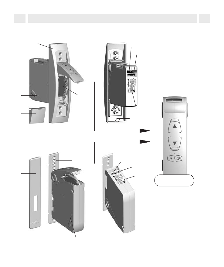
1. Gesamtansicht
i
D
Unterputzvariante
1.
5.
4.
Aufputzvariante
6.
5.
4
1. Montagerahmen
2. Bedienfeld
7.
8.
2.
3. Wickelradfach
4. Schraubenabdeckung
5. Getriebeentriegelung
6. Kabeldurchführungen
7. Netzteilanschluss
8. Sonnensensor anschluss
9. Typenschild (inkl.
Herstellerangaben
3.
9.
6.
1.
2.
3.
4.
7.
8.
9.
Legende
(s. Seite 5)
1. Wandhalter
2. Bedienfeld
3. Wickelradfach
4. Getriebeentriegelung
5. Kabelhalter
6. Wandhalterblende
7. Netzteilanschluss
8. Sonnensensor anschluss
9. Typenschild (inkl.
Herstellerangaben)
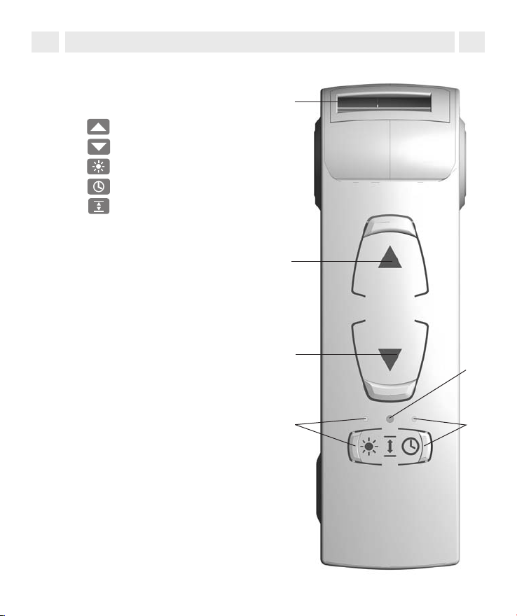
1. Gesamtansicht
i
Unterputz- und
Aufputzvariante
10. Gurtbandeinführung
11. Auf-Taste
12. Ab-Taste
13.
14. Uhrtaste mit Kontrollleuchte
15. SET-Taste
Sonnentaste mit Kontrollleuchte
D
10.
11.
12.
13.
15.
14.
5
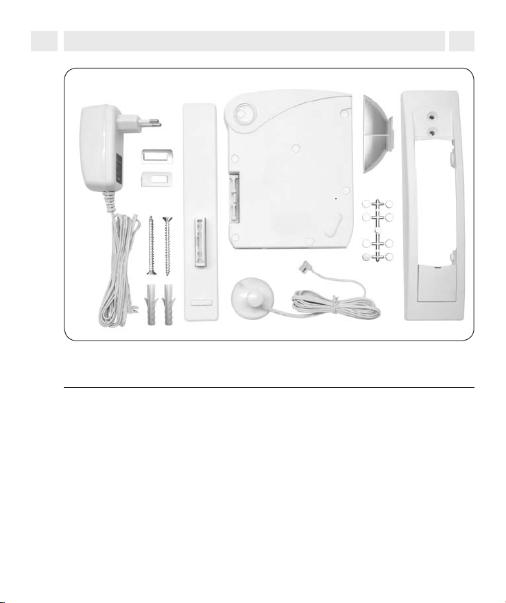
2. Lieferumfang
i
D
1.
4.
2.
3.
12.
11.
Legende
1. Netzteil 230 V/50 Hz / 24 V (DC)
2. Gurtbandeinlauf 23 mm
3. Gurtbandeinlauf 15 mm
4. Wandhalter für Aufputzmontage, inkl. Blende
(bei Unterputzmontage nicht zu verwenden)
5. Universal - Gurtwickler
6. Gurtbandadapter für Minigurtband 15 mm
7. Montagerahmen für die Unterputzmontage
(bei Aufputzmontage nicht zu verwenden)
8. Schraubenabdeckung
9. Schraubenkappen für die Gehäuseschrauben
10. Sonnensensor
11. Dübel
12. Montageschrauben
6
5.
10.
6.
7.
9.
8.
3. Erklärung der verwendeten Sicherheitssymbole
i
Lebensgefahr durch Stromschlag
Dieses Symbol weist Sie auf Gefahren durch elektrischen Strom hin.
Es fordert Sicherheitsmaßnahmen zum Schutz von Leben.
Wichtige
STOP
Sicherheitshinweise
Hier geht es um Ihre Sicherheit.
Befolgen Sie alle so gekennzeichneten Hinweise.
HINWEIS
So machen wir Sie auf weitere für die einwandfreie Funktion
wichtige Inhalte aufmerksam.
D
7
4. Sicherheitshinweise
i
Der Einsatz defekter Geräte kann zur Gefährdung von Personen und zu Sachschäden führen (Stromschlag, Kurzschluss).
Verwenden Sie niemals defekte oder beschädigte Geräte. Wenden Sie sich in
diesem Fall an unseren Kundendienst, s. Seite 50.
Verletzungsgefahr bei der Montage durch den plötzlich
anfahrenden Antrieb.
Führen Sie alle Montagearbeiten im spannungslosen Zustand aus.
Durch falsche Bedienung besteht Verletzungsgefahr.
STOP
◆ Es darf Kindern nicht erlaubt werden, mit der Rollladensteuerung zu spielen.
◆ Beobachten Sie während der Einstellung den Rollladen und halten Sie Per-
sonen fern, die durch plötzliches Nachrutschen des Rollladens zu Schaden
kommen können.
Nach der Norm EN 13659 muss dafür Sorge getragen werden, dass die für die
Behänge festgelegten Verschiebebedingungen nach EN 12045 eingehalten
werden. In ausgerollter Stellung muss bei einer Kraft von 150 N in Aufwärtsrichtung an der Unterkante die Verschiebung mindestens 40 mm betragen. Dabei ist
besonders darauf zu achten, dass die Ausfahrgeschwindigkeit des Behanges
auf den letzten 0,4 m kleiner als 0,2 m/s sein muss.
Die Netzsteckdose und das Netzteil müssen immer
frei zugänglich sein.
D
8

5. Bestimmungsgemäße Verwendung
i
Verwenden Sie den elektrischen Rollladen-Gurtwickler nur...
...zum Heben und Senken von Rollläden mit zulässigem Gurtband.
Verwenden Sie nur Originalteile des Herstellers.
Verwenden Sie nur Original-Ersatzteile, so vermeiden Sie Fehlfunktionen bzw.
Schäden am Gerät.
Als Hersteller übernehmen wir keine Garantie bei der Verwendung herstellerfremder Bauteile und daraus entstehender Folgeschäden. Alle Reparaturen am
elektrischen Rollladen-Gurtwickler dürfen nur vom autorisierten Kundendienst
durchgeführt werden.
Einsatzbedingungen
◆ Betreiben Sie den elektrischen Rollladen-Gurtwickler nur in trockenen
Räumen.
◆ Am Einsatzort muss bauseitig eine frei zugängliche 230 V/50 Hz Netz-
steckdose vorhanden sein.
◆ Der Rollladen muss sich leichtgängig heben und senken lassen. Er darf nicht
klemmen.
◆ Die Auflagefläche für den Gurtwickler muss eben sein.
Zulässige Gurtbänder
WICHTIG
Verwenden Sie nur Gurtbänder in den zulässigen Längen. Werden längere Gurtbänder eingezogen, kann das zur Beschädigung des Gurtwicklers führen.
D
Gurtbreite Gurtstärke Gurtlänge
15 mm (Minigurtband) 1,0 mm 5,5 m
23 mm (Standardgurtband) 1,0 mm 5,5 m
1,3 mm 4,5 m
9

5. Bestimmungsgemäße Verwendung
i
Zulässige Rollladenfläche
Leichte Kunststoffrollläden bis zu 8 m2.
Bei Aluminium- und Holzrollläden gelten andere Werte.
HINWEIS
Die Angaben sind Richtwerte und gelten für eine ideale Einbausituation. Auf
Grund von bauseitigen Gegebenheiten können die Werte abweichen.
6. Kurzbeschreibung
i
Der elektrische Rollladen-Gurtwickler 2 in 1 ist ein Rollladenantrieb für den Innenbereich. Mit seinen variablen Montagemöglichkeiten, kann er als Aufputzgerät
oder als Unterputzgerät verwendet werden. Die Stromversorgung erfolgt über
das beiliegende Netzteil.
Funktionsmerkmale und Steuerungsmöglichkeiten:
◆ Manuelle Bedienung (MANU)
◆ Automatikbetrieb (AUTO), je eine Schaltzeit für AUF (▲) und AB (▼)
◆ AUTO/MANU - Umschaltung
◆ Sonnenautomatik (Abdunklung bei Sonnenlicht mit Hilfe des Sonnensensors)
D
Hinderniserkennung
Die Bewegung des Gurtbandes wird überwacht. Trifft der Rollladen bei der
AB (▼)-Bewegung auf ein Hindernis, bewegt sich das Gurtband nicht mehr und
der Gurtwickler wird ausgeschaltet.
Nach der Abschaltung ist ein direkter Betrieb in die gleiche Richtung nicht mehr
möglich. Lassen Sie den Gurtwickler in die Gegenrichtung fahren und entfernen
Sie ein eventuell vorhandenes Hindernis. Danach ist der Betrieb in die ursprüngliche Richtung wieder möglich.
10

6. Kurzbeschreibung
i
HINWEIS
Bitte achten Sie nach einem Auslösen der Hinderniserkennung darauf, dass das
Gurtband (insbesondere das 15 mm Minigurtband) bei der nächsten Fahrt wieder
gleichmäßig aufgewickelt wird.
Blockiererkennung
Der Gurtwickler ist gegen Überlastung geschützt.
Blockiert der Antrieb bei der AUF (▲)-Bewegung (z. B. durch Vereisung) wird der
Gurtwickler ebenfalls ausgeschaltet. Nach Beseitigung der Überlastungsursache
ist er wieder in beide Richtungen voll betriebsbereit.
D
11
1
2
3
4
5
6 mm
7. Allgemeine Montagehinweise
i
Eine schlechte Gurtbandführung kann das Gurtband zerstören und den
Gurtwickler unnötig belasten.
Montieren Sie den Gurtwickler so, dass das Gurtband möglichst senkrecht
in das Gerät einläuft, Sie vermeiden dadurch unnötige Reibung und Verschleiß.
Bei falscher Montage können Sachschäden entstehen.
Während des Betriebes sind starke Kräfte wirksam, die eine sichere Montage
auf einem festen Untergrund erfordern.
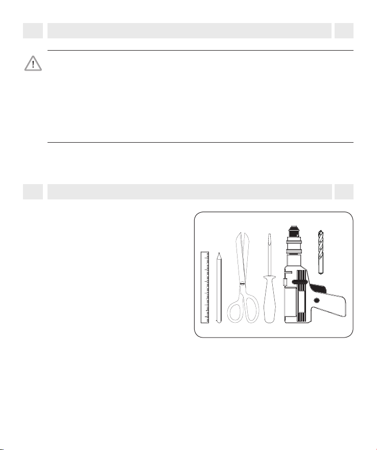
8. Sie benötigen folgendes Werkzeug
i
◆ Schraubendreher
◆ Schere
◆ Zollstock oder Maßband
◆ Stift
◆ Evtl. eine Bohrmaschine und
einen 6 mm Steinbohrer, falls
das vorhandene Lochbild nicht
passt oder der Gurtwickler
neu montiert wird.
D
12
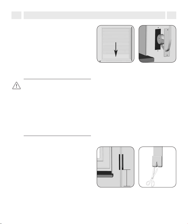
9. Unterputzmontage
i
Den alten Gurtwickler ausbauen,
1.
falls Sie eine bestehende Rollladenanlage umrüsten.
◆ Lassen Sie den Rollladen ganz
herunter, bis die Lamellen vollständig geschlossen sind.
◆ Bauen Sie den alten Gurtwick-
ler aus und wickeln Sie das
Gurtband ab.
Es besteht Verletzungsgefahr durch
die vorgespannte Feder im alten
Gurtwickler.
Die Federdose kann beim Herausnehmen unkontrolliert zurückschnellen.
Halten Sie die Federdose beim Lösen des Gurtbandes gut fest und
lassen Sie sie langsam zurückdrehen, bis die Federdose vollständig
entspannt ist.
Das Gurtband vorbereiten.
2.
◆ Schneiden Sie das Gurtband ca.
20 cm unterhalb des Gurtkastens ab.
◆ Schlagen Sie das Ende des Gurt-
bandes ca. 2 cm um und schneiden Sie in die Mitte einen kurzen
Schlitz. So können Sie später das
Band auf dem Wickelrad einhaken.
D
20 cm
13
9. Unterputzmontage
i
D
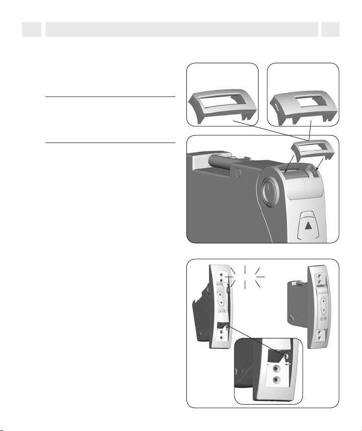
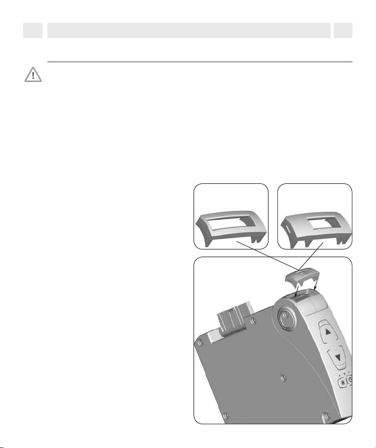
Den erforderlichen Gurtbandein-
3.
lauf einsetzen.
So gewährleisten Sie den korrekten
Lauf des jeweiligen Gurtbandes.
WICHTIG
Der Gurtbandeinlauf muss vor
dem Montagerahmen eingesetzt
werden.
Den Montagerahmen aufstecken
4.
und einrasten lassen.
Gurtbandeinlauf für:
Standardgurtband
23 mm
Klick
Minigurtband
15 mm
14
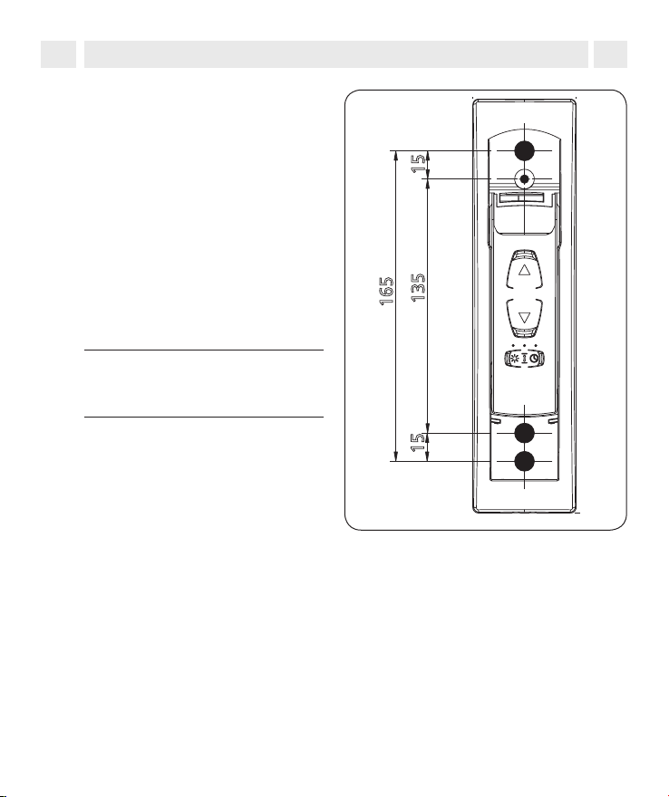
113
36.7
117
55
220
135
165
15
15
9. Unterputzmontage
i
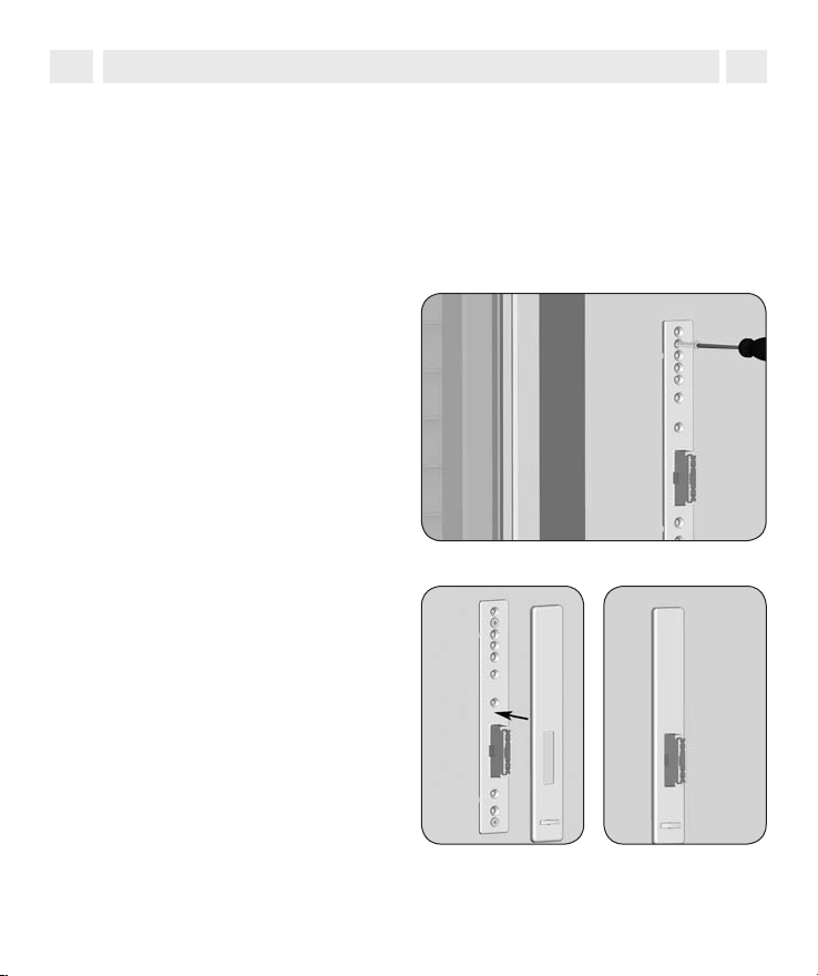
Vorhandene Montagelöcher ver-
5.
wenden.
Zur Befestigung des Gurtwicklers
benötigen Sie zwei Montagelöcher.
In der Regel können Sie die vorhandenen Montagelöcher verwenden,
um den Gurtwickler festzuschrauben.
Falls nicht, schieben Sie den Gurtwickler in den Gurtkasten und
zeichnen Sie die erforderlichen
Montagelöcher an, sonst weiter
mit Punkt 7.
HINWEIS
Beachten Sie die Lochabstände für
das Unterputzgerät.
Montagelöcher bohren
6.
(falls erforderlich).
Ziehen Sie anschließend den Gurtwickler wieder aus dem Gurtkasten
und bohren Sie die Montagelöcher
mit einem 6 mm Steinbohrer. Stecken Sie danach die beiliegenden
Montagedübel in die Bohrlöcher.
D
15
9. Unterputzmontage
i
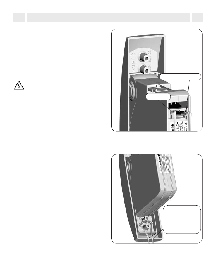
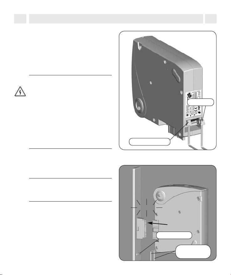
Das Netzteil und den
7.
Sonnensensor anschließen.
Schließen Sie jetzt das Netzteil
und, wenn gewünscht, den Sonnensensor auf der Rückseite des
Gurtwicklers an.
D
ACHTUNG
Der falsche Anschluss der Stecker
kann zur Zerstörung des Gurtwicklers führen.
◆ Stecken Sie beiden Stecker sei-
tenrichtig in die Öffnung. Beachten Sie dazu die Anschlusssymbole auf dem Typenschild.
◆ Stecken Sie die Stecker niemals
mit Gewalt auf die Platine.
Anschlussleitungen sicher
8.
verlegen.
Verlegen Sie die Anschlussleitungen
wie im Bild gezeigt, auf der Geräterückseite und führen Sie beide Leitungen durch die Einkerbungen im
Montagerahmen.
Sonnensensor
Netzteil
Die Leitungen
durch die
Einkerbungen
führen.
16
9. Unterputzmontage
i
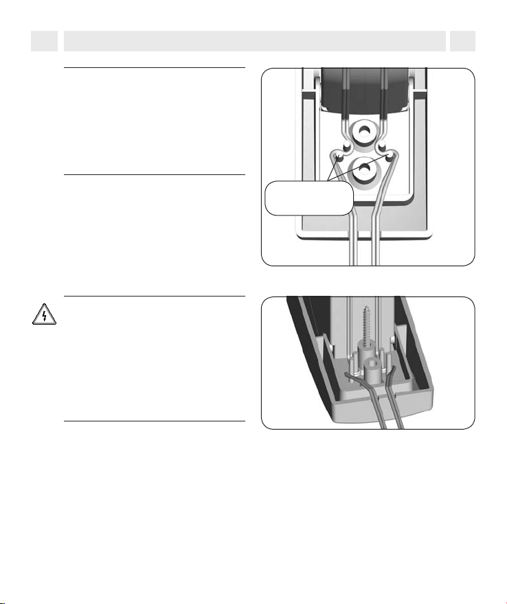
8.
WICHTIG
Zugentlastung einhalten. Verlegen
Sie beide Anschlussleitungen unbedingt mit Zugentlastung, damit Sie
nach der Montage nicht mehr aus
dem Gerät herausgezogen werden
können.
Beschädigte Kabel können zu
Fehlfunktionen führen.
Achten Sie auf eine sichere Verlegung. Die Anschlussleitungen
dürfen beim Anschrauben des
Gurtwicklers nicht gequetscht
oder durch die Montageschrauben
beschädigt werden.
D
Zugentlastung
einhalten
17
9. Unterputzmontage
i
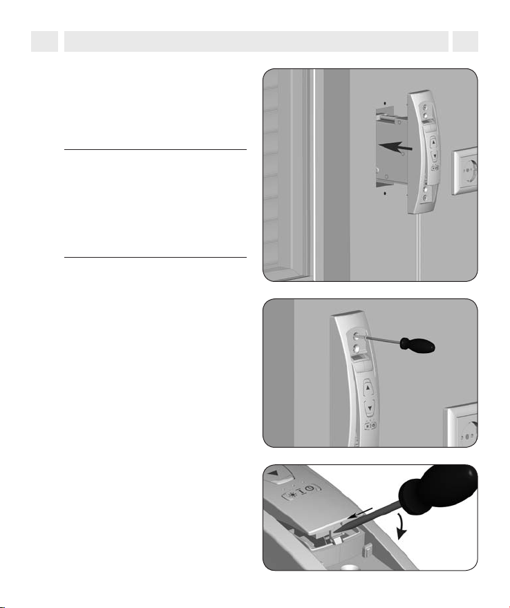
Den Gurtwickler festschrauben.
9.
Schieben Sie den Gurtwickler in den
Gurtkasten und schrauben Sie ihn
mit den beiliegenden Montageschrauben fest.
WICHTIG
Achten Sie auf die Anschlussleitungen. Führen Sie beide Anschlussleitungen an der Unterseite des Gurtwicklers durch die Einkerbungen
des Montagerahmens, wie auf Seite
16 beschrieben.
D
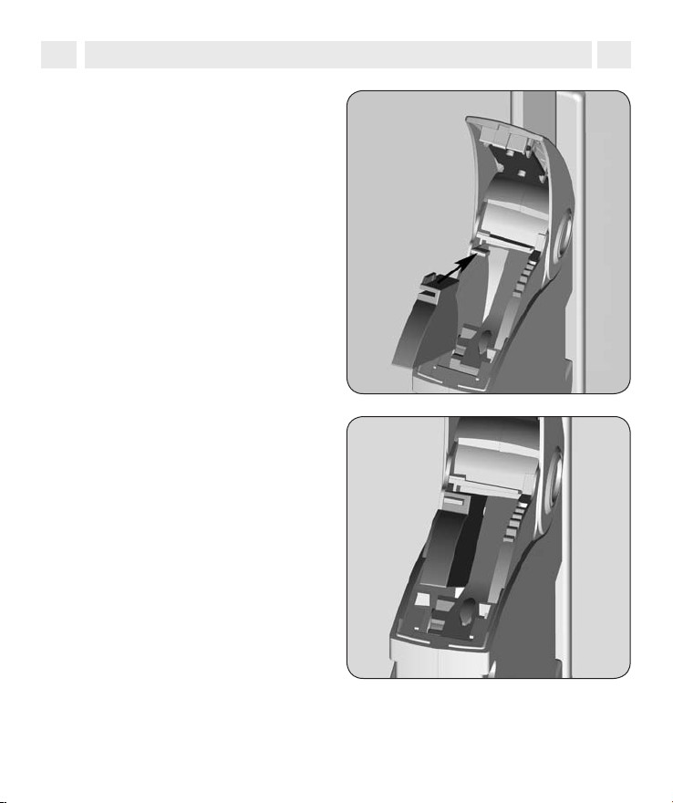
Das Bedienfeld öffnen.
10.
Durch Drücken und Hebeln mit
einem flachen Schraubendreher
können Sie das Bedienfeld öffnen.
18
9. Unterputzmontage
i
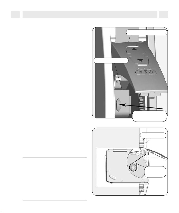
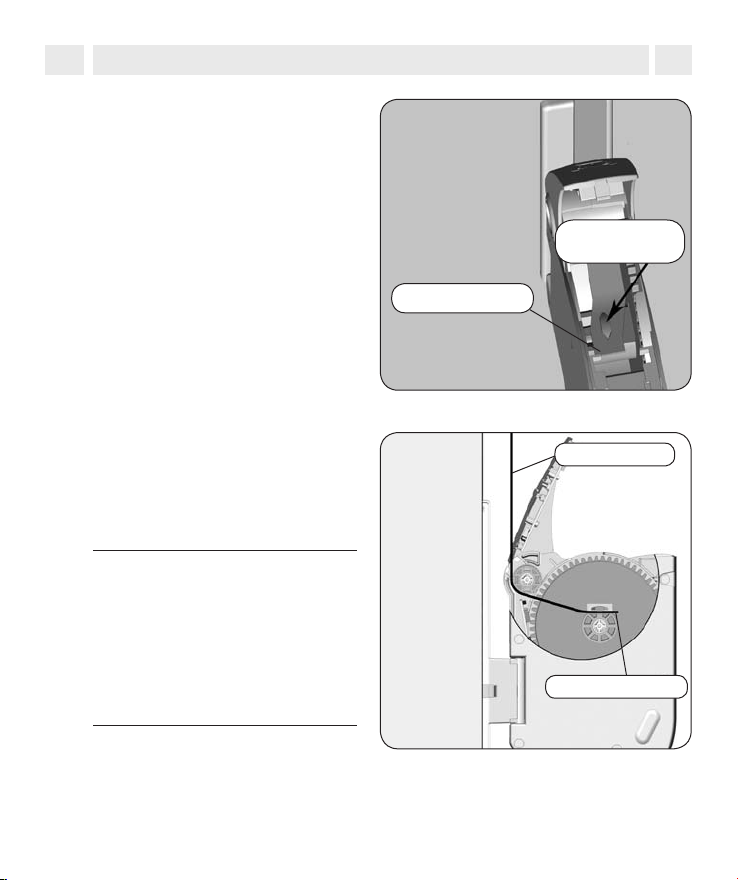
Das Gurtband einführen.
11.
Führen Sie das Gurtband von oben
in den Gurtwickler ein.
Das Gurtband über den Befesti-
12.
gungshaken ziehen.
Führen Sie das Gurtband im Gerät
weiter, wie unten in der Schnittdarstellung gezeigt und schieben Sie
anschließend das Gurtband von
unten über den Befestigungshaken.
Gurtbandverlauf bei
Unterputzmontage.
Diese Schnittdarstellung zeigt den
Verlauf des Gurtbandes innerhalb
des Gurtwicklers.
D
Gurtbandeinlauf
Gurtbandende
Befestigungs-
haken
Gurtband
HINWEIS
Falls der Befestigungshaken nicht
zugänglich ist, müssen Sie das Netzteil in die Netzsteckdose stecken
und mit den Bedientasten den Haken in die richtige Position fahren.
Ziehen Sie anschließend das Netzteil wieder aus der Netzsteckdose.
Gurtband-
ende
19
9. Unterputzmontage
i
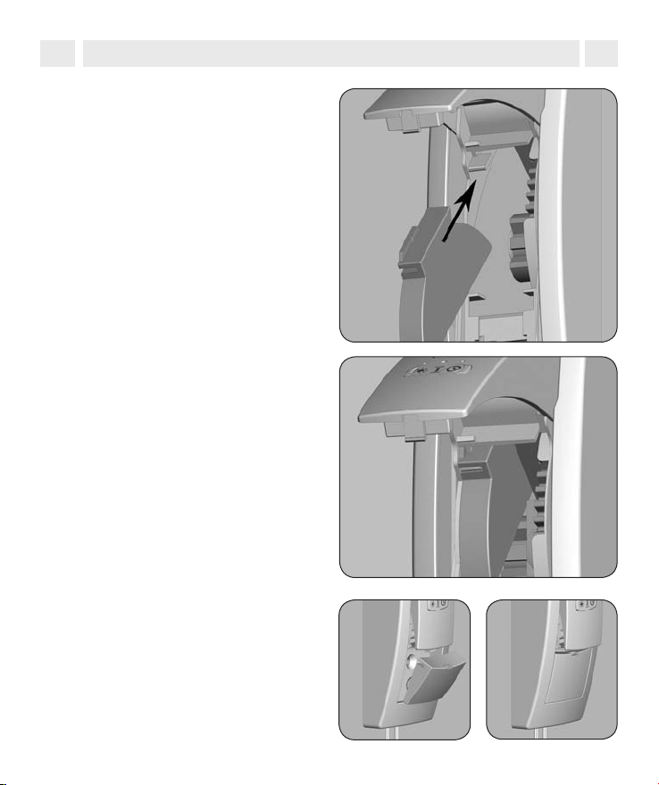
Optional, den Gurtbandadapter
13.
montieren.
Nur bei Minigurtband (15 mm
Breite) erforderlich, sonst weiter
mit Punkt 14. Um eine optimale
Gurtführung für Minigurtbänder zu
erreichen, müssen Sie nach dem
Einführen des Gurtbandes den beiliegenden Gurtbandadapter in das
Wickelradfach schieben.
D
Die Schraubenabdeckung
14.
aufstecken.
Drücken Sie die untere Schraubenabdeckung in den Montagerahmen und schließen Sie das
Wickelradfach durch Zudrücken des
Bedienfeldes.
20
9. Unterputzmontage
i
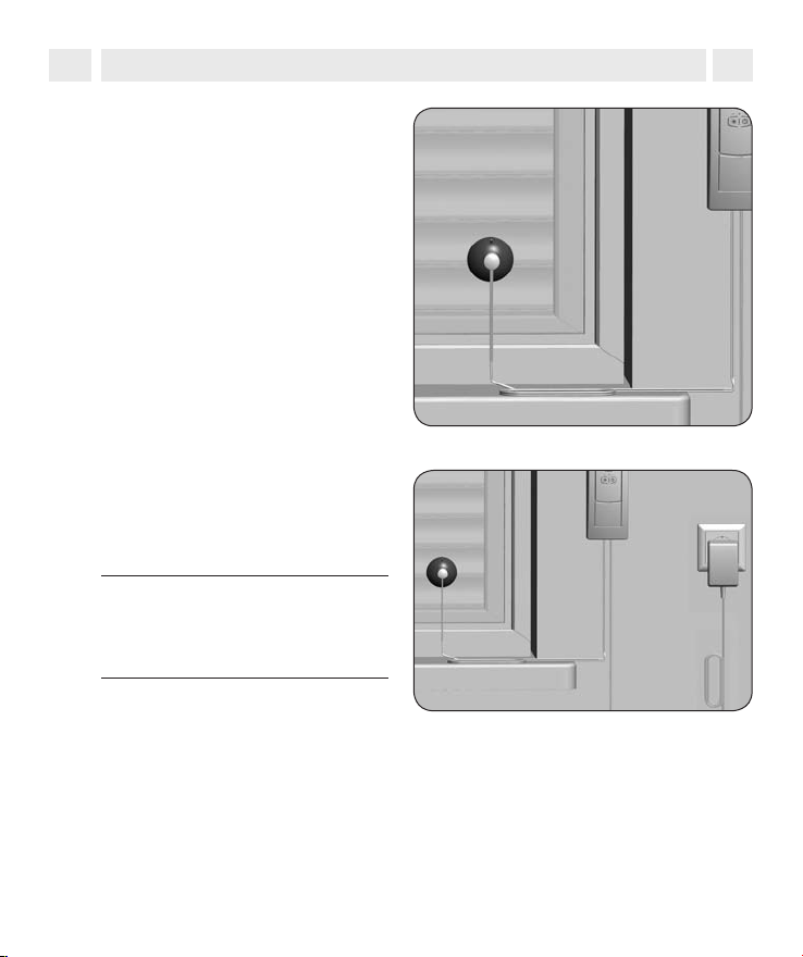
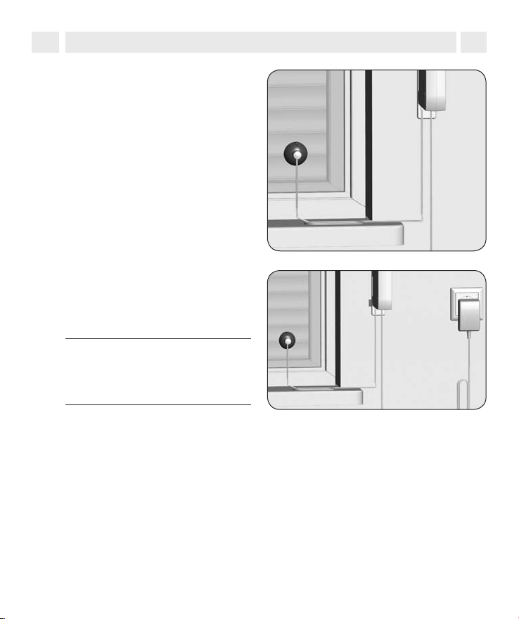
Den Sonnensensor montieren.
15.
Befestigen Sie den Sonnensensor
mit dem Saugnapf an der Fensterscheibe. Die Position des Sonnensensors an der Fensterscheibe legt
fest, bis wohin sich der Rollladen bei
Sonneneinfall schließen soll.
Inbetriebnahme.
16.
Stecken sie das Netzteil in die 230 V
Netzsteckdose. Die Montage ist
damit abgeschlossen.
WICHTIG
Die Netzsteckdose und das Netzteil müssen immer frei zugänglich
sein.
D
Weiter mit den Einstellungen ab
17.
Kapitel 11, s. Seite 30.
21

10. Aufputzmontage
i
Den alten Gurtwickler ausbauen,
1.
falls Sie eine bestehende Rollladenanlage umrüsten.
◆ Lassen Sie den Rollladen ganz
herunter, bis die Lamellen vollständig geschlossen sind.
◆ Bauen Sie den alten Gurtwick-
ler aus und wickeln Sie das
Gurtband ab.
Es besteht Verletzungsgefahr
durch die vorgespannte Feder im
alten Gurtwickler.
Die Federdose kann beim Herausnehmen unko ntrolliert zurückschnellen. Halten Sie die Federdose
beim Lösen des Gurtbandes gut
fest und lassen Sie sie langsam
zurückdrehen, bis die Federdose
vollständig entspannt ist.
Das Gurtband vorbereiten.
2.
◆ Schneiden Sie das Gurtband ca.
20 cm unterhalb des Gurtkastens ab.
◆ Schlagen Sie das Ende des Gurt-
bandes ca. 2 cm um und schneiden Sie in die Mitte einen kurzen
Schlitz. So können Sie später das
Band auf dem Wickelrad einhaken.
D
20 cm
22
10. Aufputzmontage
i
Montage auf Fensterrahmen etc.
Schwache Fensterrahmen können ausbrechen
◆ Prüfen Sie bei Montage auf Fensterrahmen deren Aufbau und Belastbarkeit.
Gerade bei Montage auf Kunststoonstruktionen müssen die Befestigungsschrauben fest sitzen und dürfen sich während des Betriebes nicht lösen.
◆ Fragen Sie ggf. Ihren Fensterhersteller, bevor Sie den Gurtwickler auf einem
Fensterrahmen aus Kunststoff befestigen.
D
Den erforderlichen Gurtband-
3.
einlauf einsetzen.
So gewährleisten Sie den korrekten
Lauf des jeweiligen Gurtbandes.
Vorhandene Montagelöcher
4.
verwenden.
Zur Befestigung des Gurtwicklers
benötigen Sie zwei Montagelöcher.
In der Regel können Sie die vorhandenen Montagelöcher verwenden,
um den Wandhalter festzuschrauben. Falls nicht, zeichnen Sie die erforderlichen Montagelöcher neu an.
Gurtbandeinlauf für:
Standardgurtband
23 mm
Minigurtband
15 mm
23
10. Aufputzmontage
i
Montagelöcher bohren
5.
(falls erforderlich).
Bohren Sie anschließend die Montagelöcher mit einem 6 mm Steinbohrer und stecken Sie die beiliegenden
Montagedübel in die Bohrlöcher.
Den Wandhalter festschrauben.
6.
Schrauben Sie danach den Wandhalter mit den beiliegenden Schrauben fest.
Die Wandhalterblende auf den
7.
Wandhalter schieben.
D
24
10. Aufputzmontage
i
Das Netzteil und den Sonnensen-
8.
sor anschließen.
Schließen Sie jetzt das Netzteil
und, wenn gewünscht, den Sonnensensor auf der Rückseite des
Gurtwicklers an.
ACHTUNG
Der falsche Anschluss der Stecker
kann zur Zerstörung des Gurtwicklers führen.
◆ Stecken Sie beiden Stecker sei-
tenrichtig in die Öffnung. Beachten Sie dazu die Anschlusssymbole auf dem Typenschild.
◆ Stecken Sie die Stecker niemals
mit Gewalt auf die Platine.
Den Gurtwickler anschließend in
9.
die Wandhalterung drücken.
WICHTIG
Führen Sie die Anschlussleitungen
hinter den Kabelhalter.
D
Netzteil
Sonnensensor
Klick
Kabelhalter
Anschluss-
leitungen
25

10. Aufputzmontage
i
Drücken Sie die beiliegenden
10.
Schraubenkappen auf die
Gehäuseschrauben.
Das Bedienfeld öffnen.
11.
Durch Drücken und Hebeln mit
einem flachen Schraubendreher
können Sie das Bedienfeld öffnen.
Führen Sie das Gurtband von oben
12.
in den Gurtwickler ein.
D
26
Gurtbandeinlauf
10. Aufputzmontage
i
Das Gurtband über den
13.
Befestigungshaken ziehen.
Führen Sie das Gurtband im Gerät
weiter, wie unten in der Schnittdarstellung gezeigt, und schieben Sie
anschließend das Gurtband von
oben über den Befestigungshaken.
Gurtbandverlauf bei
14.
Aufputzmontage.
Diese Schnittdarstellung zeigt den
Verlauf des Gurtbandes innerhalb
des Gurtwicklers.
HINWEIS
Falls der Befestigungshaken nicht
zugänglich ist, müssen Sie das Netzteil in die Netzsteckdose stecken
und mit den Bedientasten den Haken in die richtige Position fahren.
Ziehen Sie anschließend das Netzteil wieder aus der Netzsteckdose.
D
Befestigungs-
haken
Gurtbandende
Gurtband
Gurtbandende
27
10. Aufputzmontage
i
Optional den Gurtbandadapter
15.
montieren.
Nur bei Minigurtband (15 mm Breite)
erforderlich, sonst weiter mit Punkt
16. Um eine optimale Gurtführung
für Minigurtbänder zu erreichen,
müssen Sie nach dem Einführen
des Gurtbandes den beiliegenden
Gurtbandadapter in das Wickelradfach schieben.
D
28
10. Aufputzmontage
i
Den Sonnensensor
16.
montieren.
Befestigen Sie den Sonnensensor
mit dem Saugnapf an der Fensterscheibe. Die Position des Sonnensensors an der Fensterscheibe legt
fest, bis wohin sich der Rollladen bei
Sonneneinfall schließen soll.
Inbetriebnahme
17.
Das Netzteil in die 230 V Netzsteckdose stecken. Die Montage ist
damit abgeschlossen.
WICHTIG
Die Netzsteckdose und das Netzteil müssen immer frei zugänglich
sein.
D
29

11. Drehrichtung prüfen und korrigieren
i
HINWEIS
Je nach Montageart (Unterputz-/Aufputzmontage) muss die Drehrichtung
unterschiedlich gewählt werden. Die Drehrichtung ist ab Werk für die Unterputzmontage eingestellt und muss für den Fall einer Aufputzmontage korrigiert
werden.
Bitte überprüfen Sie vor allen weiteren Einstellungen die Drehrichtung wie folgt:
kurz drücken, das Gurtband muss in den Gurtwickler laufen.
kurz drücken, das Gurtband muss aus dem Gurtwickler herauslaufen.
Falls die Drehrichtung korrekt ist, fahren Sie bitte mit Kapitel 12 fort.
Drehrichtung korrigieren
D
Die SET-Taste 10 Sekunden lang
1.
mit Hilfe eines spitzen Gegenstandes (z. B. mit einer Büroklammer)
drücken.
Beachten Sie die
2.
Kontrollleuchten
◆ Die Uhr-Kontrollleuchte
blinkt: = Aufputzmontage
◆ Durch nochmaliges Drücken
wechseln Sie die Drehrichtung
erneut.
◆ Die Sonnen-Kontrollleuchte
blinkt : = Unterputzmontage
30
Beachten Sie, dass die SET-Taste
über dem Pfeilsymbol liegt.
Sonnen-
Kontrollleuchte
Uhr-
Kontrollleuchte

12. Endpunkte einstellen
i
WICHTIG
Damit der Rollladen oben und unten an der von Ihnen gewünschten Stelle
stehenbleibt, müssen die Endpunkte eingestellt werden. Sie müssen unbedingt
beide Endpunkte einstellen, sonst kann es zu Funktionsstörungen kommen.
Ohne Endpunkteinstellung läuft der Gurtwickler nur solange, wie eine der beiden
Bedientasten gedrückt wird.
Den oberen Endpunkt einstellen
Die Tasten gleichzeitig drücken
1.
und festhalten.
Die SET-Taste mit Hilfe eines spitzen Gegenstandes (z.B. mit einer
Büroklammer) drücken.
Der Rollladen fährt hoch und die
Uhr-Kontrollleuchte blinkt.
HINWEIS
Straffen Sie das Gurtband etwas,
bis es durch das Rollladengewicht
gespannt wird.
+
Die SET-Taste liegt über
dem Pfeilsymbol.
Uhr-
Kontrollleuchte
D
Die Tasten loslassen...,
2.
...sobald der Rollladen die gewünschte Position für den oberen Endpunkt
erreicht hat. Der Rollladen stoppt,
der obere Endpunkt ist gespeichert.
WICHTIG
s. nächste Seite
+
31

12. Endpunkte einstellen
i
2.
WICHTIG
Stellen Sie den oberen Endpunkt
nicht ganz bis zum Anschlag ein.
Lassen Sie die Tasten rechtzeitig
los und fahren Sie nicht über den
jeweiligen Endpunkt hinaus. Es
kann sonst zur Überlastung bzw.
Zerstörung des Rollladens und/oder
des Motors führen.
Den unteren Endpunkt einstellen
Die Tasten gleichzeitig drücken
3.
und festhalten.
Der Rollladen fährt herunter.
Die Tasten loslassen...,
4.
...sobald der Rollladen die gewünschte Position für den unteren Endpunkt
erreicht hat. Der Rollladen stoppt,
der untere Endpunkt ist gespeichert.
WICHTIG
Achten Sei beim Einstellen des
unteren Endpunktes darauf, dass
das Gurtband beim Erreichen des
Endpunktes nicht zu schlaff wird.
D
+
+
32

12. Endpunkte einstellen
i
Endpunkte verändern bzw. korrigieren
Fahren Sie den Rollladen in die
5.
Mittelstellung und stellen Sie den
jeweiligen Endpunkt neu ein.
HINWEIS
Nach einiger Zeit müssen Sie eventuell die Endpunkte neu einstellen,
da es im laufenden Betrieb zu einer
Verlängerung des Gurtbandes kommen kann.
13. Manuelle Bedienung
i
Die Bedienung von Hand ist in jeder Betriebsart möglich und hat
Vorrang vor den programmierten
Automatikfunktionen.
HINWEIS
◆ Bei der manuellen Bedienung
bleiben die Endpunkteinstellungen erhalten.
◆ Sie können den Gurtwickler
max. 5 Minuten mit maximaler
Last betreiben, lassen Sie danach den Antrieb ca. 30 Minuten abkühlen.
oder
D
Bedien-
tasten
33

13.1 Den Gurtwickler bedienen
i
Den Rollladen öffnen.
1.
Der Rollladen fährt durch kurzen
Tastendruck bis zum oberen Endpunkt.
Den Rollladen zwischenzeitlich
2.
stoppen.
Eine beliebige Taste kurz drücken.
Den Rollladen schließen.
3.
Der Rollladen fährt durch kurzen
Tastendruck bis zum unteren Endpunkt.
14. Automatikbetrieb; Öffnungs- und Schließzeit einstellen
i
Gleiche Schaltzeiten für alle Tage
Sie können am Gurtwickler je eine Öffnungs- und Schließzeit einstellen, die an
allen Tagen gilt. Beim Erreichen dieser Zeit öffnet oder schließt sich Ihr Rollladen
automatisch.
Verändern der Schaltzeiten
Sie können die Schaltzeiten jederzeit verändern. Beachten Sie, dass jedes neue
Speichern die alten Einstellungen löscht.
HINWEIS
◆ Zur Einstellung der Schaltzeiten müssen Sie diesen Schritt einmalig zu der
Zeit vornehmen, zu der sich Ihr Rollladen öffnen oder schließen soll. Zum
Beispiel um 8:00 Uhr morgens, wenn der Rollladen jeden Morgen um 8:00
Uhr öffnen soll.
◆ Sie müssen mindestens eine Schaltzeit einstellen, damit der Automatik-
betrieb aktiv wird.
◆ Wenn Sie die Öffnungs- und/oder Schließzeit einstellen bzw. verändern,
werden Ihre Einstellungen erst am nächsten Tag ausgeführt.
oder oder oder
D
34

14. Automatikbetrieb; Öffnungs- und Schließzeit einstellen
i
Eine Öffnungszeit (▲) einstellen (z.B. um 8:00 Uhr morgens)
Die Tasten gleichzeitig kurz
1.
drücken.
Die Uhr-Kontrollleuchte blinkt ...
2.
...und der Rollladen fährt nach oben.
Der Automatikbetrieb ist jetzt eingeschaltet. Ihr Rollladen öffnet sich
jeden Morgen automatisch um
8:00 Uhr.
Eine Schließzeit (▼) einstellen (z.B. um 20:30 Uhr abends)
Die Tasten gleichzeitig kurz
1.
drücken.
Die Uhr-Kontrollleuchte blinkt ....
2.
...und der Rollladen fährt nach unten. Der Automatikbetrieb ist jetzt
eingeschaltet. Ihr Rollladen schließt
sich jeden Abend automatisch um
20:30 Uhr.
+
Uhr-Kontrollleuchte
+
Uhr-Kontrollleuchte
D
35

15. Automatikbetrieb; Auto/Manu - Umschaltung
i
Bei Bedarf kann jederzeit zwischen Automatikbetrieb und manueller Steuerung
umgeschaltet werden.
HINWEIS
Eine manuelle Bedienung des Rollladens ist zu jeder Zeit unabhängig von der
Automatik möglich.
D
Die Taste ca. 1 Sekunde drücken.
1.
Beachten Sie die
2.
Uhr-Kontrollleuchte.
AUS
Automatikbetrieb AUS
Die zuvor eingestellten
Schaltzeiten bleiben
gespeichert.
EIN
Automatikbetrieb EIN
Blinkend
Nach vorherigem Netzaus fall, wenn zuvor mindes tens eine Schaltzeit ein gestellt wurde.
HINWEIS
Nach einem Netzausfall
verschieben sich die Schaltzeiten um die Dauer des
Netzausfalls nach hinten
und müssen ggf. neu eingestellt werden.
Uhr- Kontrollleuchte
36

16. Sonnenautomatik
i
Die Sonnenautomatik ermöglicht
Ihnen, zusammen mit dem Sonnensensor, die helligkeitsabhängige
Steuerung Ihrer Rollläden. Dazu
wird der Sonnensensor mit einem
Saugnapf an der Fensterscheibe
befestigt und über einen Stecker mit
dem Gurtwickler verbunden, s. Seite
16 und Seite 25.
Funktion der Sonnenautomatik
Automatischer Tieflauf
Erkennt der Sensor 10 Minuten lang
ununterbrochen Sonne, senkt sich
der Rollladen, bis sein Schatten den
Sonnensensor bedeckt.
D
Beispiel für die
Aufputzmontage
10 Min.
Sonne
37

16. Sonnenautomatik
i
Automatisches Freiziehen
Nach ca. 20 Minuten fährt der Rollladen automatisch ein Stück hoch,
um den Sensor freizugeben. Bei
weiterer Sonneneinstrahlung bleibt
der Rollladen in dieser Position
stehen. Fällt die Helligkeit unter
den eingestellten Grenzwert, fährt
er bis zum oberen Endpunkt zurück.
HINWEIS
Bei wechselnden Wetterbedingungen können die Verzögerungszeiten
von 10 und 20 Minuten überschritten werden.
16.1 Sonnenautomatik ein-/ausschalten
i
Durch wiederholtes kurzes Drü-
1.
cken wird die Sonnenautomatik
ein- bzw. ausgeschaltet.
Beachten Sie die
2.
Sonnen-Kontrollleuchte.
AUS
Sonnenautomatik AUS
EIN
Sonnenautomatik EIN
Blinkend
Grenzwert überschritt en, blinkt die Sonnen Kontrollleuchte. Die Son nenautomatik ist aktiv.
Wir d der eingestellt e
D
Nach
20 Min.
Sonnen-Kontrollleuchte
38

16.2 Sonnenautomatik: Grenzwert einstellen
i
Durch Einstellen oder Verändern des Grenzwertes wird die Sonnenautomatik
eingeschaltet.
Aktuelle Helligkeit als Grenzwert übernehmen und die
Sonnenautomatik einschalten.
Die Tasten gleichzeitig drücken.
1.
Die aktuelle Helligkeit gilt jetzt
2.
als Grenzwert.
Wird dieser Wert überschritten,
fährt der Rollladen nach unten bis
zum Sonnensensor.
HINWEIS
Liegt bei der Einstellung des Grenzwertes der aktuelle Helligkeitswert
außerhalb des Messbereichs, blinkt
die Sonnen-Kontrollleuchte kurz
auf und der Grenzwert wird auf die
Messbereichsgrenze gesetzt.
+
Sonnen-Kontrollleuchte
D
39

17. Einstellungen löschen
i
Bei Bedarf können Sie alle Einstellungen löschen und die Werkseinstellung
wieder herstellen.
Die Tasten 4 Sekunden
1.
gleichzeitig drücken.
Die Tasten loslassen...,
2.
... danach sind alle Einstellungen
gelöscht.
◆ Endpunkte
◆ Schaltzeiten
◆ Sonnenautomatik
Zur Quittierung blinken beide
3.
Kontrollleuchten.
HINWEIS
Die Drehrichtung bleibt erhalten.
+ +
+ +
D
40

18. Den Unterputz-Gurtwickler ausbauen (z. B. bei Umzug)
i
Alle Einstellungen löschen.
1.
Den Rollladen vollständig schlie-
2.
ßen. Die Taste drücken und halten.
Ziehen Sie dabei das Gurtband
3.
soweit wie möglich oben aus dem
Gurtwickler heraus.
Es besteht Verletzungsgefahr
durch das Wickelrad.
Fassen Sie nicht bei laufendem Motor in das Wickelradfach. Ziehen Sie
immer den Netzstecker, bevor Sie in
das Wickelradfach fassen.
Ziehen Sie das Netzteil aus der
4.
Steckdose, öffnen Sie das Bedienfeld und lösen Sie das Gurtband
vom Befestigungshaken.
Ziehen Sie es vollständig heraus
und demontieren Sie danach den
Gurtwickler.
+ +
D
Lösen Sie zum Schluss beide Ste-
5.
cker auf der Rückseite des Gerätes
mit einem kleinen Schraubendreher und demontieren Sie den
Sonnensensor.
41

19. UP-Gurtwickler, das Gurtband bei Geräteausfall entfernen
i
Sollte der Gurtwickler einmal ausfallen und der Motor nicht mehr
laufen, können Sie mit Hilfe der
Getriebeentriegelung das Gurtband
vollständig aus dem Gurtwickler
ziehen, ohne es zerschneiden zu
müssen. Dazu müssen Sie zuerst
den Unterputz-Gurtwickler demontieren.
Ziehen Sie das Netzteil aus der
1.
Steckdose.
Entriegeln Sie das Getriebe mit
2.
Hilfe eines spitzen Gegenstandes
(z.B. mit einer Büroklammer).
ACHTUNG
Halten Sie das Gurtband fest, da
der Rollladen sonst ungebremst
herunterfallen kann.
Beim Drücken müssen Sie einen
kleinen Widerstand überwinden.
Getriebe-
entriegelung
D
Getriebe-
entriegelung
Halten Sie die Getriebeentriege-
3.
lung gedrückt und ziehen Sie anschließend das Gurtband soweit
wie möglich aus dem Gurtwickler
heraus.
Lösen Sie das Gurtband vom Befestigungshaken und ziehen Sie es
vollständig aus dem Gurtwickler.
42

20. Den Aufputz-Gurtwickler ausbauen (z. B. bei Umzug)
i
Alle Einstellungen löschen.
1.
Den Rollladen vollständig schlie-
2.
ßen. Die Taste drücken und halten.
Ziehen Sie dabei das Gurtband
3.
soweit wie möglich oben aus dem
Gurtwickler heraus.
Es besteht Verletzungsgefahr
durch das Wickelrad.
Fassen Sie nicht bei laufendem Motor in das Wickelradfach. Ziehen Sie
immer den Netzstecker, bevor Sie in
das Wickelradfach fassen.
Ziehen Sie das Netzteil aus der
4.
Steckdose, öffnen Sie das Bedienfeld und lösen Sie das Gurtband
vom Befestigungshaken.
Ziehen Sie es vollständig heraus.
Lösen Sie danach den Gurtwickler
5.
vom Wandhalter.
Lösen Sie zum Schluss beide Ste-
6.
cker auf der Rückseite des Gerätes
mit einem kleinen Schraubendreher und demontieren Sie den
Sonnensensor.
+ +
D
43

21. AP-Gurtwickler, das Gurtband bei Geräteausfall entfernen
i
Sollte der Gurtwickler einmal ausfallen und der Motor nicht mehr
laufen, können Sie mit Hilfe der
Getriebeentriegelung das Gurtband
vollständig aus dem Gurtwickler
ziehen, ohne es zerschneiden zu
müssen. Dazu müssen Sie zuerst
den Aufputz-Gurtwickler demontieren.
Ziehen Sie das Netzteil aus der
1.
Steckdose.
Entriegeln Sie das Getriebe mit
2.
Hilfe eines spitzen Gegenstandes
(z.B. mit einer Büroklammer).
ACHTUNG
Halten Sie das Gurtband fest, da
der Rollladen sonst ungebremst
herunterfallen kann.
Beim Drücken müssen Sie einen
kleinen Widerstand überwinden.
Halten Sie die Getriebeentrie-
3.
gelung gedrückt und ziehen Sie
anschließend das Gurtband soweit
wie möglich aus dem Gurtwickler
heraus.
Lösen Sie das Gurtband vom Befestigungshaken und ziehen Sie es
vollständig aus dem Gurtwickler
D
Getriebe-
entriegelung
Getriebe-
entriegelung
Demontieren Sie zuletzt den Auf-
4.
putz-Gurtwickler wie zuvor auf
Seite 43 gezeigt.
44

22. Was tun, wenn... ?
i
D
Störung
...der Gurtwickler keine Funktion
zeigt?
... der Gurtwickler zur eingestellten
Schaltzeit nicht reagiert?
...die Uhr-Kontrollleuchte blinkt?
...der Rollladen nicht mehr ganz
hoch läuft?
... der Rollladen stehen bleibt sobald
die Bedientaste losgelassen wird?
... die Sonnenfunktion nicht
reagiert?
Ursache / Lösung
Überprüfen Sie die Stromversorgung inkl.
Anschlusskabel und Anschlussstecker.
Eventuell hat es einen Netzausfall gegeben, stellen Sie die Schaltzeiten neu ein,
s. Seite 34.
Eventuell hat es einen Netzausfall gegeben, stellen Sie die Schaltzeiten neu ein,
s. Seite 34.
Möglicherweise haben sich die Endpunkte
durch die Banddehnung verstellt. Stellen
Sie die Endpunkte neu ein, s. Seite 31.
Die Endpunkte sind noch nicht eingestellt,
stellen Sie die Endpunkte ein, s. Seite 31.
a) Prüfen Sie ob der Sonnensensor noch
an der Fensterscheibe klebt.
b) Ist eventuell das Sonnenlicht nicht hell
genug oder durch Schattenbildung zu
stark abgedunkelt?
c) Überprüfen Sie die Sonnen-Kontroll leuchte, diese muss leuchten, s. Seite
38.
d) Überprüfen Sie das Anschlusskabel des
Sonnensensors auf Beschädigung.
e) Steckt der Stecker richtig im Gerät?
45

22. Was tun, wenn... ?
i
D
Störung
... der Rollladen im Tieflauf stehen
bleibt?
... der Rollladen im Hochlauf plötzlich stehen bleibt?
... der Gurtwickler sich weder Auf-
noch Abfahren lässt?
Ursache / Lösung
a) Der Rollladen ist eventuell auf ein Hin derniss gelaufen.
Fahren Sie den Rollladen wieder hoch
und entfernen Sie das Hindernis.
b) Der Rollladen ist möglicherweise zu
leicht.
Beschweren Sie den Rollladen in dem
Sie z. B. in die unterste Lamelle ein
Flacheisen einschieben.
a) Der Antrieb ist blockiert, z. B. durch
Festfrieren des Rollladens oder ande re Hindernisse.
b) Eventuell ist der Rollladen nicht leicht gängig genug. Überprüfen Sie den
Rollladen bzw. die Rollladenführung.
c) Der Rollladen ist möglicherweise zu
schwer. Die maximale Zugkraft des
Gurtwicklers wurde überschritten,
s. Seite 47.
Die max. Laufzeit des Antriebs wurde
überschritten, s. Seite 33 und Seite 47.
Der Motor ist zu heiß.
Nach ca. 30 Minuten ist der Gurtwickler
wieder betriebsbereit.
46

23. Technische Daten
i
Betriebsspannung Netzteil: 230 V / 50 Hz
Leistung Stand-by: 1,35 W
Netzteil: 24 V DC / 29 W
Drehmoment: MdN = 2,8 Nm
Max. Drehzahl: 34 U/min.
Endzugkraft: 7 kg
Max. Zugkraft / Anfangszugkraft: 25 kg
Kurzzeitbetrieb: 5 Minuten
Schutzklasse: III
Schutzart: IP20 (Nur für trockene Räume)
Positioniergenauigkeit: 5 mm
Anzahl der Schaltzeiten: 2 (AUF und AB)
Einstellbereich Sonnenautomatik: 2.000 bis 20.000 Lux
Umgebungstemperatur: 0 - 40 °C
Abmessungen: s. Seite 48 / 49
Zulässige Gurtbandbreiten: 15 mm (Minigurtband)
23 mm (Gurtband)
Gurtlängen:
15 mm (Minigurtband) 5,5 m bei 1,0 mm Gurtstärke
23 mm (Standardgurtband) 5,5 m bei 1,0 mm Gurtstärke
4,5 m bei 1,3 mm Gurtstärke
D
Die EG-Konformität wurde nachgewiesen
Einhaltung der europäischen Niederspannungsrichtlinie 2006/95/EG, EMVRichtlinie 2004/108/EG, konform mit EN 60335-1, EN 60335-2-97, EN 55 014-1,
EN 55 014-2, IEC 61558-2-6, IEC 61558-1 (Netzteil).
47

55
165
23.1 Abmessungen Unterputzgerät
i
D
15
135
15
Alle Angaben in mm.
220
117
34.5
113
1
36.7
48

37.5
23.2 Abmessungen Aufputzgerät
i
D
34.5
Alle Angaben in mm.
205
149.7
135.7
49

24. Garantiebedingungen
i
Die superrollo Hausautomatisierung GmbH gibt 24 Monate Garantie für Neugeräte,
die entsprechend der Einbauanleitung montiert wurden. Von der Garantie abgedeckt
sind alle Konstruktionsfehler, Materialfehler und Fabrikationsfehler.
Ausgenommen von der Garantie sind:
◆ Fehlerhafter Einbau oder Installation
◆ Nichtbeachtung der Einbau- und Bedienungsanleitung
◆ Unsachgemäße Bedienung oder Beanspruchung
◆ Äußere Einwirkungen wie Stöße, Schläge oder Witterung
◆ Reparaturen und Abänderungen von dritten, nicht autorisierten Stellen
◆ Verwendung ungeeigneter Zubehörteile
◆ Schäden durch unzulässige Überspannungen (z.B. Blitzeinschlag)
◆ Funktionsstörungen durch Funkfrequenzüberlagerungen und sonstige Funkstö-
rungen
Auftretende Mängel beseitigt die superrollo Hausautomatisierung GmbH innerhalb der
Garantiezeit kostenlos entweder durch Reparatur oder durch Ersatz der betreffenden
Teile oder durch Lieferung eines gleichwertigen oder neuen Ersatzgerätes. Durch Ersatzlieferung oder Reparatur aus Garantiegründen tritt keine generelle Verlängerung
der ursprünglichen Garantiezeit ein.
Geräte zur Reparatur bitte
senden an:
D
DPD GeoPost
superrollo Hausautomatisierung GmbH
Werrastraße 12
45768 Marl (Germany)
50
superrollo Hausautomatisierung GmbH
Gewerbepark 1
01156 Dresden (Germany)
Service-Hotline: 01803 001655 *
www.superrollo-online.de
* 9ct/Minute aus dem Festnetz der DT AG/
Mobilfunk max. 42 ct/Minute (gilt nur für
Deutschland)
Technische Änderungen, Druckfehler und Irrtümer vorbehalten. Abbildungen unverbindlich.

EN Electric roller shutter belt winder GW60
Installation and operating instructions ...........................................................51
Article no: SR10060 / SR10065
Surface-mounted installation
BA10060-2B
Flush-mounted installation

Dear customer,
i
ank you for choosing a product from our range and for the trust you have
placed in us.
Our electrical roller shutter belt winders have been designed for you in accordance with the latest technological developments and according to our high
quality standards.
Simple operation and a high level of technology have been combined in the
electric roller shutter belt winders in order to produce a high-quality product
“Made in Germany”.
EN
52

i
Contents
EN
i Dear customer, ................... 52
1. General view ........................54
2. Package contents ............... 56
3. Explanation of the safety
symbols used ......................57
4. Safety instructions .............58
5. Proper use ...........................59
6. Brief description .................... 60
7. General installation
instructions ..........................62
8. You require the following
tools 62
9. Flush-mounted
installation
10. Surface-mounted
installation ...........................72
11. Checking and correcting
the rotational direction ......80
12. Adjusting the end points .... 81
13. Manual operation ................83
13.1 Operate the
belt winder .................84
14. Automatic operation;
setting the opening and
closing times .......................84
15. Automatic operation;
Auto / Manual
switch over ..........................86
...........................63
16. Automated solar function ..87
16.1 Automated solar
functions - switching
on / off........................88
16.2. Automated solar
function: Setting
limit values .................89
17. Deleting the settings ..........90
18. Removing the flush mounted belt winder
(e.g. in the event of a
move) ................................... 91
19. Flush-mounted belt
winders, removing the
belt in the event of
unit failure ...........................92
20. Removing the surface mounted belt winder
(e.g. in the event of a
move) ................................... 93
21. Surface-mounted belt
winders, removing the
belt in the event of
unit failure ...........................94
22. What to do if... ? .................95
23. Technical specifications ......97
23.1 Dimensions
flush-mounted unit ....98
23.2 Dimensions surface-
mounted unit .............99
24. Warranty conditions .........100
53

1. General view
i
EN
Flush-mounted version
1.
5.
4.
Surface-mounted versions
6.
5.
54
1. Mounting frame
2. Operating panel
7.
2.
3. Winding wheel
compartment
8.
4. Screw cover
5. Drive release
6. Cable bushing
7. Power supply connection
8. Solar sensor connection
9. Type plate (incl. manu facturer’s specifications)
3.
9.
6.
1.
2.
3.
4.
7.
8.
9.
Legends
(Refer to page 55)
1. Wall bracket
2. Operating panel
3. Winding wheel
compartment
4. Drive release
5. Cable bracket
6. Cable bracket trim
7. Power supply connection
8. Solar sensor connection
9. Type plate (incl. manu facturer’s specifications)

1. General view
i
Flush-mounted and
surface-mounted versions
10. Belt lead-in
11. Open button
12. Close button
13. Solar button with indicator light
14. Clock setting button with
indicator light
15. SET button
EN
10.
11.
12.
13.
15.
14.
55

2. Package contents
i
EN
1.
4.
2.
3.
12.
11.
Legend
1. Power supply 230 V/50 Hz / 24 V (DC)
2. Belt inlet 23 mm
3. Belt inlet 15 mm
4. Wall bracket for surface-mounted installation, incl. panel
(not to be used for flush-mounted installation)
5. Universal belt winder
6. Belt adapter for mini belt 15 mm
7. Mounting frame for flush-mounted installation
(not to be used for surface-mounted installation)
8. Screw cover
9. Screw caps for housing screws
10. Solar sensor
11. Rawl plugs
12. Mounting screws
56
5.
10.
6.
7.
9.
8.

3. Explanation of the safety symbols used
i
Danger of fatal electric shock
is symbol indicates danger due to electrical power.
It requires that safety precautions be taken to protect life and health.
Important
STOP
safety instructions
is concerns your safety.
Adhere to all information labelled in this manner.
NOTE
is serves to draw your attention to information that is important
for trouble-free operation.
EN
57

4. Safety instructions
i
e use of defective equipment can lead to personal injury and damage to
property (electric shock, short circuits).
Never use defective or damaged equipment. Please contact our Customer
Service department in this case (see page 100).
Risk of injury due to suddenly starting
drives during installation.
Carry out all installation work with the equipment isolated from the mains.
Risk of injury due to incorrect operation.
STOP
◆ Children may not be allowed to play with the roller shutter control system.
◆ Observe the rollers during the adjustment process and ensure that all
persons are kept clear that could be harmed by sudden movement of the
roller shutter.
In accordance with EN 13659, it must be ensured that the movement specifications defined under EN 12045 are maintained. e displacement must amount to
at least 40 mm on the lower edge in the rolled-out position with a force of 150 N
in the upwards direction. In doing so, it is particularly important to ensure that
the shutter extension speed for the final 0.4 m is less than 0.2 m/s.
e power socket and power supply must be freely
accessible at all times.
EN
58

5. Proper use
i
Only use the electric roller shutter belt winder for...
... lifting and lowering roller shutters with a permissible belt.
Only use the manufacturer’s original parts.
Only use original spare parts. is will ensure that you avoid malfunctions or
damage to the unit.
e manufacturer accepts no claims for guarantee in the event that third-party
parts are used or for any resulting damage. All repairs to the eclectic roller
shutter winder must be undertaken by authorised customer service personnel.
Operating conditions
◆ Only use the electric roller shutter belt winder in dry rooms.
◆ An easily accessible 230 V/50 Hz socket must be available at the installa-
tion site.
◆ e roller shutters must lift and lower in a smooth manner. ey may not
jam.
◆ e bearing surface for the belt winder must be flat.
Permissible belts
IMPORTANT
Only use belts of permissible lengths. e insertion of longer belts can lead to
belt winder damage.
EN
Belt width Belt thickness Belt length
15 mm (mini belt) 1.0 mm 5.5 m
23 mm (standard belt) 1.0 mm 5.5 m
1.3 mm 4.5 m
59

5. Proper use
i
Permissible roller shutter area
Light plastic roller shutters up to 8 m2.
Other values apply to aluminium and wooden roller shutters.
NOTE
e information given is for guidance only and refers to the ideal installation
situation. Actual values may vary due to on-site conditions.
6. Brief description
i
e electric roller shutter winder 2 in 1 is a roller shutter drive for indoor use only.
Its variable installation options means that it can be used as either a surfacemounted or flush-mounted unit. e power is provided by the included power
supply.
Functional characteristics and control options:
◆ Manual operation (MANU)
◆ Automatic operation (AUTO), depending on timer for UP (s) and DOWN (t)
◆ AUTO/MANU switchover
◆ Automated solar function (diming under sunlight conditions with the help
of the solar sensor)
EN
Obstacle detection
e movement of the belt is monitored. If the roller shutters hit an obstacle
during the DOWN (t)-movement, the belt will stop moving and the belt winder
is switched off.
After the system switches off, it is no longer possible to shift the shutters in
the same direction. Allow the belt winder to run back in the opposite direction
and remove any obstacles. Subsequently it is possible to operate the system
in the original direction again.
60

6. Brief description
i
NOTE
After an obstacle has been detected, please ensure that the belt winds evenly
during the subsequent roller shutter run (especially for the 15 mm mini belt).
Blocking detection
e belt winder is protected against overloading.
If the drives jams during the UP (s)-movement (e. g. due to ice formation), then
the belt winder will also switch off. Once the cause of the overload has been
removed the system is fully operational in both directions.
EN
61

1
2
3
4
5
6 mm
7. General installation instructions
i
A poorly inserted belt can lead the belt to break and causes excessive load
to the belt winder.
Mount the belt winder so that the belt feeds into the unit as vertically as possible. is will help avoid unnecessary friction and wear.
Incorrect installation can lead to property damage.
Powerful forces are present during operation of the device which require secure
installation on a firm base.
8. You require the following tools
i
◆ Screwdriver
◆ Scissors
◆ Carpenter’s gauge or tape
measure
◆ Pen
◆ Possibly a drill and 6 mm
masonry drill bit, in the event
that the existing hole pattern
fails to fit or the belt winder
has to be re-mounted.
EN
62

9. Flush-mounted installation
i
If an existing roller shutter system
1.
is being replaced, first remove the
old belt winder.
◆ Fully lower the roller shutters
until the slats are completely
closed.
◆ Remove the old belt winder and
reel up the belt.
Risk of injury due to pre-stressed
springs in the old belt winder.
e spring unit can snap back in
an uncontrolled man ner when
it is removed. Hold the spring
unit firmly when loosening the
belt and allow it to recoil slowly
until the spring unit has completely
unwound.
Prepare the belt.
2.
◆ Cut off the belt approx. 20 cm
underneath the belt housing.
◆ Wrap around the end of the belt
by approx. 2 cm and cut a short
slot in the centre. is will subsequently enable you to hook
the belt onto the winding wheel.
EN
20 cm
63

9. Flush-mounted installation
i
EN
Insert the required belt inlet.
3.
is ensures the correct movement of the respective belt.
IMPORTANT
e belt inlet must be inserted in
front of the mounting frame.
Fit the mounting frame and allow
4.
it to snap into place.
Belt inlet for:
standard belt
23 mm
mini belt
15 mm
Click
64

113
36.7
117
55
220
135
165
15
15
9. Flush-mounted installation
i
Use existing installation holes.
5.
You require two installation holes
in order to fasten the belt winder.
Normally you can use the existing
installation holes in order to screw
the belt winder in place.
If this is not the case, slide the belt
winder into the belt box and mark
the required installation holes, otherwise proceed with step 7.
EN
NOTE
Observe the hole spacing for the
flush-mounted device.
Drill installation holes
6.
(if necessary).
Subsequently pull the belt winder
back out of the belt box and drill
the installation holes with a suitable
6 mm masonry drill. Afterwards,
insert the included installation rawl
plugs into the holes.
65

9. Flush-mounted installation
i
Connect the power supply and the
7.
solar sensor.
Now connect the power supply and
the solar sensor to the rear side of
the belt winder, if required.
CAUTION
Incorrect connection of the plug
may result in destruction of the
belt winder.
◆ Plug both plugs true to side
into the opening. Observe the
connection symbols on the
type plate.
◆ Never insert the plugs onto the
PCB with force.
Lay the connection cables in a safe
8.
manner.
Lay the connection cables on the
rear side of the device as shown in
the figure and feed the two cables
through the notches and into the
mounting frame.
EN
Solar sensor
Power supply
66
Feed the
cables through
the notches.

9. Flush-mounted installation
i
8.
IMPORTANT
Maintain traction relief. Ensure that
both cables are laid with sufficient
traction relief, so that they cannot
be pulled out of the device subsequent to installation.
Damaged cables can lead to malfunctions.
Pay attention to proper installation.
e connection cables may not be
crushed when screwing the belt
winder into place and may not be
damaged by the installation screws.
EN
Maintain
traction relief
67

9. Flush-mounted installation
i
Screw the belt winder into place.
9.
Slide the belt winder into the belt
box and screw it into place with the
included installation screws.
IMPORTANT
Pay attention to the connection
cables. Feed both connection cables along the bottom of the belt
winder and through the notches in
the installation frame, as described
on page 66.
EN
Open the operating panel.
10.
e operating panel can be
opened by pressing and levering
with a flat-headed screwdriver.
68

9. Flush-mounted installation
i
Feed in the belt.
11.
Feed the belt into the belt winder
from above.
Pull the belt over the fixing hook.
12.
Guide the belt further into the
device as shown below in the
sectional view and subsequently
press the belt over the fixing hook
from below.
Belt routing for flush-mounted
installation.
is sectional view indicates the
belt routing within the belt winder.
EN
Belt inlet
Belt end
Fixing
hook
Belt
NOTE
If the fixing hook is not accessible,
then plug the power supply into the
mains socket and move the hook
into the correct position with the
help of the operating keys. Subse-
quently remove the plug from the
mains socket once more.
Belt end
69

9. Flush-mounted installation
i
Mount the belt adaptor (optional).
13.
Only required for mini belt (15 mm
width), otherwise proceed with step
14. In order to ensure optimal belt
guidance for mini belts, the included
belt adaptor must be pressed into
the winding wheel compartment.
EN
Insert the screw cover.
14.
Press the lower screw cover into
the mounting frame and close the
winding wheel compartment by
pushing the operating panel closed.
70

9. Flush-mounted installation
i
Mount the solar sensor.
15.
Fasten the solar sensor to the window pane with the sucker. e position of the solar sensor on the window pane determines the point to
which the roller shutters will close
when the sun is shining.
Commissioning.
16.
Insert the power supply plug into
the 230 V mains socket. is completes the installation process.
IMPORTANT
e mains socket and power supply must be freely accessible at
all times.
EN
Proceed with the settings from
17.
chapter 11, see page 80.
71

10. Surface-mounted installation
i
If an existing roller shutter system
1.
is being replaced, first remove the
old belt winder.
◆ Fully lower the roller shutters
until the slats are completely
closed.
◆ Dismantle the old belt winder
and pull out the belt.
Risk of injury due to pre-stressed
springs in the old belt winder.
e spring unit can snap back in
an uncontrolled man ner when
it is removed. Hold the spring
unit firmly when loosening the
belt and allow it to recoil slowly
until the spring unit has completely
unwound.
Prepare the belt.
2.
◆ Cut off the belt approx. 20 cm
underneath the belt winder.
◆ Wrap around the endof the belt
by approx. 2 cm and cut a short
slot in the centre. is will subsequently enable you to hook
the belt onto the winding wheel.
EN
20 cm
72

10. Surface-mounted installation
i
Installation on window frames, etc.
Weak window frames can break out
◆ Check the load-bearing capacity of window frames before installation. Es-
pecially when installing on plastic constructions, it is vital that the fastening screws are tight and cannot come loose during operation of the unit.
◆ If necessary, check with your window manufacturer before installing the
belt winder on a plastic window frame.
EN
Insert the required belt inlet.
3.
is ensures the correct movement
of the respective belt.
Use existing installation holes.
4.
You require two installation holes
in order to fasten the belt winder.
Normally you can use the existing
installation holes in order to screw
the wall bracket in place. If this is
not the case, mark the new installation holes as required.
Belt inlet for:
standard belt
23 mm
mini belt
15 mm
73

10. Surface-mounted installation
i
Drill installation holes
5.
(if necessary).
Subsequently drill the installation
holes with a 6 mm masonry drill and
insert the included installation rawl
plugs into the holes.
Screw the wall bracket into place.
6.
Subsequently screw the wall bracket into place with the included
screws.
Slide the wall bracket trim onto
7.
the wall bracket.
EN
74

10. Surface-mounted installation
i
Connect the power supply and the
8.
solar sensor.
Now connect the power supply
and the solar sensor to the rear
side of the belt winder, if required.
Observe the connection symbols on
the type plate.
CAUTION
Incorrect connection of the plug
may result in destruction of the
belt winder.
◆ Plug both plugs true to side
into the opening. Observe the
connection symbols on the
type plate.
◆ Never insert the plugs onto the
PCB with force.
Subsequently press the belt wind-
9.
er into the wall bracket.
IMPORTANT
Feed the connection cables behind
the cable bracket.
EN
Power supply
Solar sensor
Click
Cable bracket
Connecting
cables
75

10. Surface-mounted installation
i
Press the included screw caps onto
10.
the housing screws.
Open the operating panel.
11.
e operating panel can be opened
by pressing and levering with a flatheaded screwdriver.
Feed the belt into the belt winder
12.
from above.
EN
76
Belt inlet

10. Surface-mounted installation
i
Pull the belt over the fixing hook.
13.
Guide the belt further into the
device as shown below in the
sectional view and subsequently
press the belt over the fixing hook
from above.
Belt routing for surface-mounted
14.
installation.
is sectional view indicates the
belt routing within the belt winder.
NOTE
If the fixing hook is not accessible,
then plug the power supply into the
mains socket and move the hook
into the correct position with the
help of the operating keys. Subse-
quently remove the plug from the
mains socket once more.
EN
Fixing
hook
Belt end
Belt
Belt end
77

10. Surface-mounted installation
i
Mount the belt adaptor
15.
(optional).
Only required for mini belt (15 mm
width), otherwise proceed with step
16. In order to ensure optimal belt
guidance for mini belts, the included
belt adaptor must be pressed into
the winding wheel compartment.
EN
78

10. Surface-mounted installation
i
Mount the solar sensor.
16.
Fasten the solar sensor to the
window pane with the sucker. e
position of the solar sensor on the
window pane determines the point
to which the roller shutters will
close when the sun is shining.
Commissioning
17.
Insert the power supply plug into
the 230 V mains socket. is completes the installation process.
IMPORTANT
e mains socket and power supply must be freely accessible at
all times.
EN
79

11. Checking and correcting the rotational direction
i
NOTE
e direction of rotation must be selected according to the type of installation (flush-mounted / surface-mounted). By default, the direction of rotation is
set for flush-mounted installation and must be corrected for surface-mounted
installations.
Please check the direction of rotation as follows for all subsequent settings:
Briefly press (UP), the belt must feed into the belt winder.
Briefly press (DOWN), the belt must feed out of the belt winder.
If the direction of rotation is correct, please proceed with chapter 12.
Correcting the direction of rotation
EN
Press an hold the SET button for
1.
10 seconds using a sharp object
(e. g. a paper clip).
Pay attention to the
2.
indicator light
◆ e clock setting indicator light
flashes: = surface-mounted
installation
◆ You can change the direction of
rotation by pressing the button
again.
◆ e solar indicator light flashes:
= flush-mounted installation
80
Please note that the SET button
is above the arrow symbol.
Solar indicator
light
Clock indicator
light

12. Adjusting the end points
i
IMPORTANT
e end points have to be adjusted in order that the roller shutters stop at the
upper and lower points that you require. It is vital that you set both end points
so that malfunctions can be avoided.
If end points are not set, the belt winder will continue to run as long as one of
the two operating buttons are pressed.
Set the upper end point
Simultaneously press and hold the
1.
buttons.
Press an hold the SET button using
a sharp object (e. g. a paper clip).
e roller shutter moves upwards
and the clock indicator light flashes.
NOTE
Tighten the belt slightly, until it
is tensioned by the weight of the
roller shutters.
+
e SET button is above
the arrow symbol.
Clock
indicator light
EN
Release the buttons...,
2.
...as soon as the roller shutters have
reached the desired position for the upper end point. e roller shutters stop
and the upper end point is stored.
IMPORTANT
see next page
+
81

12. Adjusting the end points
i
2.
IMPORTANT
Do not set the upper end point fully
to the mechanical stop position.
Release the buttons in time and do
not exceed the corresponding end
point. Failure to do so can lead to
overloading or damage to the roller
shutters and / or the drive.
Set the lower end point
Simultaneously press and hold the
3.
buttons.
e roller shutters move down.
Release the buttons...,
4.
...as soon as the roller shutters have
reached the desired position for the
lower end point. e roller shutters stop and the lower end point
is stored.
EN
+
+
IMPORTANT
When setting the lower end point,
ensure that the belt is not allowed
to slacken excessively when the end
point is reached.
82

12. Adjusting the end points
i
Changing and correcting the end points
Move the roller shutters to the
5.
centre position and re-adjust the
respective end point.
NOTE
You may have to readjust the end
points after a period of time as the
belt may elongate during operation.
13. Manual operation
i
Manual operation is possible in
any mode and has priority over the
programmed automatic functions.
NOTE
◆ e end point settings are main-
tained during manual operation.
◆ You can operate the belt winder
max. 5 minutes at maximum
load. Afterwards, allow the
drive to cool for approx. 30
minutes.
or
EN
Operating
buttons
83

13.1 Operate the belt winder
i
Open the roller shutters.
1.
A brief press of the button causes
the roller shutters to move to the
upper end point.
Stop the roller shutters during
2.
movement.
Briefly press any button.
Close the roller shutters.
3.
A brief press of the button causes
the roller shutters to move to the
lower end point.
14. Automatic operation; setting the opening and closing times
i
Same switching times every day
You can set an opening and closing time for the belt winder which is applicable every day. Once this time is reached, the roller shutters will open or close
automatically.
Changing the switching times
You can change the switching times at any time. Please note that storing a new
time will delete the old settings.
NOTE
◆ In order to set the switching times, you have to carry out this step once in
order to set the time at which your roller shutters are to open or close. For example,
to 8:00, in order to open your roller shutters every morning at 8:00 hours.
◆ You must set at least one switching time, in order to activate automatic
operation.
◆ If you change the opening and / or closing times, your settings will not be executed
before the next day.
or or or
EN
84

14. Automatic operation; setting the opening and closing times
i
Setting an opening time (s) (e. g. 8:00 AM)
Briefly press the buttons
1.
simultaneously.
e clock setting indicator light
2.
flashes ...
...and the roller shutters move up.
Automatic mode is now activated.
Your roller shutters will now open
every morning automatically at
8.00 AM.
Setting a closing time (t) (e. g. 20:30 hours)
Briefly press the buttons simul-
1.
taneously.
e clock setting indicator light
2.
flashes ...
...and the roller shutters move
down. Automatic mode is now
activated. Your roller shutters will
now close every evening automatically at 20.30.
+
Clock indicator light
+
Clock indicator light
EN
85

15. Automatic operation; Auto / Manual switchover
i
It is possible to switch over between automatic mode and manual control at
any time as required.
NOTE
Manual operation is possible at any time, independently of the automatic
system.
EN
Press the button for
1.
approx. 1 second.
Pay attention to the clock
2.
indicator light.
OFF
Automatic mode OFF
The previously stored
switching times are main tained.
ON
Automatic mode ON
Flashing
After preceding power
failure where at least
one switching time was
previously stored.
NOTE
After a power failure, the
switching times will be
shifted back by the duration of the power failure
and may have to be readjusted accordingly.
Clock indicator light
86

16. Automated solar function
i
In combination with the solar sensor, the automated solar function
enables you to control your roller
shutters in relation to brightness
levels. In order to do so, the solar
sensor is fastened to the window
pane with a sucker and connected
to the belt winder via a connector.
Please refer to pages 66 and 75.
Automated solar function operation
Automatic lowering
In the event that the sensor detects
10 minutes of uninterrupted sunlight, the roller shutters will lower
until the solar sensor is covered.
EN
Example of
surface-mounted installation
10 min.
sunlight
87

16. Automated solar function
i
Automatic re-opening
After approx. 20 minutes, the roller
shutters will automatically move
up, in order to uncover the sensor.
If the sun is still shining, the roller
shutters will remain in this position.
If the brightness level has dropped
below the specified limit value, they
will move to the upper end point.
NOTE
e delay times of 10 and 20 minutes may be exceeded in the event
of changing weather conditions.
16.1 Automated solar functions - switching on / off
i
e Automated solar functions can
1.
be switched on and off by means of
briefly pressing the button.
Pay attention to the solar
2.
indicator light.
OFF
Automated solar
functions OFF
ON
Automated solar
functions ON
Flashing
e solar indicator light will
flash in the event that the
specified limit values are
exceeed. e automated
solar function is active.
88
EN
After
20
mins.
Solar indicator light

16.2. Automated solar function: Setting limit values
i
e automated solar function is switched on by setting or changing the limit
values.
Accept current brightness as limit value and switch
on the automated solar function.
Press the buttons simultaneously.
1.
e current brightness level is now
2.
the limit value.
If this value is exceeded, the roller
shutters will move down to the
solar sensor.
NOTE
If the current brightness value lies
outside of the measuring range
during setting of the limit value,
then the solar limit value flashes
briefly and the limit value is set to
the measuring range limit.
+
Solar indicator light
EN
89

17. Deleting the settings
i
e settings can be deleted and reset to the default factory settings if necessary.
Press the buttons simultaneously
1.
for 4 seconds.
Release the buttons...,
2.
... subsequently all settings will be
deleted.
◆ End points
◆ Switching times
◆ Automated solar function
Both indicator lights flash by way
3.
of acknowledgement.
NOTE
e direction of rotation is retained.
+ +
+ +
EN
90

18. Removing the flush-mounted belt winder (e.g. in the event of a move)
i
Delete all settings.
1.
Fully close the roller shutters.
2.
Press and hold the button.
In doing so, pull the belt as far as
3.
possible upwards out of the belt
winder.
Risk of injury due to the winding
wheel.
Never touch the winding wheel
compartment when the drive is in
operation. Remove the mains plug
before touching the winding wheel
compartment.
Remove the power supply from
4.
the socket, open the operating
panel and release the belt from
the fixing hook.
Pull it out completely and subsequently dismantle the belt winder.
+ +
EN
Finally release both connectors
5.
from the back of the device with a
small screwdriver and dismantle
the solar sensor.
91

19. Flush-mounted belt winders, removing the belt in the event of unit failure
i
In the event that the belt winder
fails and the drive no longer runs,
you can fully remove the belt from
the belt winder without having to
cut it with help of the drive release
mechanism. In order to do so, you
must first dismantle the flushmounted belt winder.
Remove the power supply from
1.
the socket.
Release the drive with the help of
2.
a pointed instrument (e. g. a paper
clip).
CAUTION
Hold on to the belt, as otherwise
the roller shutters can fall down in
an unrestrained manner.
When pressing, you will have to
overcome a small amount of resistance.
Hold down the drive release mech-
3.
anism and subsequently pull the
belt as far as possible out of the
belt winder.
Release the belt from the fixing
hook and pull it completely out of
the belt winder.
Drive
release
EN
Drive
release
92

20. Removing the surface-mounted belt winder (e.g. in the event of a move)
i
Delete all settings.
1.
Fully close the roller shutters.
2.
Press and hold the button.
In doing so, pull the belt as far as
3.
possible upwards out of the belt
winder.
Risk of injury due to the winding
wheel.
Never touch the winding wheel
compartment when the drive is in
operation. Remove the mains plug
before touching the winding wheel
compartment.
Remove the power supply from the
4.
socket, open the operating panel
and release the belt from the fixing hook.
Pull it out completely.
Subsequently release the belt win-
5.
der from the wall bracket.
Finally release both connectors
6.
from the back of the device with a
small screwdriver and dismantle
the solar sensor.
+ +
EN
93

21. Surface-mounted belt winders, removing the belt in the event of unit failure
i
In the event that the belt winder
fails and the drive no longer runs,
you can fully remove the belt from
the belt winder without having to
cut it with help of the drive release
mechanism. In order to do so, you
must first dismantle the surfacemounted belt winder.
Remove the power supply from
1.
the socket.
Release the drive with the help
2.
of a pointed instrument (e. g. a
paper clip).
CAUTION
Hold on to the belt, as otherwise
the roller shutters can fall down in
an unrestrained manner.
When pressing, you will have to
overcome a small amount of resistance.
Hold down the drive release mech-
3.
anism and subsequently pull the
belt as far as possible out of the
belt winder.
Release the belt from the fixing
hook and pull it completely out of
the belt winder.
EN
Drive
release
Drive
release
Finally, dismantle the surface-
4.
mounted belt winder as previously
described on page 93.
94

22. What to do if... ?
i
EN
Fault
...the belt winder fails to indicate
any function?
... the belt winder fails to react at
the preset switching time?
...the clock setting indicator light
flashes?
...the roller shutters no longer move
up completely?
... the roller shutters stop as soon
as the operating key is released?
... the automated solar function
fails to react?
Cause / solution
Check the power supply incl. connection
cable and connection plug.
There may have been a power failure.
Reset the switching times as per page 84.
There may have been a power failure.
Reset the switching times as per page 84.
Possibly the end points have shifted due
to elongation of the belt. Reset the end
points as per page 81.
e end points have not yet been set. Set
the end points as per page 81.
a) Check that the solar sensor is still
stuck to the window pane.
b) Is the sunlight not bright enough or
too severely darkened by shadow
formation?
c) Check that the solar indicator light is
illuminated, see page 88.
d) Check the solar sensor connection
cable for damage.
e) Is the connector properly inserted in
the unit?
95

22. What to do if... ?
i
Fault Cause / solution
EN
... the roller shutters stop while
lowering?
... the roller shutters suddenly stop
while lifting?
... the belt winder will not move
up or down?
a) e roller shutters may have hit an
obstacle.
Move the roller shutters back up and
remove the obstacle.
b) e roller shutters may be too light.
Load the roller shutters by e. g. inser ting a section of flat steel into the
lower-most slats.
a) The drive is blocked, e. g. due to
freezing of the roller shutters or other
obstacles.
b) Possibly the roller shutters are not
running sufficiently smoothly. Check
the roller shutters and roller shutter
guides.
c) e roller shutters may be too heavy.
e maximum lifting power of the belt
winder may have been exceeed, see
page 97.
e max. drive running time has been exceeded, see page 83 and page 97. e drive
is too hot.
e belt winder will be operational again
after 30 minutes.
96

23. Technical specifications
i
Operating voltage power unit: 230 V / 50 Hz
Power standby: 1.35 W
Power unit: 24 V DC / 29 W
Torque: MdN = 2.8 Nm
Max. speed: 34 RPM
End lifting power: 7 kg
Max. lifting power / initial lifting power:
Transient operation: 5 minutes
Protection class: III
Protection type: IP20 (only for use in dry areas)
Positional accuracy: 5 mm
Number of switching times: 2 (UP and DOWN)
Automated solar function
adjustment range: 2,000 to 20,000 Lux
Ambient temperature: 0 - 40 °C
Dimensions: See pages 98 / 99
Permissible belt widths: 15 mm (mini belt)
23 mm (belt)
Belt lengths:
15 mm (mini belt) 5.5 m for 1.0 mm belt thickness
23 mm (standard belt) 5.5 m for 1.0 mm belt thickness
4.5 m for 1.3 mm belt thickness
25 kg
EN
EC conformity has been verified
Maintenance of European low-voltage directive 2006/95/EC, EMC-directive
2004/108/EC, conforms to EN 60335-1, EN 60335-2-97, EN 55 014-1, EN 55
014-2, IEC 61558-2-6, IEC 61558-1 (Power unit).
97

55
165
23.1 Dimensions flush-mounted unit
i
EN
15
135
15
All specifications in mm.
220
117
34.5
113
1
36.7
98

37.5
23.2 Dimensions surface-mounted unit
i
EN
34.5
All specifications in mm.
205
149.7
135.7
99

24. Warranty conditions
i
superrollo Hausautomatisierung GmbH provides a 24-month warranty for new
systems that have been installed in compliance with the installation instructions.
All construction faults, material defects and manufacturing defects are covered
by the warranty.
e following are not covered by the warranty:
◆ Incorrect fitting or installation
◆ Non-observance of the installation and operating instructions
◆ Improper operation or wear and tear
◆ External influences, such as impacts, knocks or weathering
◆ Repairs and modifications by third parties, unauthorised persons
◆ Use of unsuitable accessories
◆ Damage caused by unacceptable excess voltages (e.g. lightning)
◆ Operational malfunctions by radio frequency overlaps and other radio
malfunctions
superrollo Hausautomatisierung GmbH shall remedy any defects which occur
within the warranty period free of charge either by repair or by replacement of
the affected parts or by supply of a new replacement unit or one to the same
value. ere is no general extension of the original warranty period by delivery
of a replacement or by repair as per the terms of the warranty.
Please send equipment for
repair to:
EN
DPD GeoPost
superrollo Hausautomatisierung GmbH
Werrastraße 12
45768 Marl (Germany)
100
superrollo Hausautomatisierung GmbH
Gewerbepark 1
01156 Dresden (Germany)
Service-Hotline: 01803 001655 *
www.superrollo-online.de
* 9ct/minute on a German landline operated
by DT AG / Mobile charges max. 42 cents/
minute (Germany only)
Subject to technical modifications, misprints and errors excepted. Diagrams subject to change.
 Loading...