

Page 1
Electronic Roller Shutter Belt Winder superrollo GW240 / GW245
EN
Translation of the Original Operating and Assembly Manual
Item No.:
superrollo GW240 SR10240
superrollo GW245 * SR10245
* Mini belt
BA10240-2 (02.16)
Page 2

Dear Customer,
i
With your purchase of a roller shutter belt winder
superrollo GW240 / GW245,
a quality product manufactured by superrollo.
Thank you for the trust you have placed in us.
you have chosen
EN
2
Page 3

Table of Contents
i
EN
i Dear Customer, .............................................................2
1. These instructions... .....................................................4
1.1 Application of this manual ................................................. 4
2. Hazard symbols ............................................................4
2.1 Levels of danger and signal words ..................................5
2.2 Symbols and depictions used .......................................... 5
2.3 Technical Term - Denition ................................................. 6
3. Included in delivery .....................................................7
4. Overview of the superrollo GW240 / GW245 ...........8
4.1 Operating buttons .................................................................9
4.2 The display and its symbols .............................................10
4.3 The standard display and the main menu ..................11
5. Functional description ..............................................12
5.1 Description of the safety functions ...............................13
5.2 Conduct in the event of power failure .........................14
6. Technical Specications ............................................15
6.1 Dimensions ............................................................................16
6.2 Permissible roller shutter belts .......................................17
7. Safety instructions .....................................................18
7.1 Intended use ..........................................................................19
7.2 Improper use .........................................................................20
8. Safety instructions for the installation ...................21
8.1 You will require the following tools ..............................21
9. Preparation for installation ......................................22
10. Mounting the wall bracket .......................................24
11. Drawing in and fastening the belt ..........................26
12. Mounting the superrollo GW240 / GW245.............28
13. Introduction to opening and setting the
functions ......................................................................30
14. Initial commissioning with the help of the
installation wizard ......................................................31
15. Manual operation .......................................................35
16. Description of the functions and setting
options in the main menu ........................................36
16.1 Switching automatic mode on/o ................................37
16.2 Setting the switching times (opening and
closing times) ........................................................................38
16.3 Setting the automatic dusk function ............................40
16.4 Setting the automatic solar function............................42
16.5 Setting the end points .......................................................45
16.6 Set time and date .................................................................46
17. Erase all settings, software reset .............................47
18. Removing the superrollo GW240 / GW245
(e.g. in the event of a move) .....................................48
19. Removing the belt in the event of unit failure .....50
20. What to do if... ? ..........................................................51
21. Information about maintenance and care of
your equipment ..........................................................53
22. Tractive force diagram ...............................................54
23. Factory Settings ..........................................................55
24. CE Mark and EC Declaration of Conformity ...........56
25. Accessories ...................................................................57
26. Warranty conditions ...................................................58
3
Page 4

1. These instructions...
i
...describes how to install, connect the electrical system
and operate your roller shutter belt winder superrollo
GW240 / GW245.
1.1 Application of this manual
i
EN
◆ Before you begin, please read this manual through
completely and follow all the safety instructions.
◆ This manual is a component of the product.
Please store it in an easily accessible place.
2. Hazard symbols
i
The following hazard symbols are used in this
instruction manual:
4
◆ When passing the superrollo GW240 / GW245 on to
a third party, this manual must be passed on as well.
◆ Damage resulting from non-compliance with this
manual and safety instructions will void the guarantee. We shall assume no liability for any consequential
damage.
Danger of fatal electric shock
Danger area / dangerous situation
Page 5
2.1 Levels of danger and signal words
i
EN
DANGER!
This hazard will result in serious injury or death
if not avoided.
WARNING!
This hazard may result in serious injury or death
if not avoided.
2.2 Symbols and depictions used
i
Depiction Description
1. Steps to be taken
2.
◆ Itemisation
(1) or a) List
Please read the respective manual
CAUTION!
This hazard may result in minor or moderate
injury if not avoided.
ATTENTION!
This hazard may lead to property damage.
further useful information
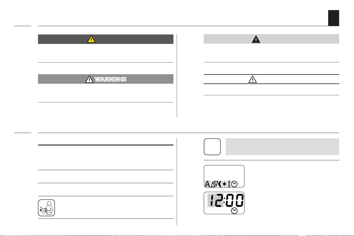
i
Flashing menu icon and setting
parameters have a grey
background.
Information about opening the
menu and setting the parameters
can be found on page 30.
5
Page 6

2.3 Technical Term - Denition
i
EN
DIN EN 13659
"Shutters and external Venetian blinds -
Performance requirements including safety."
◆ This standard determines the performance require-
ments that externally attached shutters and blinds
must full. It also contains signicant hazards with
regard to the design, transportation, installation,
operation and maintenance of these shutters and
blinds.
Blinds
◆ Roller shutters
Obstacle detection
◆ If the roller shutters hit an obstacle in the DOWN ( t )
direction, the superrollo GW240 / GW245 is switched
o, see page 13.
Overload cut-o
◆ If the drive jams in the UP ( ▲ ) direction (for exam-
ple, due to ice), the superrollo GW240 / GW245 is
switched o, see page 13.
End points
◆ An end point is dened and set for each running
direction of the roller shutter. Once this point has
been reached, the superrollo GW240 / GW245 switches o and the roller shutter stops.
Running Time Limit - Transient Operation (KB)
◆ The roller shutter belt winder superrollo GW240 /
GW245 is not designed for continuous operation.
Transient operation dened the maximum permissible running time, see page 15/ 18.
6
Page 7
3. Included in delivery
i
a)
b)
c)
d)
e)
EN
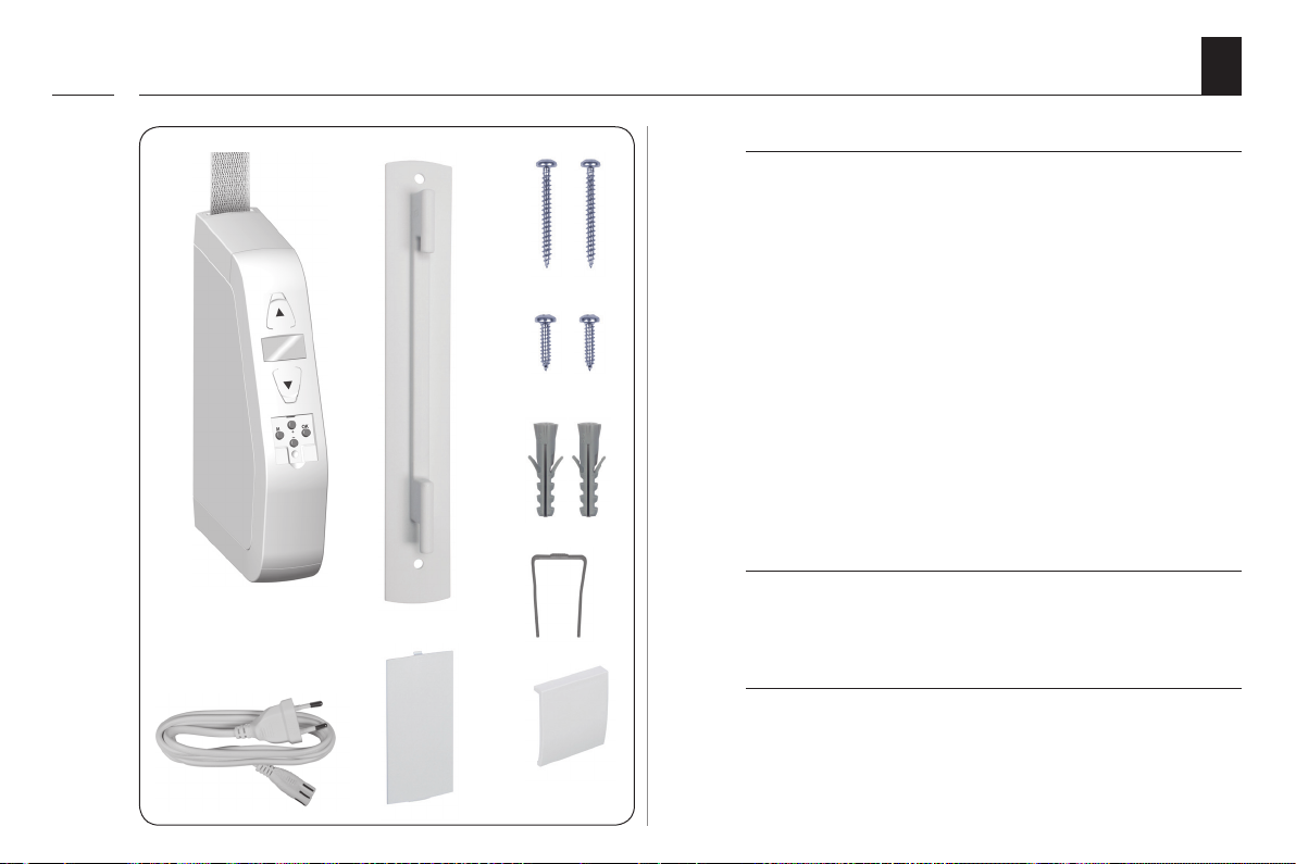
Included in delivery
a) 1 x superrollo GW240 or
1 x superrollo GW245
b) 1 x Wall bracket
c) 2 x Assembly screws (4 x 40 mm)
d) 2 x Assembly screws (4.2 x 19 mm)
e) 2 x Wall plugs (S6 x 30 mm)
f) 1 x Disengaging bracket
g) 1 x Connecting cable with Euro plug
h) 1 x Reel compartment cover
i) 1 x Cover plate
j) 1 x Instruction manual (not illustrated)
g)
h) i)
f)
After unpacking please check and compare...
the contents of the package with the above specied.
Check the details on the type plate
Check that the voltage / frequency on the type plate
corresponds to the local mains conditions.
7
Page 8
4. Overview of the superrollo GW240 / GW245
i
EN
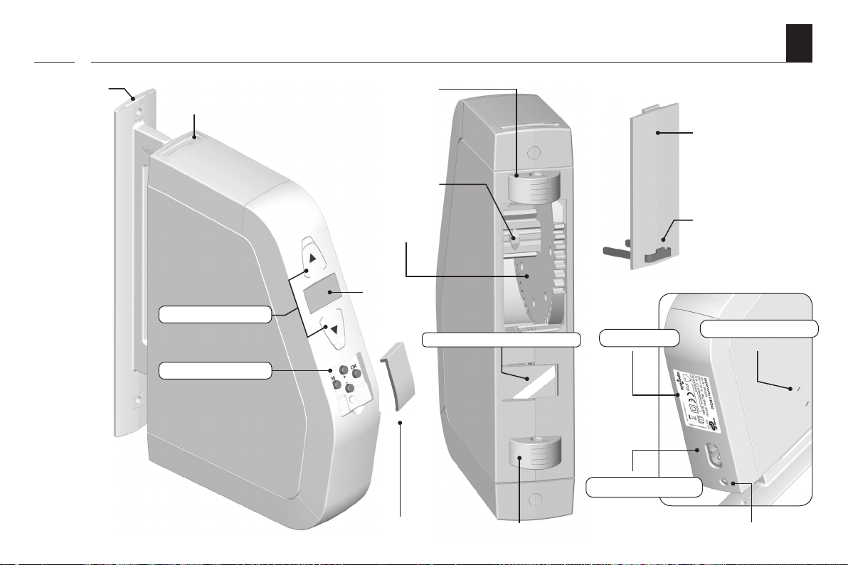
Wall bracket
Belt inlet
Operating buttons
Setting buttons
Mounting
Fastening
hook
Reel
Display
Assembly locking device
Type plate
Mains connection
Reel compartment
cover
Disengaging bracket
Drive release
Cover plate
Mounting
Connection socket for the light sensor
8
Page 9
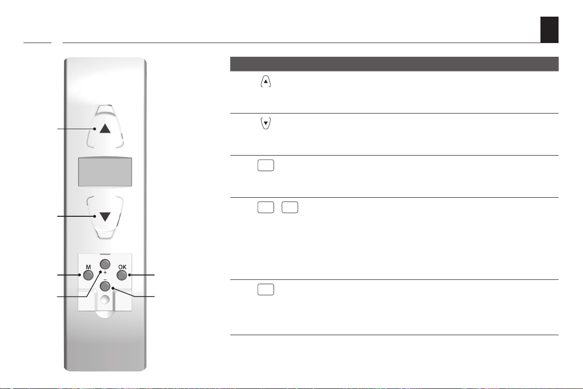
4.1 Operating buttons
M
+
-
OK
i
1)
2)
3)
4)
6)
5)
Pos. Symbol Description
1) Up / Stop button
◆ The roller shutter travels upwards
◆ The roller shutter stops
2) Down / Stop button
◆ The roller shutter travels downwards
◆ The roller shutter stops
3)
4)
5)
6)
/
Menu button
◆ Call up the main menu
◆ Back to previous menu or standard display
Plus button / minus button
◆ Selecting a menu in the main menu
◆ Setting of parameters (more / less)
● short press = gradual setting
● long press = fast setting
◆ Switch functions on / o
OK button
◆ Conrms and opens the selected menu
◆ Conrm and save entry
◆ Continue to next entry
EN
9
Page 10
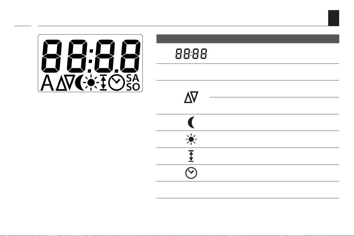
4.2 The display and its symbols
A
SA
SO
i
EN
Pos. Symbol Description
1) Time / setting parameters
10
2)
3)
4) Automatic dusk function
5) Automatic solar function
6) Setting the end points
7) Setting the time / date
8)
Switching automatic mode on/o
Direction of travel - up / down
Switching times (opening / closing time)
Setting the weekend switching times
Page 11
4.3 The standard display and the main menu
i
EN
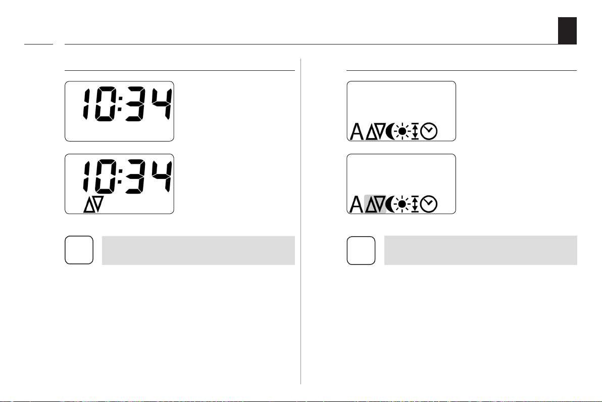
The standard display (see example)
Displays the time, no
automatic functions
are active.
Displays the time and
the activated automatic
timer.
Manual operation is only possible from the
i
standard display.
The main menu
Enables display and
selection of the individual
functions and menus.
The selected menu
ashes, e.g. the switching
times.
Manual operation is not possible from the
i
main menu.
◆ No automatic switching commands will
be executed during the conguration
process.
◆ If no button is pressed within 60 seconds,
the display automatically changes back
to the standard display.
11
Page 12

5. Functional description
i
EN
The superrollo GW240 / GW245 is an electric roller shutter
belt winder designed for use inside. The unit is installed
as a surface-mounted device.
The power supply is provided via the enclosed connecting cable with a mains plug and a small appliances plug.
Features and
control options:
◆ Operational demonstrator
◆ Manual operation
◆ Switching automatic mode on/o
◆ Four switching times, with a separate switching
time for
UP ( ▲ ) and DOWN ( t ) for:
● Monday to Friday
● Saturday and Sunday
◆ Automatic solar function (with light sensor)
◆ Automatic dusk function (with light sensor)
◆ Automatic summer/winter time - changeover
◆ End point setting
◆ Permanent storage of the settings
◆ Obstacle detection
◆ Overload cut-o
◆ Resetting to the default factory settings (Reset)
12
Page 13
5.1 Description of the safety functions
i
EN
Obstacle detection
The movement of the belt is monitored. If the roller shutters
hit an obstacle in the DOWN ( t ) direction, the belt
will stop moving and the superrollo GW240 / GW245 is
switched o.
Once the system has switched o, it is not
possible to directly operate the drive in the
i
same direction.
◆ First, run the belt winder back in the op-
posite direction and remove any possible
obstacle.
◆ Then it is possible to operate the drive in
the original direction again.
There is a risk of injury if the obstacle detection is
not working.
◆ The belt must be wound on as evenly as possible to
ensure safe and correct functioning of the obstacle
detection function.
◆ Please ensure that the belt winds as straight and
evenly as possible into the device during its subsequent cycle after the obstacle detection system has
triggered.
Overload cut-o
The superrollo GW240 / GW245 is equipped with an
overload cut-o system.
If the drive jams in the UP ( ▲ ) direction (for example,
due to ice), the superrollo GW240 / GW245 is switched o.
◆ First remove the cause of the overload.
◆ Then the superrollo GW240 / GW245 is fully
operational again in both directions.
13
Page 14

5.2 Conduct in the event of power failure
i
EN
After a power failure the time ashes in the display
and the installation wizard is active.
Time and date after a power failure
The date and time stop with a power failure and need
to be reset with the installation wizard, see page 32.
Data retention following a power failure
All settings are permanently saved. The configured
switching times are retained even following extended
power failure.
14
Page 15

6. Technical Specications
i
EN
Power supply
Supply voltage: 230 V ~ / 50 Hz
Nominal power: 70 W
Consumption: Standby: < 0.5 W
Mechanical capacity
Nominal torque: 8 Nm
Maximum speed: 36 rpm
Maximum tractive force:
End tractive force: 13 kg
30 kg, see page 54 /
Tractive force diagram
Operating conditions
Transient operation (KB):
Protection class: II
Protection type:
Setting ranges:
- Automatic solar function 2,000 to 20,000 Lux
- Automatic dusk control 2 to 5 Lux
4 minutes
(maximum running time)
IP20 (only for use in dry rooms)
Operating conditions
Number of switching
times:
Mains connecting cable: 2 x 0.75 mm2 (H03VVH2-F)
Permissible ambient temperature:
Sound pressure level (LpA): ≤ 70 dB(A)
4 (up and down)
0 °C to +40°C
15
Page 16
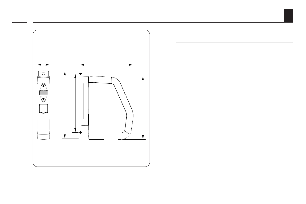
6.1 Dimensions
i
EN
superrollo GW240 / GW245
Item no.: SR10240 / SR10245
16
37
199
172
All dimensions in mm
155
OBEN
185
Page 17

6.2 Permissible roller shutter belts
i
EN
ATTENTION!
The superrollo GW240 / GW245 may be damaged if
excessively long belts are used.
Only use belts of the permissible lengths.
Table 1: Permissible roller shutter belts
superrollo:
Item No.:
Belt width:
15 mm (Mini-belt) 1.0 mm 5 m
23 mm (Standard belt)
Table 2: Permissible shutter surface area (m2)
Roller shutter type: Weight/m
Plastic roller shutters (4.5 kg/m2) Approx. 5 m
Aluminium and wooden roller shutters (10.0 kg/m2) Approx. 2.5 m
Belt thick-
ness
1.0 mm 5 m
1.3 mm 4 m
1.5 mm 3.4 m
2
GW245 (Mini Belt)
i
SR10245
Permissible shutter surface area (m2)
The specications are intended for guidance
only and apply to an ideal installation
situation.
The actual values may vary due to local
conditions.
GW240
SR10240
Maximum belt length
2
2
Approx. 5 m
Approx. 2.5 m
2
2
17
Page 18
7. Safety instructions
i
EN
The use of defective equipment can lead to personal
injury and damage to property (electric shocks, short
circuiting).
◆ Never use defective or damaged equipment.
◆ Check the superrollo GW240 / GW245 and the
provided mains cable beforehand for damage.
◆ Should you discover damage to the equipment,
please consult our customer service department
(see page 60).
Incorrect use leads to an increased risk of injury.
◆ Train all personnel to use the superrollo
GW240 / GW245 safely.
◆ This device may be used by children from 8 years
of age upwards as well as by persons with reduced
physical, sensory or mental capacities or with lack
of experience and knowledge if they are supervised
or have been instructed on how to use the device
safely and if they understand what dangers may
resulted from this.
◆ Children must not play with the device. Cleaning and
user maintenance may not be carried out by children
without supervision.
◆ Watch the moving roller shutters whilst carrying out
the settings and during normal operation, and keep
other people away from the area to avoid injury in
the event the shutters suddenly slip.
◆ Carry out all cleaning work on the roller shutters
whilst the device is disconnected from the mains
power.
The mains socket and plug must be easily accessible
at all times.
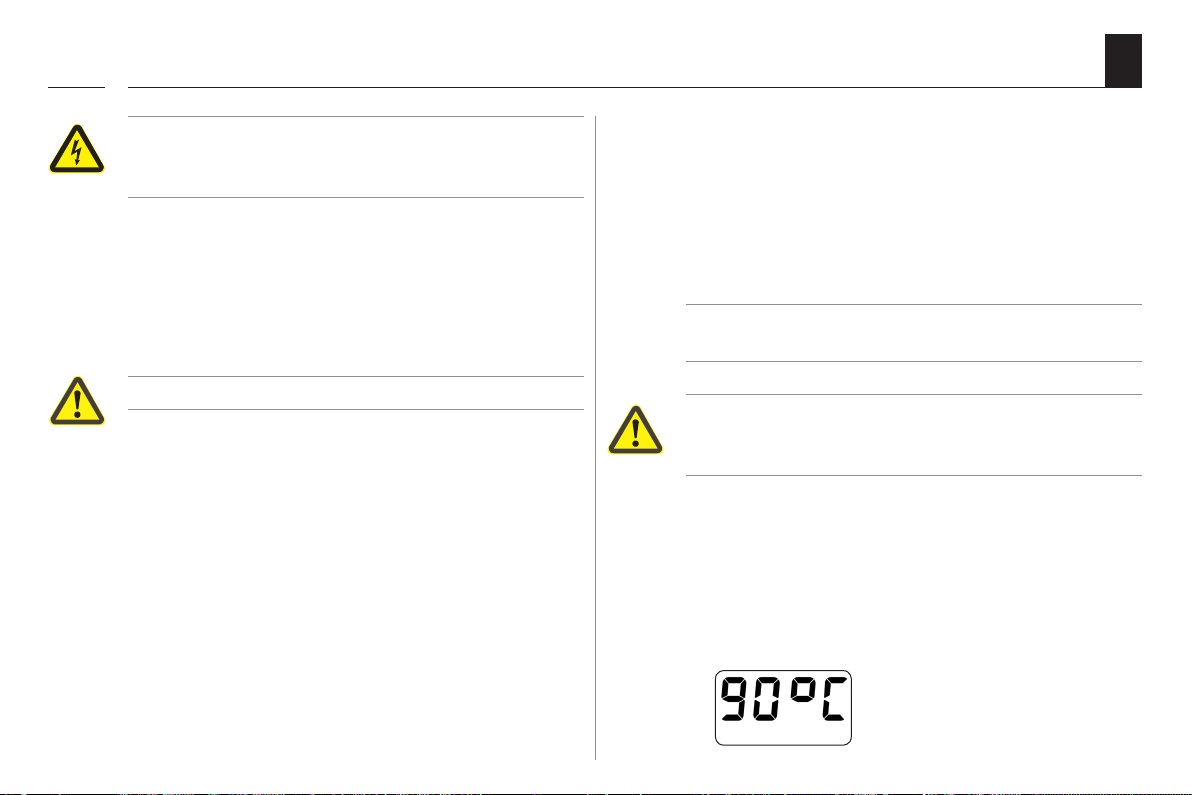
Exceeding the maximum permissible running time
(KB) may overload and damage the superrollo GW240 /
GW245.
◆ The maximum permissible running time for a cycle
may not be exceeded when the equipment is in operation. For this reason, the superrollo GW240 / GW245
has an automatic running time limit (KB) of four
minutes.
◆ If the running time limit is triggered then the
following error message will appear:
18
Page 19

7. Safety instructions
i
EN
◆ If the running time limit is triggered, then the
superrollo GW240 / GW245 must be left for at
least 12 minutes to cool down.
During the cooling period the superrollo
GW240 / GW245 may not be used and the
i
temperature is displayed for as long as is
necessary.
◆ Full operational availability is re-established
after approx. one hour.
7.1 Intended use
i
Only use the superrollo GW240 / GW245 for opening and
closing roller shutters with a permissible belt.
Mechanical locks of any kind are not suitable
i
for automated operation with this device.
According to DIN EN 13659, it is necessary to determine
that the movement conditions for the shutters are maintained in accordance with EN 12045.
◆ The displacement must be of at least 40 mm on the
lower edge in the rolled-out position with a force of
150 N in the upwards direction.
◆ In doing so, it must be ensured that the extending
speed of the shutters for the nal 0.4 m is less than
0.15 m/s.
Only use the manufacturer's original spare parts.
◆ By doing so, you avoid risk of malfunctions and
damage to your superrollo GW240 / GW245.
◆ As the manufacturer, we provide no guarantee for
the use of third-party components and accept no liability for consequential damage resulting from such.
◆ All repairs to the superrollo GW240 / GW245 must
be undertaken by authorised customer service
personnel.
19
Page 20

7.1 Intended use
i
Operating conditions
◆ Only operate the superrollo GW240 / GW245
in dry rooms.
◆ An easily accessible 230 V/50 Hz mains socket
must be available at the installation site.
◆ The roller shutters must run up and down
smoothly and should not stick.
◆ The mounting surface for the superrollo
GW240 / GW245 must be at.
7.2 Improper use
i
EN
20
Using the superrollo GW240 / GW245 for purposes
other than previously mentioned is impermissible.
There is a risk to life caused through short circuiting
and electric shocks if the superrollo GW240 / GW245
is used outside.
◆ Never install or operate the superrollo
GW240 / GW245 outside.
Page 21
8. Safety instructions for the installation
1
2
3
4
5
6 mm
i
EN
Poor routing of the belt can cause the belt to fail
and leads to unnecessary loads on the superrollo
GW240 / GW245.
◆ Install the belt winder so that the belt runs as
straight as possible into the device, in order to
avoid unnecessary friction and wear.
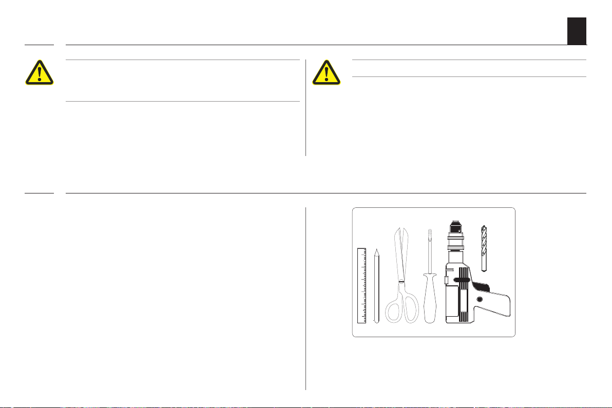
8.1 You will require the following tools
i
◆ Screwdriver (cross recessed head)
◆ Scissors
◆ Carpenter's gauge or measuring tape
◆ Pen
◆ A drilling machine and a 6 mm masonry drill,
if new mounting holes need to be drilled.
Incorrect installation can lead to property damage.
◆ Strong forces are exerted during operation of the
system which require secure installation on a rm
base.
21
Page 22

9. Preparation for installation
i
1. Take measurements. Check that there is sucient
space for the superrollo GW240 / GW245.
2. Remove the old belt winder, if you are carrying out
a conversion to an existing roller shutter system.
2.1 Let the roller shutter move fully down, until the slats
are completely closed.
2.2 Remove the old belt winder and unreel the belt.
CAUTION!
There is a risk of injury from the pre-tensioned
springs on the old belt winder.
◆ The spring unit of the old belt winder may suddenly
recoil when it is removed.
◆ Hold the spring unit rmly when loosening the belt
and allow it to recoil slowly until the spring unit has
completely unwound.
EN
22
Page 23

9. Preparation for installation
i
3. Prepare the belt.
3.1 Cut the belt o approx. 20 cm under the mounting
position.
3.2 Fold the end of the belt over by approx. 2 cm and cut a
short slit in the centre. This enables you to subsequently
hook the belt onto the reel.
Recommendation
The belt must run as straight and freely as possible.
For sti roller shutters, mount a deection roller on
the belt box. This helps to prevent unnecessary friction
and wear to the belt.
EN
20 cm
Accessories, see page 57.
23
Page 24

10. Mounting the wall bracket
i
EN
Note for mounting on window frames, etc.
Weak window frames may break.
◆ When mounting on window frames, please check
their structure and load capacity. Especially when
mounting onto designs made of synthetic materials,
the fastening screws must be screwed tight and must
not loosen during operation.
◆ If required, ask your window manufacturer before
fastening the belt winder onto a window frame made
of synthetic materials.
1. Use the provided mounting holes.
Two mounting holes are required to fasten the belt
winder. Generally, it is possible to use the existing
mounting holes of the old belt winder to screw the
wall brackets in place.
2. Draw on the new mounting holes.
Hold the wall bracket onto
the desired installation
position and draw on both
mounting holes if new
mounting holes need to be
drilled.
3. Drill mounting holes (only required for wall mounting).
Drill the mounting holes with a 6 mm masonry drilling
machine and place the provided wall plugs into the
drilled holes.
24
Page 25

10. Mounting the wall bracket
i
The letterings "TOP" and "OBEN" on the wall
bracket indicates the correct mounting posi-
i
tion.
4. Screw on the wall bracket with the screws provided
and ensure that the right side is facing upwards (TOP/
OBEN).
Use the correct type of screw depending on
the mounting surface, see the 'included in
i
delivery' section on page 7.
◆ Wall mounting = 4 x 40 mm
◆ Mounting onto window
frame = 4.2 x 19 mm
EN
Indication of the correct mounting
position on the wall bracket.
Correct mounting of the wall
bracket.
25
Page 26
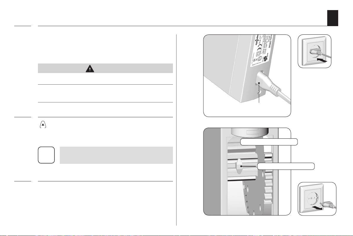
11. Drawing in and fastening the belt
i
1. First, plug in the small appliances plug into the mains
connection of the superrollo GW240 / GW245 and
subsequently the mains plug into the socket.
CAUTION!
There is a risk of injury from the reel.
Never reach into the reel compartment when
the motor is running.
2. Press the Up button until the Fastening hook
are easily accessible in the reel compartment.
As no end points have been set yet, the drive
i
will stop as soon as you release the button.
3. Remove the mains plug again from the socket.
EN
The small appliances plug in
the mains connection
Reel compartment
Fastening hook
26
Page 27
11. Drawing in and fastening the belt
i
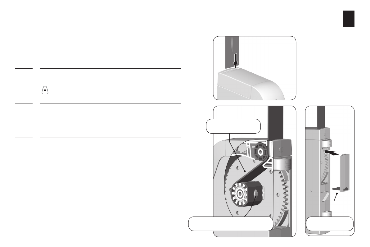
4. Next, draw-in the belt into the superrollo GW240 / GW245
from the top.
Feed the belt into the device, as shown in the image,
and slide it over the Fastening hook from below.
5. Re-insert the mains plug into the socket.
6. Press the up button until the belt has fully
wound once around the reel.
7. Pull the belt tight when winding, so that the deection
roller turns at the same time.
8. Remove the mains plug again from the socket.
9. Finally, place the provided reel compartment cover onto
the reel compartment.
EN
Belt path in
the device
Pull the belt over the Fastening
hook from below
Reel compartment
cover
27
Page 28

12. Mounting the superrollo GW240 / GW245
i
1. Slide the superrollo GW240 / GW245 onto the wall
bracket from below until it engages.
Otherwise, the superrollo GW240 / GW245 may fall o
again.
WARNING!
A damaged connecting cable may cause a short
circuit.
Ensure that the connecting cable is not pinched or
damaged during the mounting process.
EN
28
Page 29
12. Mounting the superrollo GW240 / GW245
i
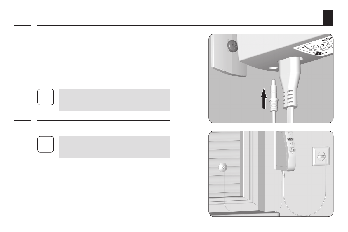
2. Mount the light sensor (not included, see page 57,
Accessories).
◆ Insert the light sensor plug into the designated
connection socket on the bottom of the
superrollo GW240 / GW245.
◆ Subsequently secure the light sensor to the
window pane using the suction cup.
The position of the light sensor on the window
pane determines the point at which the roller
i
shutters will close to in the event of sunlight.
3. Re-insert the mains plug into the 230 V / 50 Hz socket.
Leave the bottom cover plate of the setting
buttons open until all settings have been
i
carried out.
EN
29
Page 30

13. Introduction to opening and setting the functions
+
-
M
+
OK
+
OK
M
i
EN
1.
2.
3.
Open the
Pressing the menu button in the standard
display causes the main menu to open.
/ -
Open the menu by pressing the OK
button, see example.
Select the desired menu.
The selected menu is indicated by a
ashing icon.
main menu.
4.
5.
6.
/ -
By conrming the setting you will return
to the main menu.
Back to the normal display
Briey pressing the menu button causes
i
Select the desired setting (e.g. On).
the display to go back one menu step.
OFF ashes.
30
Page 31
14. Initial commissioning with the help of the installation wizard
i
EN
The wizard automatically guides you through the conguration process for initial commissioning or after a
software reset (see page 47).
With the help of the installation wizard you will be
guided through the rst basic settings.
Following power failure, the installation
i
wizard will be started with the resetting of
the date and time.
Restart the installation wizard
As long as the installation wizard is still running,
it can be restarted by pressing the menu button.
Readiness for operation
The superrollo GW240 / GW245 is ready for use
as soon as the installation wizard has nished.
In the main menu you can change your settings
at any time, or add additional settings.
Additional information about conguring
the end points
The end points must be congured for the roller shutters
to stop at the desired upper and lower positions.
It is imperative that both end points are congured,
otherwise malfunctions may occur.
If the superrollo GW240 / GW245 is operated
without an end point setting, the drive will
i
continue to run as long as one of the two
control buttons is actuated.
The automatic functions remain blocked
until the end point setting is congured.
31
Page 32

14. Initial commissioning with the help of the installation wizard
OK
OK
OK
OK
OK
+
+
+
OK
i
EN
1. The installation wizard appears as soon
as the plug is plugged into the socket.
All icons and digits in the display will ash.
2.
3.
Activate the time setting function.
/ - Set t
(hours:minutes) and conrm each entry.
he current time
4.
5.
6. Next, the upper end point must be set,
/ - Set t
(day.month) and conrm each entry.
/ - Set the current year and conrm
the entry.
see the next page.
he current date
32
Page 33

14. Initial commissioning with the help of the installation wizard
OK
i
EN
6. Set the upper end point.
6.1 Press and hold the Up button.
The roller shutter travels up.
6.2 Tighten the belt slightly, until it is
tensioned by the weight of the
roller shutters.
6.3 Release the Up button, as soon as the
roller shutter reaches the desired
position for the upper end point.
The roller shutter stops.
6.4
6.5
/
If necessary, the upper end point can
be corrected once more.
Save the upper end point.
ATTENTION!
Setting the wrong upper end point may lead to
overload or damage the superrollo GW240 / GW245
or the drive.
◆ Do not set the upper end point right up to the
limit stop.
◆ Release the Up button promptly and never allow
it to extend beyond the respective end point.
7. Next the lower end point must be set,
see the next page.
Please ensure that the belt is not excessively
i
slack when reaching the lower end point.
33
Page 34

14. Initial commissioning with the help of the installation wizard
OK
i
EN
7. Set the lower end point.
7.1 Press and hold the Down button.
The roller shutter travels down.
7.2 Release the Down button, as soon as the
roller shutter reaches the desired position
for the lower end point.
The roller shutter stops.
7.3
7.4
/
If necessary, the lower end point can be
corrected once more.
Save the lower end point.
After a period of time it may be necessary to
recongure the end points as the belt may
i
elongate during the process of operation,
see page 45.
8. The standard display is shown as soon
as the nal setting is conrmed.
The superrollo GW240 / GW245 is
now ready for operation.
34
Page 35

15. Manual operation
Manual operation is possible in any of the modes and
has priority over the programmed automatic functions.
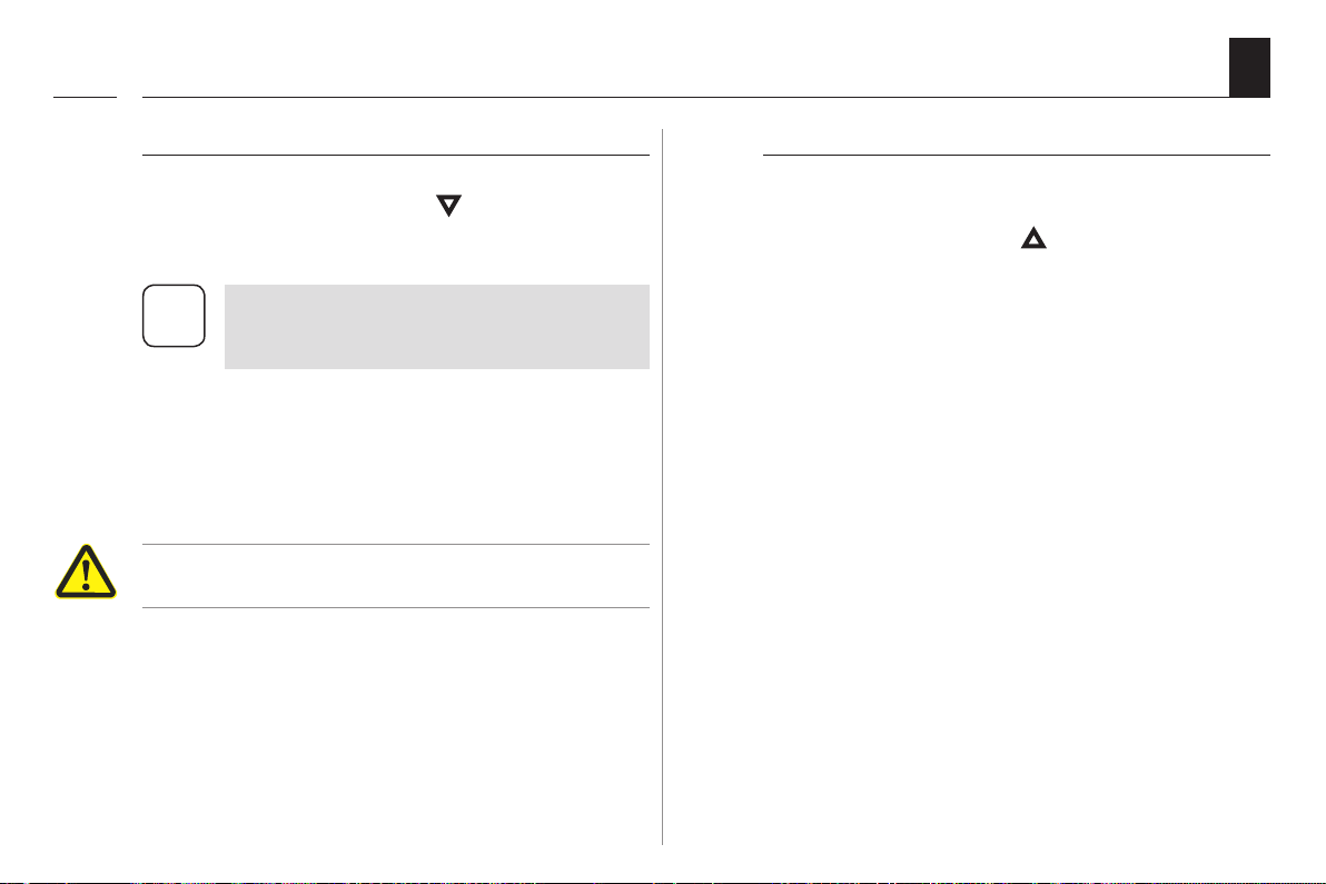
1. Open the roller shutters.
By briefly pressing the button, the
roller shutters will move to the upper
end point.
EN
2.
or
Stop the shutters in the interim.
3. Close the roller shutters.
By briefly pressing the button, the
roller shutters will move to the lower
end point.
Operating buttons
35
Page 36

16. Description of the functions and setting options in the main menu
M
A
Functions in the main menu
Pos. Symbol Description
EN
36
In the main menu, you can call up
and set all of the functions for the
superrollo GW240 / GW245.
Manual operation is not possi-
i
ble from the main menu.
◆ No automatic switching com-
mands will be executed during the conguration process.
◆ If nothing is entered within 60
seconds, the display changes
back to the standard display.
1)
2) Switching times (opening / closing time)
3) Automatic dusk function (with light sensor)
4) Automatic solar function (with light sensor)
5) End point setting
6) Time and date
Automatic operation
Page 37

16.1 Switching automatic mode on/o
OK
OK
A
M
+
+
EN
Automatic mode [ On ]
◆ All previously entered automatic mode functions
are active.
◆ Manual operation is also possible in automatic
mode.
Automatic mode [ OFF ]
◆ All previously entered automatic mode functions
are deactivated.
◆ All automatic icons are switched o in the
standard display.
1.
2.
3.
4. The main menu appears again once
Open the main menu.
/ - Select automatic mode and open
the menu.
/ - Select the desired functions and
conrm the entry.
On = Automatic mode on
OFF = Automatic mode o
this is conrmed with the OK button.
37
Page 38

16.2 Setting the switching times (opening and closing times)
OK
M
+
EN
You can congure four dierent opening and closing
times for the superrollo GW240 / GW245 in order to open
or close your roller shutters at your preferred times.
You can set the following switching times:
From Monday to Friday:
1 x opening time [ ▲ ] + 1 x closing time [ t ]
For Saturday and Sunday:
1 x opening time [ ▲ ] + 1 x closing time [ t ]
The dierent switching times automatically
i
appear one after the other.
◆ By setting the switching times, the
automatic mode is automatically
switched on.
Deactivating the switching times [ OFF ]
Each switching time can be deactivated individually.
When setting the hours between 23:00 and 0:00, the
value OFF appears in the display.
Example:
OFF = Switching time o
1.
2.
Open the main menu.
/ - Select the switching times and
open the menu.
38
Page 39

16.2 Setting the switching times (opening and closing times)
OKOKOKOKOK
OK
+
+
+
EN
3. Set the opening time [ ▲ ] for Monday to Friday:
3.1
4. Set the closing time [ t ] for Monday to Friday:
4.1
/ - Set the desired opening time
(hours: minutes) and conrm each entry.
/ - Set the desired closing time
(hours: minutes) and conrm each entry.
5. Set the opening [ ▲ ] and closing time [ t ] for
Saturday and Sunday:
5.1
6. After the last setting. the main menu
/ - Select the desired switching times
as shown in points 3.1 and 4.1.
appears once again.
39
Page 40

16.3 Setting the automatic dusk function
OK
OK
M
+
+
EN
The automatic dusk function causes the roller shutters
to close to the lower end point automatically.
Automatic dusk function with connected light
sensor
At twilight, the roller shutters
will lower to the lower end
point after approx. 10 seconds. The roller shutters will
open again once the congured opening time is reached
or in the event of a manual Up
command.
The required twilight limit is
congurable.
The automatic dusk function is only
i
executed once per day.
◆ By setting the automatic dusk function,
the automatic mode is automatically
switched on.
◆ Mounting the light sensor see page 42,
Automatic solar function.
1.
2.
3.
Open the main menu.
/ - Select the automatic dusk function and
open the menu.
/ - Switch the automatic dusk function on
and conrm the entry.
On = Automatic dusk function on
OFF = Automatic dusk function o
40
Page 41

16.3 Setting the automatic dusk function
+
OK
4. Setting the twilight limit:
EN
4.1
4.2
/ - Set the desired limit.
ACTUAL value
Currently measured brightness (e.g. 10).
"- -" = too bright
SET value
Congurable set limit
01 = very dark, approx. 2 Lux
15 = less dark, approx. 50 Lux
If the set limit value is not met due to the onset of twilight, the roller shutters will close.
Return to main menu.
41
Page 42

16.4 Setting the automatic solar function
The automatic solar function enables brightness-dependent control of the roller shutters in combination
with the light sensor. To do this, the light sensor is secured
to the window pane with a suction cup and then plugged
into the superrollo GW240 / GW245.
Automatic solar function
Automatic moving up and down of the roller shutter
once a set limit is exceeded. The roller shutter end position can be freely selected by changing the light sensor
position.
EN
Example installation
42
Please note the state of the sun icon on the
i
standard display.
◆ During the activated automatic solar
function, the corresponding icon ashes
in the standard display as soon as sunlight
is detected.
◆ By setting the automatic solar function,
the automatic mode is automatically
switched on.
The automatic solar function will be terminated
and must be reactivated if required after the
following events:
◆ After manual actuation.
◆ After execution of an automatic function.
◆ After the upper end point is reached.
Page 43

16.4 Setting the automatic solar function
Automatic lowering
EN
If the sensor detects uninterrupted sunlight for 10
minutes, the shutter will descend until its shadow
covers the light sensor.
Automatic clearing
After approx. 20 minutes, the roller shutter is
automatically raised a small amount to uncover the
sensor. If the sun continues to shine, then the roller
shutter remains in this position. If the brightness
decreases below the set limit, it returns to the
upper end point.
The above-mentioned delay times can be
exceeded in the event of changing weather
i
conditions.
10 mins
sun
After 20
mins
43
Page 44
16.4 Setting the automatic solar function
OK
OK
M
+
+
+
OK
EN
1.
2.
3.
Open the main menu.
/ - Select the automatic solar function and
open the menu.
/ - Switch the automatic solar function on
and conrm the entry.
On = Automatic solar function on
OFF = Automatic solar function o
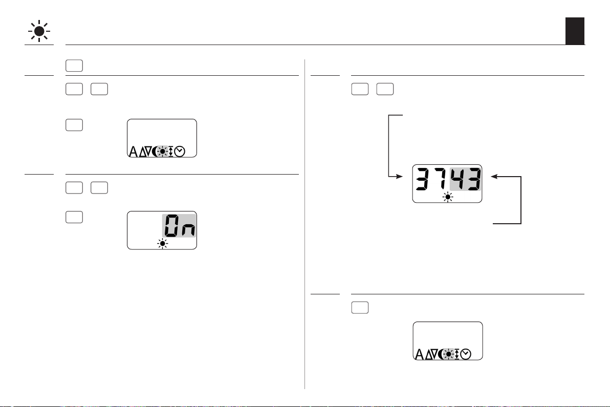
4. Setting the solar limit value:
4.1
4.2
/ - Set the desired limit.
ACTUAL value
Currently measured brightness (e.g. 37).
"- -"= too dark
SET value
Congurable set limit
31 = minimal sun, approx. 2000 Lux
45 = bright sunlight, approx. 20000 Lux
Return to main menu.
44
Page 45

16.5 Setting the end points
OK
M
+
EN
1. or
centre position.
2.
3.
the menu.
First move the roller shutters to the
Open the main menu.
/ - Select the end point and open
Setting order
Set the upper end point,
see page 33.
Set the lower end point,
see page 34.
45
Page 46

16.6 Set time and date
OK
M
+
EN
1.
2.
Open the main menu.
/ - Select the time and date and open
the menu.
Set the year,
see page 32.
Setting order
Set the time (hours: minutes),
see page 32.
Set the date (day. month),
see page 32.
46
Page 47

17. Erase all settings, software reset
M
-
i
EN
If necessary, you can erase all of your settings and return
the superrollo GW240 / GW245 system to its original
factory settings.
1. Remove the cover plate from the setting buttons.
2.
+ OK + + +
Simultaneously press and hold the four buttons
for 4 seconds.
3. This displays the software version for the
superrollo GW240 / GW245.
Example
4. After four seconds all icons on the display will light up.
5. Release the buttons and all of the settings will be deleted;
the installation wizard will appear automatically.
6. Carry out the initial settings in the installation wizard,
see page 31.
47
Page 48

18. Removing the superrollo GW240 / GW245 (e.g. in the event of a move)
M
i
1. Remove the cover plate from the setting buttons.
EN
2.
3. Fully close the roller shutters.
4. Continue to press and hold the down button.
5. In doing so, pull out the belt as far as possible from the
6. Remove the mains plug from
7. Press the assembly locking device on the back part
+ OK + + + -
Erase all settings. Simultaneously press and hold the
buttons for 4 seconds.
top of the superrollo GW240 / GW245.
the socket and the small
appliances plug from the
superrollo GW240 / GW245.
and remove the superrollo GW240 / GW245 from the
wall bracket by pulling it downwards.
Assembly locking device
48
Page 49

18. Removing the superrollo GW240 / GW245 (e.g. in the event of a move)
i
8. Remove the reel compartment cover and check
the position of the fastening hook.
9. If necessary, move the fastening hook into an
easily accessible position.
9.1 For this, plug the mains cable into the superrollo
GW240 / GW245 and into the socket.
CAUTION!
There is a risk of injury from the reel.
◆ Never reach into the reel compartment when
the motor is running.
◆ Always remove the mains plug before touching
the reel compartment.
10. Finally, remove the mains plug again from the socket.
11. Release the belt from the fastening hook and pull
it out completely from the top of the superrollo
GW240 / GW245.
EN
12. Finally, unscrew the wall bracket.
49
Page 50

19. Removing the belt in the event of unit failure
i
EN
In the event that the superrollo GW240 / GW245 unit
fails and the motor no longer runs, you can use the
disengaging bracket provided in order to fully remove
the belt from the belt winder unit, without the need for
cutting it.
WARNING!
There is a risk of injury as the roller shutters may
slam shut or fall in an uncontrolled manner.
◆ Secure the roller shutters from falling, for example,
by laying something underneath it.
◆ Hold on to the belt tightly to stop the roller shutters
from slamming shut or falling in an uncontrolled
manner.
◆ Get a second person to help you unlatch the unit.
1. Remove the mains plug from
the socket.
2. Turn the superrollo GW240 / GW245
completely to the side.
3. Release the drive with the help of the supplied disen-
gaging bracket. A small amount of resistance must be
overcome when pressing.
50
4. Maintain pressure on the disengaging bracket and pull
the belt out of the superrollo GW240 / GW245 as far as
possible.
Drive release
Storage bay
5. Remove the reel compartment cover. Release the belt
from the fastening hook and fully pull it out of the
superrollo GW240 / GW245.
6. Press the assembly locking device on the back part
and remove the superrollo GW240 / GW245 from the
wall bracket by pulling it downwards.
7. Place the disengaging bracket back into the storage
compartment.
Page 51

20. What to do if... ?
i
Fault Possible cause / solution
EN
... the superrollo GW240 / GW245 indicates
no functions?
... the superrollo GW240 / GW245 fails to react at
the congured switching time?
... the roller shutters no longer stop at the
congured end points?
... the roller shutters stop as soon as the operating
button is released?
... the superrollo GW240 / GW245 rotates in
the wrong direction?
... the roller shutters stop suddenly during
upward travel?
Check the power supply incl. connecting cable and plug.
a)
There may have been a power failure, see page 14. Reset the
time and date with the help of the installation wizard, see page 32.
b) The automatic mode may have been deactivated. Switch the
automatic mode on, see page 37.
The end points may be displaced due to elongation of the belt.
Re-adjust the end points, see page 45.
During initial installation or after a reset, the will be no end points
set. In this case, you will need to reset the end points with the help
of the installation wizard, see page 31.
Possibly the belt is wrapped around the reel incorrectly,
see page 27.
a) The drive may be jammed, for example, due to the
roller shutters freezing up or other obstacles.
b) The roller shutters may not be running suciently smoothly.
Check the roller shutters and roller shutter guides.
d) The roller shutters may be too heavy. The maximum tractive force
of the belt winder has been exceeded, see page 54.
51
Page 52

20. What to do if... ?
i
Fault Possible cause / solution
... the roller shutters stop during downward travel? a) The roller shutters may have hit an obstacle.
... the temperature display appears and the
superrollo GW240 / GW245 fails to operate in
either direction?
... the superrollo GW240 / GW245 fails to react
properly either manually or automatically?
EN
Move the roller shutters back up and remove the obstacle.
b) Slats have shifted out of alignment.
If possible, move the roller shutters back up and realign the slats.
c) The roller shutters scrape against the window frame or inside
the roller shutter box due to the lack of a pinch roller or insulation
material may have come free and is jamming the roller shutters.
Open the roller shutter box and rectify the fault. Lubricate any
sti areas with gliding wax.
d) The roller shutters are too light.
Increase the weight of the roller shutters by, for example, adding
a piece of at steel to the bottom slat.
The maximum running time of the drive has been exceeded,
see page 15/18.
The motor is too hot. The belt winder will be fully operational
again in approx. 1 hour.
The superrollo GW240 / GW245 is no longer ready for operation.
Carry out a software reset in accordance with the instructions on
page 47 and test the superrollo GW240 / GW245 using the default
factory settings.
52
Page 53

21. Information about maintenance and care of your equipment
i
EN
Maintenance
CAUTION!
A lack of maintenance can lead to personal injury
through damage to your superrollo GW240 / GW245
and the roller shutter system.
◆ Please check the superrollo GW240 / GW245 and all
of your roller shutter components regularly
for damage.
● Regularly check the superrollo GW240 / GW245
for correct functioning.
● The blinds must not be damaged.
● The belt may not be frayed.
● The deection roller on the roller shutter box
must move freely.
● The reel plate in the roller shutter box must be
fastened and stable. It may become less stable
when used over a longer period of time.
◆ Damaged components should be exchanged by
a specialist roller shutter rm.
Maintenance
You can clean the superrollo GW240 / GW245 using
a damp cloth. Please do not use aggressive or abrasive
cleaning agents.
53
Page 54

22. Tractive force diagram
i
EN
2
3
54
1
Lifting weight kg ]
Belt length m ]
5
Lifting weight [Kg]
1
Belt thickness 1.0 mm
2
Belt thickness 1.3 mm
3
Belt thickness 1.5 mm
4
Belt length [m]
5
4
Page 55

23. Factory Settings
i
Pos. Description Status / settings
1) Automatic operation On
2) Switching times (opening / closing time) On
3) Opening times (Monday to Friday) 7 am
4) Closing times (Monday to Friday) 8 pm
5) Opening times (Saturday and Sunday) 8 am
6) Closing times (Saturday and Sunday) 10 pm
7) Automatic dusk function OFF
8) Twilight limit value 07
9) Automatic solar function OFF
10) Solar limit value 43
11) Time / date 12:00 hours / 15.08.2015
EN
55
Page 56

24. CE Mark and EC Declaration of Conformity
i
EN
The electronic roller shutter belt winder
superrollo GW240 / GW245 (item No.: SR10240 /
SR10245) complies with the requirements of the
current European and national directives:
2006/42/EC
Machinery Directive
2014/30/EU
EMC Directive
The conformity has been veried and the corresponding
declarations and documentation are available on le at
the manufacturer’s premises.
superrollo Hausautomatisierung GmbH
Gewerbepark 1
01156 Dresden (Germany)
56
Page 57

25. Accessories
i
EN
Sunlight / darkness sensor ZB30
In addition, you can equip the superrollo GW240 / GW245
with a sunlight / darkness sensor.
Item no. SR70030
57
Page 58

26. Warranty conditions
i
EN
superrollo Hausautomatisierung GmbH provides a
24-month warranty for new systems that have been
installed in compliance with the installation instructions.
All construction faults, material defects and manufacturing defects shall be covered by the warranty.
Your statutory warranty claims shall remain unaected
by this warranty.
The following shall not be covered by the warranty:
◆ Incorrect tting or installation
◆ Non-observance of the installation and operating
instructions
◆ Improper operation or wear and tear
◆ External inuences, such as impacts, knocks or
weathering
◆ Repairs and modications by third parties,
unauthorised persons
◆ Use of unsuitable accessories
◆ Damage caused by unacceptable excess voltages
(e.g. lightning)
◆ Operational malfunctions caused by radio
frequency overlapping and other such radio
interference
A prerequisite for the warrant is that the new device must
have been purchased from one of our approved specialist
retailers. Proof of this must be provided by presenting
a copy of the bill.
superrollo Hausautomatisierung GmbH will remedy
any defects which occur within the warranty period
free of charge either by repair or by replacement of
the aected parts or by supply of a new replacement
unit or one of the same value. There is no general extension of the original warranty period by delivery of a
replacement or by repair as per the terms of the warranty.
58
Page 59

i
EN
59
Page 60

superrollo Hausautomatisierung GmbH
Gewerbepark 1
01156 Dresden (Germany)
www.superrollo-online.de
Service Hotline: 01807 001-655*
* 30 seconds free of charge, subsequently 14 cents / minute from German xed line networks and
max. 42 cents / minute from German mobile networks.
Subject to technical modications, misprints and errors excepted. Illustrations not binding.
 Loading...