

Page 1

CONTENTS
MAIN BOARD FEATURE INTRODUCTION
SPECIFICATION..………………………………………………..………………..……...1
SETUP GUIDE
MAIN BOARD LAYOUT DRAWING ……………………………………..…………...…2
MEMORY INSTALLATION……………………………………………………………....3
CPU QUICK INSTALLED TABLE………………………………………….……………4
JUMPER SETTING
1. CPU TO BUS FREQUENCY RATIO JUMPER SETTING (JB1) ………………..5
2. CPU CLOCK JUMPER SETTING (JC1,JC2,JC3) …………….………………….5
3. CPU VOLTAGE JUMPER SETTING 1 (JV1) …...…………….…………………..6
4. CPU VOLTAGE JUMPER SETTING 2 (JV2) …...…………….…………………..6
5. BIOS VOLTAGE JUMPER SETTING (JR1) ………………….………..…...……..7
6. CMOS CLEAR (JBT1)……………………………………………………….……....7
7. BETTERY ………………………………………………………..……………..…….8
8. ATX POWER SUPPLY CONNECTOR(J1)……….……………....…..…………...8
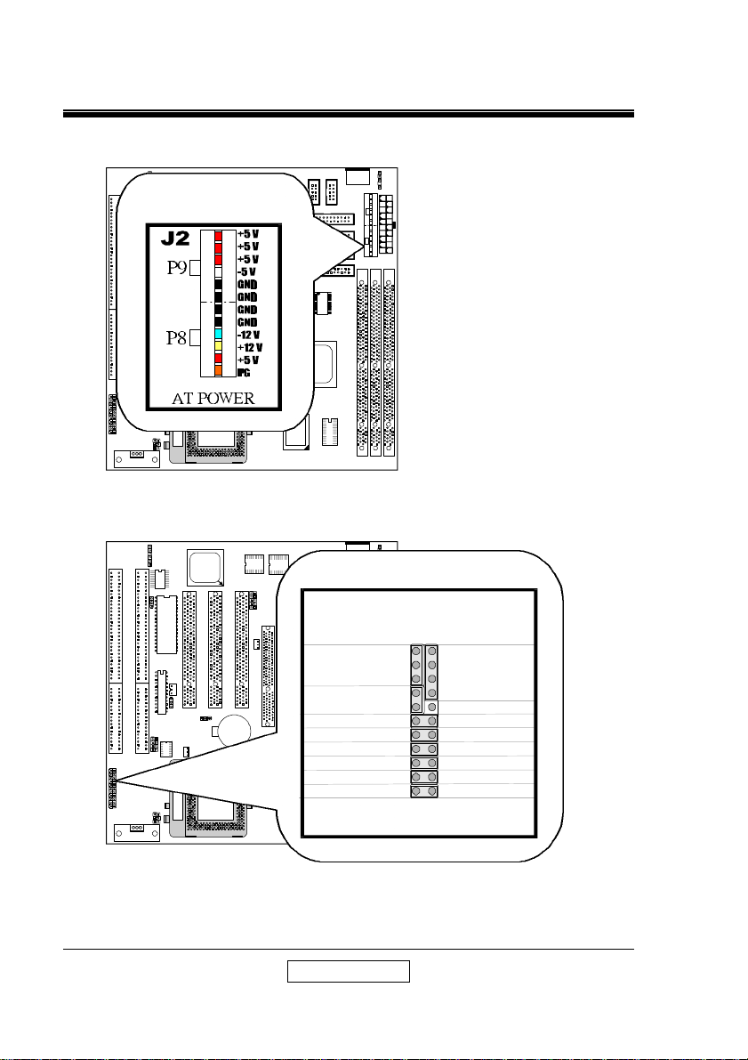
9. AT POWER SUPPLY CONNECTOR(J2).……………………..………..…………9
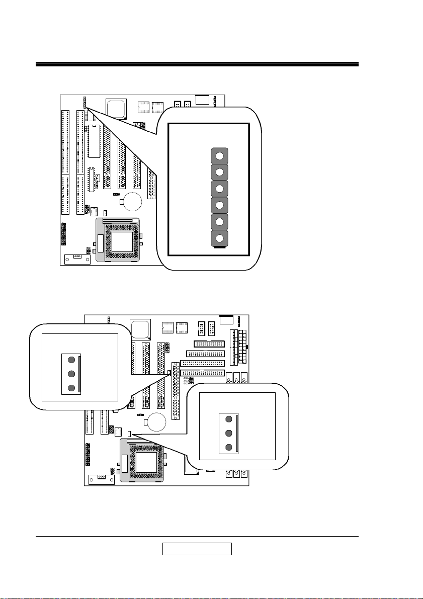
10. SYSTEM PANEL CONNECTORS(CN6)………………….………..……..……….9
11. IR CONNECTOR (FIR1) …..……………………………..……………...………...10
12. FAN CONNECTORS ( FAN1, FAN2)……….……………………………...……..10
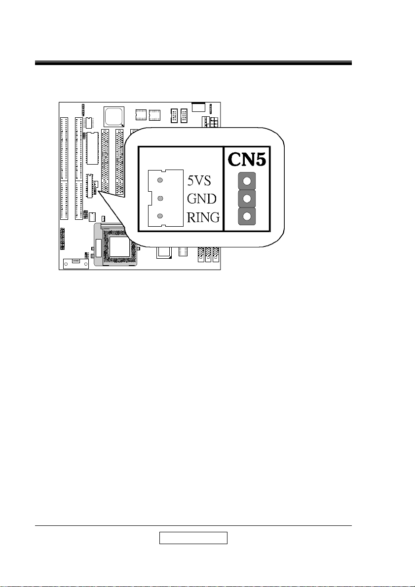
13. LAN WAKE-UP CONNECTORS (CN4, CN5)…………………..………………..11
BIOS SETTING
INTRODUCTION ……………………………………….……….………………....……12
MAIN MENU……………….…………………………………....…………….………….15
STANDARD CMOS SETUP….………..………………….………………………….…18
BIOS FEATURES SETUP.………………………………..…………………..………...22
INTEGTATED PERIPHERALS FEATURES SETUP.…....………...……….………..27
SUPERVISOR/USER PASSWORD SETTING……….……………………….……...30
CHIPSET FEATURES SETUP.…………………………………………...……………31
POWER MANAGEMENT SETUP…………………………………………….……….35
PNP/PCI CONFIGURATION SETUP………………...…………………….………….39
LOAD BIOS DEFAULTS.…………………………………………………….………….43
LOAD SETUP DEFAULTS..…………………………...……………………….……….44
SAVE AND EXIT SETUP………………………..……………………….……………..45
LOW – LEVEL FORMAT UTILITY...……………………………...……….…………...46
UPGRADE BIOS…………………………………………………………………………48
User’ s Manual
Rev.1.1
Page 2

SETUP GUIDE
1
MAIN BOARD FEATURE INTRODUCTION
SPECIFICATIONS
Chipset
SUPER I/O
CPU Support
CPU Host Clock
From Factor
BIOS Vendor
Voltage
CACHE
Memory
ISA
PCI
Slots
AGP
I/O
Other
Dimension
New Function
ALI – V M1542
ALI M1543
One321-pin Socket 7 for INTEL P54C/MMX, AMD K5/
K6/K6-2, CYRIX 6x86/L/M2 and WINCHIP IDT C6
Processors
60 , 66 , 75 , 83.3 , 95 , 100 MHz
AT
AWARD GREEN , Plug & Play
2.0V ~ 3.5V
On board PBSRAM 64K x 64 (512K)
Three 168-pin DIMMs [support FPM/EDO(3.3V)/
SDRAM(support PC-100MHz)]
Two 16-Bit ISA
Three 32-Bit PCI
One AGP(Accelerated Graphics Port) for high
performance, component level interconnect targeted at
3D graphical display application
1. Two high speed 16550 compatible serial ports.
2. One Multi-Mode Parallel port fixed (SPP/EPP/ECP
standard).
3. Two Universal Serial Bus ports (USB).
4. Keyboard and PS/2 mouse.
5. Two IDE ports ,supports four IDE devices (PIO mode
4, DMA mode 2, Ultra DMA 33), and LS-120/ZIP disk
driver
6. Two720KB/1.2MB/1.44MB/2.88MB Floppy disk
controller.
1. Auto Temperature Sensor Monitor & Music Alarm
(OPTION).
2. CPU FAN control in Suspend ON/OFF .
3. LAN wake-up . Modem Ring wake-up .
Four-Layer PCB , AT size ( 220mm X 230mm )
Trend ChipAwayVirus In BIOS & Pc-cillin 95 in diskette
User’ s Manual
Page 3

SETUP GUIDE
2
MAINBOARD LAYOUT DRAWING:
User’ s Manual
Page 4

SETUP GUIDE
3
MEMORY INSTALLATION
Three by 168-pin DIMM sockets (DIMM1, DIMM2,DIMM3) to support 8MB,
16MB, 32MB, 64MB, 128MB or 256MB to from a memory size between 8MB to
768MB , support FAST PAGE MODE (FPM) , EXTENDED DATA OUTPUT
(EDO/3.3V) and SYNCHRONOUS DYNAMIC RANDOM ACCESS MEMORY
(SDRAM/PC-100MHz) DIMMs .
User’ s Manual
Page 5

SETUP GUIDE
4
CPU QUICK INSTALLED TABLE
INTEL CPU
P (MMX) – 266MHz
P (MMX) – 233MHz
P (MMX) – 200MHz
P (MMX) – 166MHz
PENTIUM – 200MHz
PENTIUM – 166MHz
PENTIUM – 150MHz
PENTIUM – 133MHz
AMD CPU
K6 – 2/350MHz
K6 – 2/333MHz
K6 – 2/300MHz
K6 – 2/266MHz
K6 – 2/250MHz
K6 – 300MHz
K6 - 266MHz
K6 – 233MHz
K6 – 200MHz
K6 – 166MHz
À
Á
À
À
CYRIX CPU
6x86M¢º – 300MHz
6x86M¢º – 233MHz
6x86M¢º – 200MHz
6x86M¢º – 200MHz
6x86M¢º – 166MHz
6x86L – P200 (150MHz)
6x86L – P166 (133MHz)
6x86L – P150 (120MHz)
Note : O – OPEN S – SHORT
For AMD K6-300MHz JV2:OPEN (3.45V).
À : 100MHz Á : 95MHz
* This “CPU Quick INSTALLED TABLE” at present market condition, thereafter
new CPU installed, please reference material CPU or write on CPU setting speak.
CPU CLK
JC1 JC2 JC3 1-2 3-4 5-6 1-2 3-4 5-6 7-8
O S S S O S O O O S
O S S O O O O O O S
O S S O S O O O O S
O S S S S O O O O S
O S S O S O O S S S
O S S S S O O S S S
S S S S S O O S S S
O S S S O O O S S S
CPU CLK
JC1 JC2 JC3 1-2 3-4 5-6 1-2 3-4 5-6 7-8
O O O O O O O S O O
S O O O O O O S O O
O O O O S O O S O O
O S S S O S O S O O
O O O S S O O S O O
O S S S S S O S O O
O S S S O S O S O O
O S S O O O O S O O
O S S O S O S O O S
O S S S S O S O O S
CPU CLK
JC1 JC2 JC3 1-2 3-4 5-6 1-2 3-4 5-6 7-8
S S O O S O S O O S
S S O S S O S O O S
S S O S O O O O O S
O S S S S O S O O S
O S S S O O S O O S
S S O S O O O O O S
O S S S O O O O O S
S S S S O O O O O S
CPU RATIO
(JB1)
CPU RATIO
(JB1)
CPU RATIO
(JB1)
CPU VOLT
(JV1)
CPU VOLT
(JV1)
CPU VOLT
(JV1)
User’ s Manual
Page 6
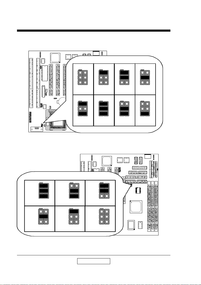
SETUP GUIDE
5
1
JR1
TAG
CACHE
CLK
AT POWER
1
1
2
1
2
1
2
1
2
CN1
J1
CN3
DIMM1
DIMM2
DIMM3
USB
M1542
A586B REV A
JC1
JC2
JC3
100 MHz
95 MHz
2
4
6
JC1
JC2
JC3
75 MHz
JC1
JC2
JC3
75 MHz
1
3
5
2
4
6
JB1
x 5.0
x 4.5
1
3
5
2
4
6
JB1
x 3.0
1
3
5
2
4
6
JB1
x 2.5
1
3
5
2
4
6
JB1
x 5.5
JUMPER SETTING
1. CPU TO BUS FREQUENCY RATIO JUMPER SETTING (JB1) :
FIR1
ALi
M1543
COM2
COM1
2
1
1
CN1
CN3
2
JB1
1
2
4
6
2
3
4
5
6
x 2.0
JB1
1
2
4
6
2
3
4
5
6
CN6
BIOS
CN4
CN5
JV1
ISA1ISA2
JB1
PCI2
PCI3
JBT1
+
FAN2
JB1
1
3
5
x 1.5 /
x 3.5
JB1
1
3
5
x 4.0
2. CPU CLOCK JUMPER SETTING (JC1,JC2,JC3) :
FIR1
ALi
M1543
JC1
JC2
JC3
60 MHz
JC1
JC1
JC2
JC2
JC3
JC3
83 MHz
JC1
JC2
JC3
66 MHz
JC1
JC2
JC3
COM2
COM1
2
1
2
1
J2
LPT
FDD
IDE2
IDE1
ALi
User’ s Manual
Page 7
SETUP GUIDE
6
TAG
CACHE
SOCKET 7
1
JV1
M1542
A586B REV A
TAG
CACHE
SOCKET 7
JR1
JV1
J1
A586B REV A
3.45V
1
3
5
7
2
4
6
8
JV1
3.5V
1
3
5
7
2
4
6
8
JV1
3.3V
1
3
5
7
2
4
6
8
JV1
1
3
5
7
2
4
6
8
JV1
1
3
5
7
2
4
6
8
JV1
1
3
5
7
2
4
6
8
JV1
1
3
5
7
2
4
6
8
JV1
1
3
5
7
2
4
6
8
JV1
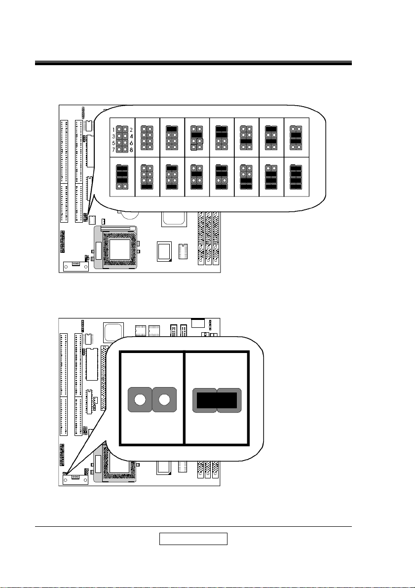
3. CPU VOLTAGE JUMPER SETTING 1 (JV1) :
JV1
JV1
JV1
JV1
1
2
3
4
5
6
7
8
2.0V
JV1
JV1
1
2
3
4
5
6
7
8
2.8V
2
4
6
8
CN6
ISA1ISA2
JB1
1
3
5
7
2.7V
4. CPU VOLTAGE JUMPER SETTING 2(JV2) :
1
1
3
5
7
2.1V
JV1
1
3
5
7
2.9V
2
2
3
4
4
5
6
6
7
8
8
2.2V
JV1
1
2
2
3
4
4
5
6
6
7
8
8
3.0V
2.3V
3.1V
2.5V
2.4V
3.2V
2.6V
FIR1
ALi
M1543
BIOS
JV2 JV2
CN4
CN5
ISA1ISA2
CN6
JB1
JV2
COM2
COM1
CN3
2
1
2
1
J2
3.3V
User’ s Manual
CN1
Page 8
SETUP GUIDE
7
SOCKET 7
1
JR1
A586B REV A
JR1
TAG
CACHE
CLK
SOCKET 7
AT POWER
1
1
2
1
2
1
2
1
2
JR1
CN1
J1
CN3
DIMM1
DIMM2
DIMM3
FAN1
USB
M1542
A586B REV A
NORMAL
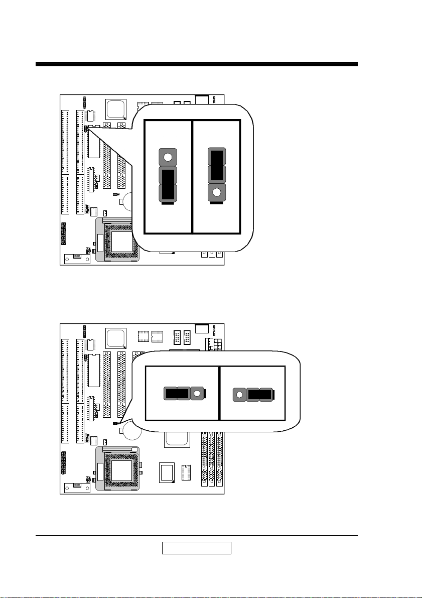
5. BIOS VOLTAGE JUMPER SETTING (JR1) :
FIR1
ALi
M1543
JR1
CN4
PCI3
CN5
JBT1
JV1
ISA1ISA2
CN6
JB1
6. CMOS CLEAR (JBT1) :
FIR1
+
FAN2
ALi
M1543
BIOS
COM2
COM1
2
1
5V
COM2
COM1
2
1
LPT
FDD
IDE2
IDE1
JBT1
CN1
CN3
2
1
12V
2
1
J2
JBT1
CN4
CN5
JV1
ISA2
ISA1
CN6
JB1
PCI2
PCI3
PCI1
JBT1
+
FAN2
CMOS Clear
BAT
AGP
ALi
User’ s Manual
Page 9
SETUP GUIDE
8
TAG
CACHE
CLK
SOCKET 7
AT POWER
1
1
2
1
2
1
2
1
2
JR1
CN1
J1
CN3
DIMM1
DIMM2
DIMM3
FAN1
USB
M1542
A586B REV A
TAG
CACHE
CLK
SOCKET 7
AT POWER
1
1
2
1
2
1
2
1
2
JR1
CN1
J1
CN3
DIMM1
DIMM2
DIMM3
FAN1
USB
M1542
A586B REV A
1
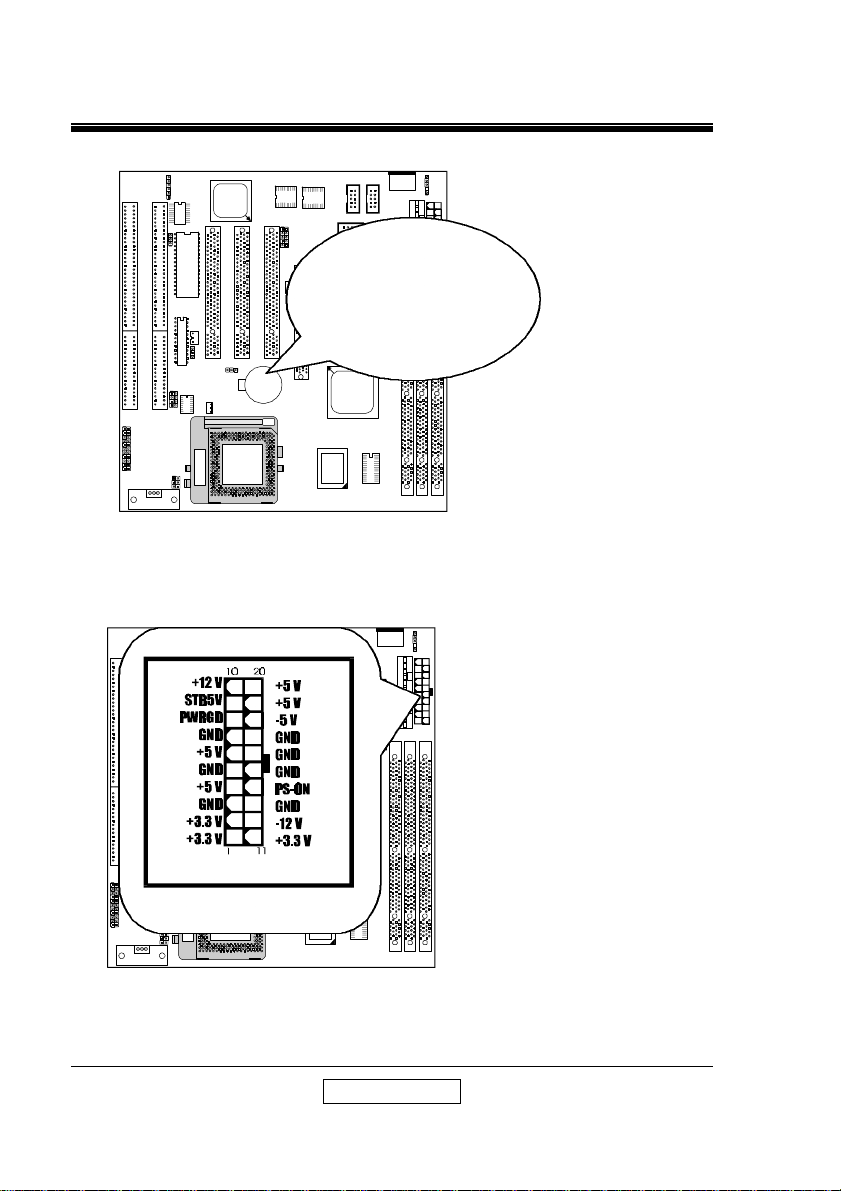
7. BATTERY :
FIR1
ALi
M1543
BIOS
ISA2
CN4
CN5
JV1
ISA1
CN6
JB1
PCI2
PCI3
PCI1
JBT1
BAT
+
FAN2
AGP
8. ATX POWER SUPPLY CONNECTOR (J1) :
FIR1
ALi
M1543
BIOS
FDD
IDE2
IDE1
COM2
COM1
2
1
2
1
J2
LPT
FDD
IDE2
BATTERY
IDE1
CR2032 3V
LITHIUM CELL
ALi
COM2
COM1
2
1
2
1
J2
J1
LPT
CN4
CN5
JV1
ISA2
CN6
FAN2
ISA1
ATX POWER
JB1
PCI3
JBT1
PCI2
PCI1
BAT
+
AGP
ALi
User’ s Manual
Page 10
SETUP GUIDE
9
TAG
CACHE
CLK
SOCKET 7
AT POWER
1
1
2
1
2
1
2
1
2
JR1
CN1
J1
CN3
DIMM1
DIMM2
DIMM3
FAN1
USB
M1542
A586B REV A
TAG
CACHE
CLK
SOCKET 7
AT POWER
1
1
2
1
2
1
2
1
2
JR1
CN1
J1
CN3
DIMM1
DIMM2
DIMM3
FAN1
USB
M1542
A586B REV A
SPEAKER
+HDD LED
+SMI LED
HDD LED-
SMI LED-
LED
1 22
11 12
9. AT POWER SUPPLY CONNECTOR (J2) :
FIR1
ALi
M1543
BIOS
CN4
PCI3
CN5
JBT1
JV1
FAN2
ISA1ISA2
CN6
JB1
PCI2
PCI1
BAT
+
AGP
COM2
COM1
2
1
2
1
LPT
FDD
IDE2
IDE1
ALi
10. SYSTEM PANEL CONNECTORS (CN6) :
FIR1
ALi
M1543
BIOS
COM2
COM1
2
1
2
1
LPT
FDD
IDE2
CN6
IDE1
POWER
CN4
CN5
JV1
ISA2
ISA1
CN6
JB1
PCI2
PCI3
PCI1
JBT1
BAT
+
FAN2
AGP
KEY LOCK
ALi
SMI SW
RESET
TB LED-
J2
J2
PS-ON
+
+5V
GND
GND
+TB LED
+3VSB
User’ s Manual
Page 11
SETUP GUIDE
10
SOCKET 7
AT POWER
1
1
2
1
2
1
2
1
2
CN1
J1
CN3
DIMM1
DIMM2
DIMM3
FAN1
USB
A586B REV A
SOCKET 7
JR1
USB
GND
12V
GND
AGP FAN
GND
12V
GND
CPU FAN
FIR1
IRTX
IRRX
11. IR CONNECTOR (FIR1) :
FIR1
ALi
M1543
COM2
COM1
2
1
1
CN1
CN3
2
BIOS
CN4
CN5
JV1
ISA2
ISA1
CN6
JB1
PCI2
PCI3
PCI1
JBT1
BAT
+
FAN2
GND
5V
1
12. FAN CONNECTORS (CPU FAN2, AGP FAN1) :
FIR1
ALi
M1543
COM2
COM1
212
1
J2
LPT
FDD
IDE2
IDE1
ISA1ISA2
CN6
PCI2
PCI1
JBT1
BAT
+
JV1
FAN2
JB1
AGP
User’ s Manual
Page 12
SETUP GUIDE
11
TAG
CACHE
CLK
SOCKET 7
AT POWER
1
1
2
1
2
1
2
1
2
JR1
CN1
J1
CN3
DIMM1
DIMM2
DIMM3
FAN1
USB
M1542
A586B REV A
CN4
13. LAN WAKE-UP CONNECTOR (CN4 or CN5) :
FIR1
BIOS
CN4
CN5
JV1
ISA2
CN6
FAN2
ISA1
JB1
ALi
M1543
PCI2
PCI3
PCI1
JBT1
BAT
+
AGP
COM2
COM1
2
1
2
1
J2
LPT
FDD
IDE2
IDE1
ALi
LAN Wake-up require 5V stand-by voltage > 600mA for your ATX power.
User’ s Manual
Page 13

SETUP GUIDE
12
BIOS SETTING
Introduction
This manual discusses Award's Setup program built into the ROM BIOS. The
Setup program allows users to modify the basic system configuration. This
special information is then stored in battery back-up RAM so that it retains the
Setup information when the power is turned off.
The Award BIOS installed in your computer system ROM (Read Only Memory) is
a custom version of an industry standard BIOS. This means that it supports
Intel/Cyrix/AMD/ C6 processors in a standard IBM-AT compatible input/output
system. The BIOS provides critical low-level support for standard devices such
as disk drives, serial and parallel ports.
The Award BIOS has been customized by adding important, but non-standard,
features such as virus and password protection as well as special support for
detailed fine-tuning of the chipset controlling the entire system.
The rest of this manual is intended to guide you through the process of
configuring your system using Setup.
Starting Setup
The Award BIOS is immediately activated when you first power on the computer.
The BIOS reads the system information contained in the CMOS and begins the
process of checking out the system and configuring it. When it finishes, the
BIOS will seek an operating system on one of the disks and then launch and turn
control over to the operating system.
While the BIOS is in control, the Setup program can be activated in one of two
ways:
1. By pressing <Del> immediately after switching the system on, or
2. by pressing the <Del> key when the following message appears briefly at the
bottom of the screen during the POST (Power On Self Test).
Press <DEL> to enter SETUP.
If the message disappears before you respond and you still wish to enter Setup,
restart the system to try again by turning it OFF then ON or pressing the "RESET"
button on the system case. You may also restart by simultaneously pressing
User’ s Manual
Page 14

SETUP GUIDE
13
<Ctrl>, <Alt>, and <Delete> keys. If you do not press the keys at the correct
time and the system does not boot, an error message will be displayed and you
will again be asked to...
PRESS <F1> TO CONTINUE, <DEL> TO ENTER SETUP
Using Setup
In general, you use the arrow keys to highlight items, press <Enter> to select, use
the PageUp and PageDown keys to change entries, press <F1> for help and
press <Esc> to quit. The following table provides more detail about how to
navigate in the Setup program using the keyboard.
Up arrow Move to previous item
Down
arrow
Left arrow Move to the item in the left hand
Right
arrow
Esc key Main Menu -- Quit and not save changes into CMOS
PgUp key Increase the numeric value or make changes
PgDn key Decrease the numeric value or make changes
+ key Increase the numeric value or make changes
- key Decrease the numeric value or make changes
F1 key General help, only for Status Page Setup Menu and Option Page Setup
(Shift)F2
key
F3 key Calendar, only for Status Page Setup Menu
F4 key Reserved
F5 key Restore the previous CMOS value from CMOS, only for Option Page
F6 key Load the default CMOS value from BIOS default table, only for Option
F7 key Load the default
F8 key Reserved
F9 key Reserved
F10 key Save all the CMOS changes, only for Main Menu
Move to next item
Move to the item in the right hand
Status Page Setup Menu and Option Page Setup Menu -- Exit current page
and return to Main Menu
Menu
Change color from total 16 colors. F2 to select color forward, (Shift) F2
to select color backward
Setup Menu
Page Setup Menu
User’ s Manual
Page 15

SETUP GUIDE
14
Getting Help
Press <F1> to pop up a small help window that describes the appropriate keys to
use and the possible selections for the highlighted item. To exit the Help
Window press <Esc> or the <F1> key again.
In Case of Problems
If, after making and saving system changes with Setup, you discover that your
computer no longer is able to boot, the Award BIOS supports an override to the
CMOS settings which resets your system to its defaults.
The best advice is to only alter settings which you thoroughly understand. To
this end, we strongly recommend that you avoid making any changes to the
chipset defaults. These defaults have been carefully chosen by both Award and
your systems manufacturer to provide the absolute maximum performance and
reliability. Even a seemingly small change to the chipset setup has the potential
for causing you to use the override.
A Final Note About Setup
Not all systems have the same Setup. While the basic look and function of the
Setup program remains the same for all systems, individual motherboard and
chipset combinations require custom configurations. For example, you may find
that your Setup main menu has a different number of entries from the main menu
displayed in this manual. These are simply features not supported (or not user
configurable) on your system.
The final appearance of the Setup program also depends on the Original
Equipment Manufacturer (OEM) who built your system. If your OEM has
decided that certain items should only be available to their technicians, those
items may very well be removed from the Setup program.
User’ s Manual
Page 16

SETUP GUIDE
15
1. MAIN MENU
Once you enter the Award BIOS CMOS Setup Utility, the Main Menu will appear
on the screen. The Main Menu allows you to select from several setup functions
and two exit choices. Use the arrow keys to select among the items and press
<Enter> to accept and enter the sub-menu.
ROM PCI / ISA BIOS
CMOS SETUP UTILITY
AWARD SOFTWARE, INC.
STANDARD CMOS SETUP
INTEGRATED PERIPHERALS
BIOS FEATURES SETUP
CHIPSET FEATURES SETUP
POWER MANAGEMENT SETUP
PNP//PCI CONFIGURATION
LOAD BIOS DEFAULTS
LOAD SETUP DEFAULTS
Esc : Quit áâàß : Select Item
F10 : Save & Exit setup (Shift)F2 : Change Color
Virus Protection, Boot Sequence….
SUPERVISOR PASSWORD
USER PASSWORD
IDE HDD AUTO DETECTION
SAVE & EXIT SETUP
EXIT WITHOUT SAVING
Note that a brief description of each highlighted selection appears at the bottom
of the screen.
Setup Items
The main menu includes the following main setup categories. Recall
that some systems may not include all entries.
User’ s Manual
Page 17

16
Standard CMOS
Setup
SETUP GUIDE
This setup page includes all the items in a standard,
AT-compatible BIOS.
BIOS FEATURES
SETUP
Super / User
Password Setting
Chipset Features
Setup
Power
Management Setup
PNP / PCI
Configuration
Setup
Load BIOS
Defaults
Load Setup
Defaults
This setup page includes all the items of Award special
enhanced features.
Change, set, or disable password. It allows you to
limit access to the system and Setup, or just to Setup.
This setup page includes all the items of chipset special
features.
This entry only appears if your system supports Power
Management, ”Green PC”, standards.
This entry appears if your system supports PNP /
PCI.
The BIOS defaults have been set by the manufacturer
and represent settings which provide the minimum
requirements for your system to operate.
The chipset defaults are settings which provide for
maximum system performance. While Award has
designed the custom BIOS to maximize performance,
the manufacturer has the right to change these defaults
to meet their needs.
Integrated
Peripherals
This section page includes all the items of IDE
hard drive and Programmed Input / Output
features.
User’ s Manual
Page 18

17
IDE HDD Auto
Detection
SETUP GUIDE
Automatically detect and configure hard disk
parameters. The Award BIOS includes this ability in
the event you are uncertain of your hard disk
parameters.
HDD Low Level
Format
Save & Exit Setup
Exit Without Save
If supported by your system, this provides a hard disk
low level format utility.
Save CMOS value changes to CMOS and exit setup.
Abandon all CMOS value changes and exit setup.
User’ s Manual
Page 19

SETUP GUIDE
18
Secondary Master
: Auto 0 0 0 0 0 0 Auto
: Auto 0 0 0 0 0 0 Auto
2. STANDARD CMOS SETUP
The items in Standard CMOS Setup Menu are divided into 10 categories. Each
category includes no, one or more than one setup items. Use the arrow keys to
highlight the item and then use the <PgUp> or <PgDn> keys to select the value
you want in each item.
ROM PCI / ISA BIOS
STANDARD CMOS SETUP
AWARD SOFTWARE, INC.
Date (mm:dd:yy) : Wed, Jul, 29, 1998/7/29
Time (hh:mm:ss) : 9 : 25 : 5
HARD DISK TYPE SIZE CYLS HEAD PRECOMP LANDZ SECTOR MODE
Primary Master
Primary Slave
Secondary Slave
Drive A : 1.44M, 3.5in.
Drive B : None
Video : EGA/VGA
Halt On : All Errors
: Auto 0 0 0 0 0 0 Auto
: Auto 0 0 0 0 0 0 Auto
Base Memory : 640K
Extended Memory : 261120K
Other Memory : 384K
___________________________
Total Memory : 262144K
Ecs : Quit áâàß : Select Item PU/PD/+/- : Modify
F1 : Help (Shift)F2 : Change Color
DATE
The date format is <day>, <date> <month> <year>.
Press <F3> to show the calendar.
day
date The date, from 1 to 31 (or the maximum
month The month, Jan through Dec.
year The year, from 1994 through 2079
The day, from Sun to Sat, determined by
the BIOS and is display-only
allowed in the month)
User’ s Manual
Page 20

19
TIME
SETUP GUIDE
The time format is <hour> <minute> <second>.
The time is calculated based on the 24-hour
military-time clock. For example, 1 p.m. is
13:00:00.
DAYLIGHT
SAVING
The category adds one hour to the clock when
daylight-saving time begins. It also subtracts one hour
when standard time returns.
Enabled Enable daylight-saving
Disabled Disable daylight-saving
User’ s Manual
Page 21

20
Primary
Master/Primary
Slave/Secondary
Master/Secondary
Slave
Drive A Type /
Drive B Type
SETUP GUIDE
The categories identify the types of 2 channels that
have been installed in the computer. There are 45
predefined types and 4 user definable types are for
Enhanced IDE BIOS. Type 1 to Type 45 are
predefined. Type user is user-definable.
Press PgUp or PgDn to select a numbered hard disk
type or type the number and press <Enter>. Note
that the specifications of your drive must match with the
drive table. The hard disk will not work properly if you
enter improper information for this category. If your
hard disk drive type is not matched or listed, you can
use Type ”User” to define your own drive type
manually.
If you select Type ”User”, you will need to know the
information listed below. Enter the information directly
from the keyboard and press <Enter>. This
information should be included in the documentation
from your hard disk vendor or the system manufacturer.
If the controller of HDD interface is ESDI, the selection
shall be ”Type 1”.
If the controller of HDD interface is SCSI, the selection
shall be ”None”.
If you select Type ”Auto”, BIOS will Auto-Detect the
HDD & CD-ROM Drive at the POST stage and showing
the IDE for HDD & CD-ROM Drive.
TYPE drive type
CYLS. number of cylinders
HEADS number of heads
PRECOMP write precom
LANDZONE landing zone
SECTORS number of sectors
MODE mode type
If a hard disk has not been installed select NONE
and press <Enter>.
The category identifies the types of floppy disk drive A
or drive B that have been installed in the computer.
The choice: None, 360K(5.25in), 1.2M(5.25in),
720K(3.5in), 1.44M(3.5in), 2.88M(3.5in) .
User’ s Manual
Page 22

21
VIDEO
SETUP GUIDE
The category selects the type of video adapter used for
the primary system monitor. Although secondary
monitors are supported, you do not have to select the
type in Setup.
The choice: EGA/VGA, CGA 40, CGA 80, MONO .
HALT ON
MEMORY
The category determines whether the computer will
stop if an error is detected during power up.
The choice: No errors, All errors; All, But Keyboard;
All, But Diskette; All, But Disk/Key .
The category is display-only which is determined by
POST (Power On Self Test) of the BIOS.
Base Memory
The POST will determine the amount of base (or
conventional) memory installed in the system. The
value of the base memory is typically 512K for systems
with 512K memory installed on the motherboard, or
640K for systems with 640K or more memory installed
on the motherboard.
Extended Memory
The BIOS determines how much extended memory is
present during the POST. This is the amount of
memory located above 1MB in the CPU's memory
address map.
Other Memory
This refers to the memory located in the 640K to 1024K
address space. This is memory that can be used for
different applications. DOS uses this area to load
device drivers in an effort to keep as much base
memory free for application programs. The BIOS is
the most frequent user of this RAM area since this is
where it shadows RAM
User’ s Manual
Page 23

SETUP GUIDE
22
3. BIOS FEATURES SETUP
This section allows you to configure your system for basic operation. You
have the opportunity to select the system default speed, boot-up sequence,
keyboard operation, shadowing and security.
ROM PCI / ISA BIOS
STANDARD CMOS SETUP
AWARD SOFTWARE, INC.
ChipAwayVirus on Guard
CPU Internal Cache
External cache
Quick Power On Self Test
Boot Sequence
Swap Floppy Drive
Boot Up Floppy Seek
Boot Up Numlock Status
Gate A20 Option
Typematic Rate Setting
Typematic Rate (Chars/Sec)
Typematic Delay (Msec)
Security Option
IDE Second Channel Control
PS/2 mouse function control
PCI/VGA Palette Snoop
OS Select For DRAM > 64MB
Report No FDD For WIN 95
: Enabled
: Enabled
: Enabled
: Enabled
: A, C, SCSI
: Disabled
: Enabled
: On
: Fast
: Disabled
: 6
: 250
: Setup
: Disabled
: Disabled
: Disabled
: Non-OS2
: No
Video BIOS Shadow
C8000-CBFFF Shadow
CC000-CFFFF Shadow
D0000-D3FFF Shadow
D4000-D7FFF Shadow
D8000-DBFFF Shadow
DC000-DFFFF Shadow
Esc : Quit áâàß : Select Item
F1 : Help PU/PD/+/- : Modify
F5 : Old Values (Shift)F2 : Color
F6 : Load BIOS Defaults
F7 : Load Setup Defaults
: Enabled
: Disabled
: Disabled
: Disabled
: Disabled
: Disabled
: Disabled
User’ s Manual
Page 24

23
ChipAwayVirus on
Guard
SETUP GUIDE
When this item is Trend ChipAwayVirus (TCAV) on
Guard. Boot Viruses pose the most severe threat
because they can move from a floppy diskette to your
hard drive in less then a second. And it all happens
during the loading of the boot sector. Provides a virusfree boot and operating system, experience peace of
mind though hardware-base virus protection, detects
known and unknown boot viruses with rule-based
technology, receive immediate protection! Already
installed on this board!.
The Choice: Enabled, Disabled .
CPU Internal
Cache/External
Cache
Quick Power On
Self Test
Boot Sequence
These two categories speeds up memory access.
However, it depends on CPU /Chipset design. The
default value is enable.
The Choice: Enabled, Disabled .
This category speeds up Power On Self Test (POST)
after you power up the computer. If it is set to Enable,
BIOS will shorten or skip some check items during
POST.
The Choice: Enabled, Disabled .
This category determines which driver to search first for
the disk operating system (i.e.,DOS). Default value is
A,C.
The Choice: A,C,SCSI ; C,A,SCSI ; C,CDROM,A ;
CDROM,C,A ; D,A,SCSI ; SCSI,A,C ; SCSI,C,A ; C
only ; LS/ZIP,C .
User’ s Manual
Page 25

24
Swap Floppy
Driver
SETUP GUIDE
This item allows you to determine whether enable the
swap floppy driver or not.
The Choice: Enabled, Disabled .
Boot up Floppy
Seek
Boot Up NumLock
Status
Boot Up System
Speed
Gate A20 Option
During POST , BIOS will determine if the floppy disk
driver installed is 40 or 80 tracks. 360K type is 40
tracks while 720K, 1.2M and 1.44M are all 80 tracks.
The Choice: Enabled, Disabled .
This allows you to determine the default status of the
numeric keypad. By default, the system boots up with
NumLock on .
The Choice: On , Off .
Selects the default system speed – the normal
operating speed at power up.
The Choice: High , Low .
This entry allows you to select how the gate A20 is
handled. The gate A20 is a device used to address
memory above 1 Mbytes. Initially, the gate A20 was
handled via a pin on the keyboard. Today, while
keyboards still provide this support, it is more common,
and much faster, for the system chipset to provide
support for gate A20.
The Choice: Normal , Fast .
User’ s Manual
Page 26

25
Typematic Rate
Setting
SETUP GUIDE
This determines if the typematic rate is to be used.
When disabled, con-tinually holding down a key on
your keyboard will generate only one instance. In other
words, the BIOS will only report that the key is down.
When the typematic rate is enabled, the BIOS will
report as before, but it will then wait a moment, and, if
the key is still down, it will begin the report that the key
has been depressed repeatedly. For example, you
would use such a feature to accelerate cursor
movements with the arrow keys.
The Choice: Enabled, Disabled .
Typematic Rate
(Chars/Sec)
Typematic Delay
(Msec)
Security Option
When the typematic rate is enabled, this selection
allows you select the rate at which the keys are
accelerated.
The Choice: 6, 8, 10, 12, 15, 20, 24, 30 .
When the typematic rate is enabled, this selection
allows you to select the delay between when the key
was depressed and when the acceleration begins .
The Choice: 250, 500, 750, 1000 .
This category allows you to limit access to the system
and setup, or just to setup .
The Choice: System, Setup .
Note: To disable security, select PASSWORD
SETTING at Main Menu and then you will be asked to
enter password. Do not type anything and just press
<Enter>, it will disable security. Once the security is
disabled, the system will boot and you can enter setup
freely .
User’ s Manual
Page 27

26
OS Select for
DRAM > 64MB
SETUP GUIDE
This item allows you to access the memory that over
64MB in OS/2 .
The Choice: Non-OS2 , OS2 .
PCI / VGA Palette
Snoop
Video BIOS
Shadow
C8000 – CBFFF
Shadow / DC000 –
DFFFF Shadow
It determines whether the MPEG ISA / VESA VGA
Cards can work with PCI / VGA or not .
The Choice: Enabled, Disabled .
Determines whether video BIOS will be copied to RAM.
However, it is op-tional depending on chipset design.
Video Shadow will increase the video speed .
The Choice: Enabled, Disabled .
These categories determine whether option ROMs will
be copied to RAM. An example of such option ROM
would be support of on-board SCSI.
The Choice: Enabled, Disabled .
User’ s Manual
Page 28

SETUP GUIDE
27
4. INTEGRATED PERIPHERALS :
ROM PCI / ISA BIOS
INTEGRATED PERIPHERALS
AWARD SOFTWARE, INC.
On-Chip Primary IDE
Master PIO
Slave PIO
Master Ultra DMA
Slave Ultra DMA
On-Chip Secondary IDE
Master PIO
Slave PIO
Master Ultra DMA
Slave Ultra DMA
IDE HDD Block Mode
On-Chip USB Controller
: Enabled
: Auto
: Auto
: Auto
: Auto
: Enabled
: Auto
: Auto
: Auto
: Auto
: Enabled
: Disabled
Onboard FDC Controller
Onboard Serial Port 1
Onboard Serial Port 2
UR2 Mode
Onboard Parallel Port
Parallel Port Mode
: Enabled
: 3F8/IRQ4
: 2F8/IRQ3
: Normal
: 378/IRQ7
: SPP
Init Display First
Ring/Wake On LAN Control
RTC Alarm Controller
On-Chip First
Channel
On-Chip Second
Channel
: PCI Slot
: Disabled
: Disabled
Esc : Quit áâàß : Select Item
F1 : Help PU/PD/+/- : Modify
F5 : Old Values (Shift)F2 : Color
F6 : Load BIOS Defaults
F7 : Load Setup Defaults
This chipset contains a PCI IDE interface with support
for two IDE channels. Select Enabled to activate the
first and/or second IDE interface. Select Disabled to
deactivate this interface, if you install a first and/or
second add-in IDE interface IDE interface.
The choice: Enabled, Disabled.
This chipset contains a PCI IDE interface with support
for two IDE channels. Select Enabled to activate the
first and/or second IDE interface. Select Disabled to
deactivate this interface, if you install a first and/or
second add-in IDE interface IDE interface.
The choice: Enabled, Disabled.
User’ s Manual
Page 29

28
IDE HDD Block
Mode
SETUP GUIDE
This item allows your hard disk controller to use the fast
block mode to transfer data to and from your hard disk
drive (HDD). Select Enabled only if your hard drives
support block mode.
The choice: Enabled, Disabled.
IDE Primary/
Secondary Master/
Slave PIO
IDE Primary/
Secondary Master/
Slave UDMA
Onboard FDD
Controller
Onboard Serial
Port 1/Port 2
The four IDE PIO (Programmed Input/ Output) fields let
you set a PIO mode
(0-4) for each of the four IDE devices that the onboard
IDE interface supports.
Modes 0 through 4 provide successively increased
performance. In Auto mode, the system automatically
determines the best mode for each device.
Ultra DMA/33 implementation is possible only if your
IDE hard drive supports it and the operating
environment includes a DMA driver (Windows 95
OSR2 or a third-party IDE bus master driver). If your
hard drive and your system software both support Ultra
DMA/33, select Auto to enable BIOS support.
The Choice: Auto, Disabled
This should be enabled if your system has a floppy disk
drive (FDD) installed on the system board and you wish
to use it. Even when so equipped, if you add a higher
performance controller, you will need to disable this
feature.
The choice: Enabled, Disabled.
This item allows you to determine access onboard
serial port 1/port 2 controller with I/O address.
The choice: 3F8/IRQ4, 2E8/IRQ3, 3E8/IRQ4,
2F8/IRQ3, Disabled.
UART 2 Mode
This item allows you to determine which Infra Red (IR)
function of onboard I/O chip.
The choice: Normal, ASK IR, IrDA.
User’ s Manual
Page 30

29
IR Function
Duplex
SETUP GUIDE
This item allows you to select the IR function when you
select the UART 2 Mode is ASKIR
The choice: Half, Full.
Onboard Parallel
Port
Onboard Parallel
Mode
ECP Mode Use
DMA
Parallel Port EPP
Type
This item allows you to determine access onboard
parallel port controller with which I/O address.
The choice: 378/IRQ7,278/IRQ5, 3BC/IRQ7, Disabled.
Select an operating mode for the onboard parallel
(printer) port. Normal EPP (Extended Parallel Port)
ECP (Extended Capabilities Port) CEP+EPP PC AT
parallel port Bi-directional port Fast, buffered port Fast,
buffered, bi-directional port.
Select Normal unless you are certain your hardware
and software both support EPP or ECP mode.
The choice: SPP, ECP/EPP, ECP, EPP/SPP.
Select a DMA channel for the parallel port for use
during ECP mode.
The choice: 3, 1.
This item allows you to determine the IR transfer mode
of onboard I/O chip.
The choice: EPP1.9, EPP1.7.
User’ s Manual
Page 31

SETUP GUIDE
30
Supervisor/User Password Setting
You can set either supervisor or user password, or both of then. The
differences between are:
supervisor password : can enter and change the options of the setup menus.
user password : just can only enter but do not have the right to change
the options of the setup menus.
When you select this function, the following message will appear at the center of
the screen to assist you in creating a password.
ENTER PASSWORD:
Type the password, up to eight characters in length, and press <Enter>. The
password typed now will clear any previously entered password from CMOS
memory. You will be asked to confirm the password. Type the password
again and press <Enter>. You may also press <Esc> to abort the selection and
not enter a password.
To disable a password, just press <Enter> when you are prompted to enter the
password. A message will confirm the password will be disabled. Once the
password is disabled, the system will boot and you can enter Setup freely.
PASSWORD DISABLED.
When a password has been enabled, you will be prompted to enter it every time
you try to enter Setup. This prevents an unauthorized person from changing
any part of your system configuration.
Additionally, when a password is enabled, you can also require the BIOS to
request a password every time your system is rebooted. This would prevent
unauthorized use of your computer.
You determine when the password is required within the BIOS Features Setup
Menu and its Security option (see Section 3). If the Security option is set
to ”System”, the password will be required both at boot and at entry to Setup. If
set to “Setup”, prompting only occurs when trying to enter Setup.
User’ s Manual
Page 32

SETUP GUIDE
31
5. CHIPSET FEATURES SETUP :
ROM PCI / ISA BIOS
CHIPSET FEATURES SETUP
AWARD SOFTWARE, INC.
Auto Configuration
L2 TAG RAM Size
AT Bus Clock
DRAM Timing
SDRAM CAS Latency
Pipelined Function
Graphics Aperture Size
SDRAM Burst X-1-1-1-1-1-1-1
DRAM Date Integrity Mode
Memory Hole At 15-16M
Host Read DRAM Com Mode
AGP Read Burst
ISA Line Buffer
Passive Release
Delay Transaction
Primary Frame Buffer
VGA Frame Buffer
Data Merge
IO Recovery Period
This section allows you to configure the system based on the specific
features of the installed chipset. This chipset manages bus speeds and access
to system memory resources, such as DRAM and the external cache. It also
coordinates communications between the conventional ISA bus and the PCI bus.
It must be stated that these items should never need to be altered. The default
settings have been chosen because they provide the best operating conditions
for your system. The only time you might consider making any changes would
be if you discovered that data was being lost while using your system.
: Enabled
: 8
: CLK 2/4
: Normal
: 3
: Enabled
: 64MB
: Enabled
: Disabled
: Disabled
: Syn.
: Enabled
: Enabled
: Enabled
: Disabled
: All
: Enabled
: Disabled
: 1 us
Spread Spectrum
CPU Warning Temperature
Current CPU Temperature
Esc : Quit áâàß : Select Item
F1 : Help PU/PD/+/- : Modify
F5 : Old Values (Shift)F2 : Color
F6 : Load BIOS Defaults
F7 : Load Setup Defaults
: Disabled
: Disabled
: 46¢J/114¢K
User’ s Manual
Page 33

SETUP GUIDE
32
DRAM Setting
The first chipset settings deal with CPU access to dynamic random access
memory (DRAM). The default timings have been carefully chosen and should
only be altered if data is being lost. Such a scenario might well occur if your
system had mixed speed DRAM chips installed so that greater delays may be
required to preserve the integrity of the data held in the slower memory chips.
Auto
Configuration
L2 TAG RAM Size
AT Bus Clock
DRAM Timing
This item allows you select pre-determined optimal
values for DRAM, cache, timing according to CPU type
& system clock.
The Choice: Enabled, Disabled.
Note: When this item is enabled, the pre-defined items
will become SHOW-ONLY.
The system uses tag bits to determine the status of
data in the L2 cache. Set this field to match the
specifications (8 or 10 bits) of the installed tag RAM
chip.
The Choice: 8,10.
You can set the speed of the AT bus in terms of a
fraction of the CPU clock speed (PCLK2), or at the
fixed speed of 7.16 MHz.
The Choice: 7.16 MHz, CLK2/2, CLK2/3, CLK2/4,
CLK2/5, and CLK2/6
The value in this field depends on performance
parameters of the installed memory chips (DRAM).
Do not change the value from the factory setting unless
you install new memory that has a different
performance rating than the original DRAMs.
The Choice: Normal, Fast, Slow.
User’ s Manual
Page 34

33
SDRAM CAS
Latency
SETUP GUIDE
When synchronous DRAM is installed, the number of
clock cycles of CAS latency depends on the DRAM
timing. Do not reset this field from the default value
specified by the system designer.
The Choice: 2, 3.
Pipelined Function
DRAM Data
Integrity Mode
Host Read DRAM
Command Mode
ISA Line Buffer
When Enabled, the controller signals the CPU for a
new memory address before all data transfers for the
current cycles are complete, resulting in faster
performance.
The Choice: Enabled, Disabled.
You can reserve this area of system memory for ISA
adapter ROM. When this area is reserved, it cannot
be cached. The user information of peripherals that
need to use this area of system memory usually
discusses their memory requirements.
The choice : Enabled, Disabled.
This item allows you to select the type of Host Read
DRAM Command Mode.
The choice : Syn., Bypass.
The PCI to ISA Bridge has an 8-byte bi-directional line
buffer for ISA or DMA bus master memory reads from
or writes to the PCI bus. When Enabled, an ISA or
DMA bus master can prefetch two doublewords to the
line buffer for a read cycle.
The choice : Enabled, Disabled
User’ s Manual
Page 35

34
Passive Release
SETUP GUIDE
When Enabled, CPU to PCI bus accesses is allowed
during passive release. Otherwise, the arbiter only
accepts another PCI master access to local DRAM.
The choice : Enabled , Disabled.
Delay Transaction
Primary Frame
Buffer
VGA Frame
Buffer
Primary Frame
Buffer
VGA Frame Buffer
The chipset has an embedded 32-bit posted write
buffer to support delay transactions cycles. Select
Enabled to support compliance with PCI specification
version 2.1.
The choice: Enabled, Disabled.
Select a size for the PCI frame buffer. The size of the
buffer should not impinge on local memory.
The choice : Disabled, 2MB 4MB, 8MB, 16MB.
When Enabled, a fixed VGA frame buffer from A000h
to BFFFh and a CPU-to-PCI write buffer are
implemented.
The choice: Enabled , Disabled.
Select a size for the PCI frame buffer. The size of the
buffer should not impinge on local memory.
The choice: 1M, 2M, 4M, 8M, 16M, Disabled.
When Enabled, a fixed VGA frame buffer from A000h
to BFFFh and a CPU-to-PCI write buffer are
implemented.
The choice: Enabled , Disabled.
User’ s Manual
Page 36

SETUP GUIDE
35
Data Merge
This field controls the word-merge feature for frame
buffer cycles. When Enabled, this controller checks the
eight CPU Byte Enable signals to determine if data
words read from the PCI bus by the CPU can be
merged.
The choice: Enabled , Disabled.
6. POWER MANAGEMENT SETUP :
ROM PCI / ISA BIOS
POWER MANAGEMENT SETUP
AWARD SOFTWARE, INC.
** External Switch **
Power Management
PM Control by APM
MODEM Use IRQ
Video Off Option
Video Off Method
** PM Monitor **
HDD Power Down
Doze Mode
Standby Mode
Suspend Mode
Throtte Duty Cycle
** PM Events **
Primary HDD
Floppy
COM Port
Keyboard
LPT Port
: Use Define
: Yes
: 3
: Susp,Stby->Off
: DPMS Support
: Disabled
: Disabled
: Disabled
: 8 Min
: Disabled
: Disabled
: Disabled
: Disabled
: Enabled
: Disabled
Power Button : Power Off
Esc : Quit áâàß : Select Item
F1 : Help PU/PD/+/- : Modify
F5 : Old Values (Shift)F2 : Color
F6 : Load BIOS Defaults
F7 : Load Setup Defaults
The Power Management Setup allows you to configure you system to most
effectively save energy while operating in a manner consistent with your own
style of computer use.
User’ s Manual
Page 37

SETUP GUIDE
36
Power
Management
Disable (default) No power management. Disables all four modes
Min. Power
Saving
Max. Power
Saving
User Defined Allows you to set each mode individually. When not
Its category allows you to select the type (or degree) of
power saving and is directly related to the following
modes:
1. Doze Mode
2. Suspend Mode
3. HDD Power Down
There are four selections for Power Management, three
of which have fixed mode settings.
Minimum power management. Doze Mode = 1 hr.
Standby Mode = 1 hr., Suspend Mode = 1 hr., and
HDD Power Down = 15 min.
Maximum power management -- ONLY AVAILABLE
FOR SL CPU . Doze Mode = 1 min., Standby
Mode = 1 min., Suspend Mode = 1 min., and HDD
Power Down = 1 min.
disabled, each of the ranges are from 1 min. to 1 hr.
except for HDD Power Down which ranges from 1
min. to 15 min. and disable.
PM Control APM
Video Off Option
When enabled, an Advanced Power Management
device will be activated to enhance the Max. Power
Saving mode and stop the CPU internal clock. If
Advance Power Management (APM) is installed on
your system, selecting Yes gives better power savings.
If the Max. Power Saving is not enabled, this will be
preset to No.
When enabled, this feature allows the VGA adapter to
operate in a power saving mode.
User’ s Manual
Page 38

SETUP GUIDE
37
Video Off Method
Always On Monitor will remain on during power
Suspend -->
Off
Susp,Stby -->
Off
All Modes -->
Off
saving modes.
Monitor blanked when the systems enters
the Suspend mode.
Monitor blanked when the system enters
either Suspend or Standby modes.
Monitor blanked when the system enters
any power saving mode.
This determines the manner in which the monitor is
blanked.
V/H
SYNC+Blank
This selection will cause the system to
turn off the vertical and horizontal
synchronization ports and write blanks to
the video buffer.
Blank Screen This option only writes blanks to the
video buffer.
DPMS Select this option if your monitor supports
the Display Power Management
Signaling (DPMS) standard of the Video
Electronics Standards to select video
power management values.
PM Timers
The following four modes are Green PC power saving functions which are
only user configurable when User Defined Power Management has been
selected. See above for available selections.
User’ s Manual
Page 39

38
HDD Power Down
SETUP GUIDE
When enabled and after the set time of system
inactivity, the hard disk drive will be powered down
while all other devices remain active.
Doze Mode
Standby Mode
Suspend Mode
External Switch
When enabled and after the set time of system
inactivity, the CPU clock will run at slower speed while
all other devices still operate at full speed.
When enabled and after the set time of system
inactivity, the fixed disk drive and the video would be
shut off while all other devices still operate at full speed.
When enabled and after the set time of system
inactivity, all devices except the CPU will be shut off.
When Enabled, an event occurring on each device
listed below restarts the global time for Standby mode.
Primary HDD
Floppy Disk
Serial Port
Keyboard
Parallel Port
This wake-up optional is special for M/B manufacturers’ desingn.
Power Button
This item allows you select the function of power
button.
The choice : Disabled, Green Mode, Power Off.
User’ s Manual
Page 40

SETUP GUIDE
39
7. PnP / PCI CONFIGURATION SETUP :
ROM PCI / ISA BIOS
PNP / PCI CONFIGURATION
AWARD SOFTWARE, INC.
\PNP OS Installed
Resources Controlled by
Reset Configuration Data
: No
: Auto
: Disabled
PCI IDE 2nd Channel
PCI IRQ Actived By
PCI IDE IRQ Map To
Esc : Quit áâàß : Select Item
F1 : Help PU/PD/+/- : Modify
F5 : Old Values (Shift)F2 : Color
F6 : Load BIOS Defaults
F7 : Load Setup Defaults
: Disabled
: Level
: ISA
This section describes configuring the PCI bus system. PCI, or Personal
Computer Interconnect, is a system which allows I/O devices to operate at
speeds nearing the speed the CPU itself uses when communicating with its own
special components. This section covers some very technical items and it is
strongly recommended that only experienced users should make any changes to
the default settings.
PCI Slot Configuration
PNP OS Installed
Select Yes if the system operating environment is
Plug-and-Play aware (e.g., Windows 95).
The Choice: Yes and No.
User’ s Manual
Page 41

40
Resource
Controlled By
SETUP GUIDE
The Award Plug and Play BIOS has the capacity to
automatically configure all of the boot and Plug and
Play compatible devices. However, this capability
means absolutely nothing unless you are using a Plug
and Play operating system such as Windows95.
The choice: Auto and Manual.
Reset
Configuration Data
IRQ3/4/5/7/9/10/11/
12/14/15 Assigned
To
Normally, you leave this field Disabled. Select
Enabled to reset Extended System Configuration Data
(ESCD) when you exit Setup if you have installed a
new add-on and the system reconfiguration has caused
such a serious conflict that the operating system can
not boot.
The choice: Enabled and Disabled .
When resources are controlled manually, assign each
system interrupt as one of the following types,
depending on the type of device using the interrupt:
Legacy ISA Devices compliant with the original PC AT
bus specification, requiring a specific interrupt (such as
IRQ4 for serial port 1). PCI/ISA PnP Devices
compliant with the Plug and Play standard, whether
designed for PCI or ISA bus architecture.
The choice: Legacy ISA and PCI/ISA PnP.
User’ s Manual
Page 42

41
DMA0/1/3/5/6/7
Assigned To
SETUP GUIDE
When resources are controlled manually, assign each
system DMA channel as one of the following types,
depending on the type of device using the interrupt:
Legacy ISA Devices compliant with the original PC AT
bus specification, requiring a specific interrupt ( such as
IRQ4 for serial port 1). PCI/ISA PnP Devices
compliant with the Plug and Play standard, whether
designed for PCI or ISA bus architecture.
The choice: Legacy ISA and PCI/ISA PnP.
PCI IRQ Activated
By
This sets the method by which the PCI bus recognizes
that an IRQ service is being requested by a device.
Under all circumstances, you should retain the default
configuration unless advised otherwise by your system
manufacturer.
The choice: Level (default) and Edge.
User’ s Manual
Page 43

42
PCI IDE IRQ Map
To
SETUP GUIDE
This allows you to configure your system to the type of
IDE disk controller in use. By default, Setup assumes
that your controller is an ISA (Industry Standard
Architecture) device rather than a PCI controller. The
more apparent difference is the type of slot being used.
If you have equipped your system with a PCI
controller, changing this allows you to specify which
slot has the controller and which PCI interrupt (A, B,C
or D) is associated with the connected hard drives.
Remember that this setting refers to the hard disk
drive itself, rather than individual partitions. Since each
IDE controller supports two separate hard drives, you
can select the INT# for each. Again, you will note that
the primary has a lower interrupt than the secondary as
described in ”Slot x Using INT#” above.
Selecting ”PCI Auto” allows the system to
automatically determine how your IDE disk system is
configured.
User’ s Manual
Page 44
SETUP GUIDE
43
Esc : Quit F5 : Manu in BIOS : Select Item
F10 : Save & Exit Setup (Shift)F2 : Change Color
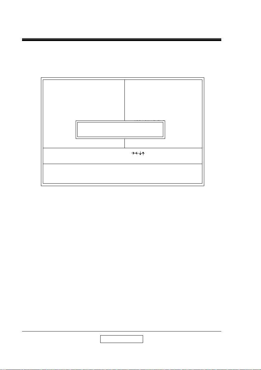
8. LOAD BIOS SETUP :
ROM PCI/ISA BIOS
POWER MANAGEMENT SETUP
AWARD SOFTWARE, INC.
STANDARD CMOS SETUP
BIOS FEATURES SETUP
CHIPSET FEATURES SETUP
POWER MANAGEMENT SETUP
PNP/PCI CONFIGURATION
LOAD BIOS DEFAULTS
LOAD SETUP DEFAULTS
LOAD BIOS DEFAULTS ( Y / N ) ? Y
INTEGRATED PERIPHERALS
SUPERVISOR PASSWORD
USER PASSWORD
IDE HDD AUTO DETECTION
HDD LOW LEVEL FORMAT
SAVE & EXIT SETUP
EXIT WITHOUT SAVING
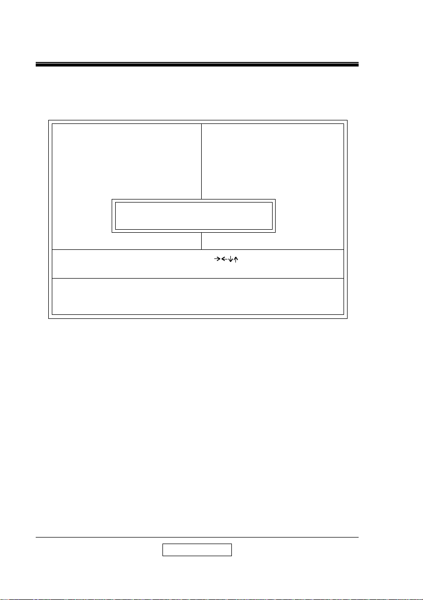
This Load BIOS Defaults option allows you to load the troubleshooting
default values permanently stored in the BIOS ROM . These default setting are
non-optimal and disable all high performance features. To load these default
setting, highlight Load BIOS Defaults on the main screen and then press the
<Enter> key. The system displays a confirmation massage on the screen. Press
the <Y> key and then the <Enter> key to confirm. Press the <N> key and then
the <Enter> key to abort. This feature does not affect the fields on the Standard
CMOS Setup screen.
User’ s Manual
Page 45
SETUP GUIDE
44
F10 : Save & Exit Setup (Shift)F2 : Change Color
9. LOAD SETUP DEFAULTS :
ROM PCI/ISA BIOS
POWER MANAGEMENT SETUP
AWARD SOFTWARE, INC.
STANDARD CMOS SETUP
BIOS FEATURES SETUP
CHIPSET FEATURES SETUP
POWER MANAGEMENT SETUP
PNP/PCI CONFIGURATION
LOAD BIOS DEFAULTS
LOAD SETUP DEFAULTS
Esc : Quit F5 : Manu in BIOS : Select Item
LOAD SETUP DEFAULTS ( Y / N ) ? Y
INTEGRATED PERIPHERALS
SUPERVISOR PASSWORD
USER PASSWORD
IDE HDD AUTO DETECTION
HDD LOW LEVEL FORMAT
SAVE & EXIT SETUP
EXIT WITHOUT SAVING
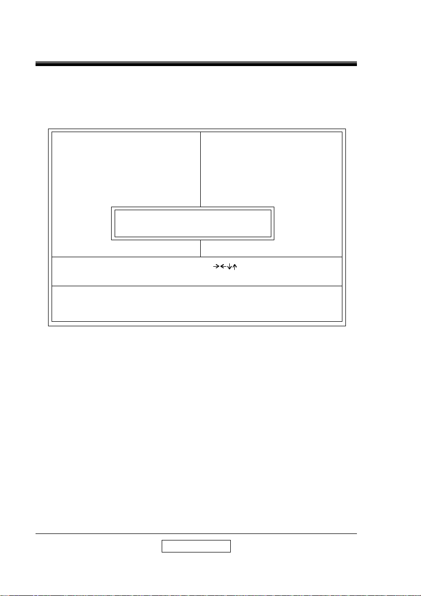
This Load Setup Defaults option allows you to load the default values to
the system configuration fields. These default values are the optimized
configuration settings for the system. To load these default values, highlight
Load Setup Defaults on the main screen and then press the <Enter> key. The
system displays a confirmation message on the screen. Press the <Y> key and
then the <Enter> key to confirm. Press the <N> key and then the <Enter> key to
abort. This feature does not affect the fields on the Standard CMOS Setup
screen.
User’ s Manual
Page 46
SETUP GUIDE
45
F10 : Save & Exit Setup (Shift)F2 : Change Color
10. SAVE AND EXIT SETUP :
ROM PCI/ISA BIOS
POWER MANAGEMENT SETUP
AWARD SOFTWARE, INC.
STANDARD CMOS SETUP
BIOS FEATURES SETUP
CHIPSET FEATURES SETUP
POWER MANAGEMENT SETUP
PNP/PCI CONFIGURATION
LOAD BIOS DEFAULTS
LOAD SETUP DEFAULTS
Esc : Quit b F5 : Manu in BIOS : Select Item
SAVE to CMOS and EXIT ( Y / N ) ? Y
INTEGRATED PERIPHERALS
SUPERVISOR PASSWORD
USER PASSWORD
IDE HDD AUTO DETECTION
HDD LOW LEVEL FORMAT
SAVE & EXIT SETUP
EXIT WITHOUT SAVING
Select this option to save into the CMOS memory all modifications you
specify during the current session. To save the configuration changes, highlight
the Save & Exit Setup option on the main screen and then press the <Enter>
key.
User’ s Manual
Page 47
SETUP GUIDE
46
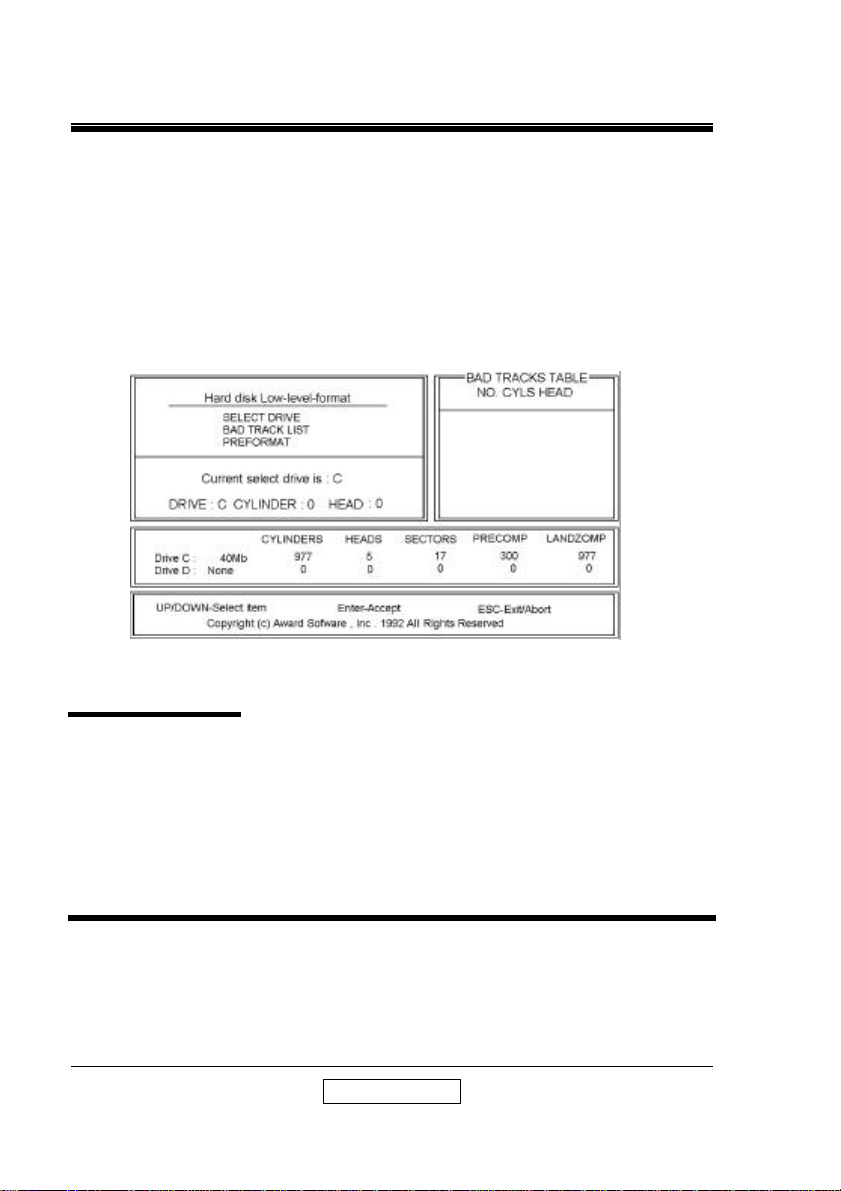
11. LOW-LEVEL FORMAT UTILITY :
formatting your hard disk. The Utility automatically looks for the necessary This
Award Low-Level-Format Utility is designed as a tool to save your time
information of the drive you selected. The Utility also searches for bad tracks
and lists them for your reference.
Shown below is the Main Menu after you enter into the Award Low-LevelFormat Utility.
Control Key
Use the Up and Down arrow keys to move around the
selections displayed on the upper screen. Press
<Enter> to accept the selection. Press <Esc> to abort
the selection or exit the Utility.
SELECT DRIVE
Select from installed hard disk drive C or D. Listed at the bottom of the
screen is the drive automatically detected by the utility.
User’ s Manual
Page 48

SETUP GUIDE
47
BAD TRACK LIST
Auto Scan Bad
Track
Add Bad Track
Modify Bad Track
Delete Bad Track
Clear Bad Track
Table
PREFORMAT
Interleave
The utility will automatically scan bad tracks and list the
bad tracks in the window at the right side of the screen.
Directly type in any information about known bad tracks
in the window at the right side of the screen.
Modify information about the added bad tracks in the
window at the right side of the screen.
Delete the added bad tracks in the window at the right
side of the screen.
Clear the whole bad track list in the window at the right
side of the screen.
Select the interleave number of the hard disk drive you
wish to perform low level format. You may select from
1 to 8. Check the documentation that came with the
drive for the correct interleave number, or select 0 for
utility automatic detection.
Auto Scan Bad
Track
Start
This allows the utility to scan for bad sectors first then
format by each track.
Press <Y> to start low level format.
User’ s Manual
Page 49

SETUP GUIDE
48
12. UPGRADE BIOS
The upgrade process requires two files from SUPERPOWER , the new BIOS file
(newbios.bin) and the upgrade utility (awdflash.exe).
RUNNING THE UPGRADE PROGRAM:
1. Boot system from the bootable floppy diskette you created. Booting from the
diskette bypasses loading drivers from the CONFIG.SYS and AUTOEXE.
BAT files on the hard drive, eliminating the possibility of loading a program
(a.g., a memory manager) that conflicts with the AWARD flash utility.
NOTE : The Award flash utility cannot run when EMM386 or
QEMM are loaded. If you try, an error message appears.
2. At the DOS command line, type AWDFLASH and press <Enter>.
3. The cursor should be opposite “FILE NAME to PROGRAM”
4. Type the name of the new BIOS file (e.g., newbios.bin), and press <Enter>.
5. At the bottom of the menu, this prompt appears:
Do you Want to Save BIOS (Y/N)?
6. If you DO NOT wish to save the old BIOS, type <N> and press <Enter>. Then
move to step 8.
If you DO wish to save the old BIOS, respond <Y>, and press <Enter>.
7. In the “File Name to Save” field, type a file name for the old BIOS (for
example, oldbios.bin), and press <Enter>.
Your old BIOS is saved in a file as named, in the default drive and directory
(in this example, on the A drive).
8. Then the program prompts you
Do You Want to Update? (Y/N)
9. If you DO NOT wish to update the BIOS, type <N> and press <Enter>. The
program exits to the command line. Skip the remainder of this section and go
directly to the next section.
If you DO wish to update the BIOS, respond <Y> and press <Enter>. When
the updating is finished, the following message appears:
Programming Flash Memory – 1FF00 OK
Please Power off or Reset System
10. Restart you system. You BIOS should be successfully update.
User’ s Manual
Page 50

SETUP GUIDE
49
This Board is Protected by Trend ChipAwayVirus Here’s
Why it Makes a Better Board:
Provides a virus-free boot and operating
system
Experience peace of mind though
hardware-base virus protection
Detects known and unknown boot viruses
with rule-based technology
Receive immediate protection! Already
installed on this board!
You’re right to be concerned about viruses. With over 2600 in existence, they
pose a very real threat to any PC user. They can strike in an instant, without
warning or prejudice – and erase gigabytes of data.
Boot Viruses pose the most severe threat because they can move from a floppy
diskette to your hard drive in less than a second. And it all happens during the
loading of the boot sector, making anti-virus programs that load through the
config.sys and autoexec.bat files worthless.
Finally, a Solution from Anti-virus expert*
Anti-virus software alone can’t do the job. But Trend ChipAwayVirus can make
up this deficiency. It’s a hardware-base anti-virus solution that stops virus
damage and infection through a proven rule-base anti-virus technology –
meaning it watches for virus behaviors rather than virus code.
So Trend ChipAwayVirus can catch both known and unknown viruses, including
mutation-engine viruses, both boot sector viruses, stealth viruses and general
viruses! For today and tomorrow.
And thanks to JumpLoadingTM technology, Trend ChipAwayVirus takes
control early in the boot cycle, before boot viruses have a chance to load. So the
entire boot process is virus-free and your computer boots to a clean operating
system.
User’ s Manual
Page 51
SETUP GUIDE
50
Peace of Mind For Your Customers
Best of all Trend ChipAwayVirus is here – on this board. So you can offer your
customers all the protection of Trend ChipAwayVirus just by choosing this board.
So choose Trend ChipAwayVirus. The same technology chosen for Intel
mother boards. You’ll be providing a quality board and peace of mind. That’ s
always a great combination!
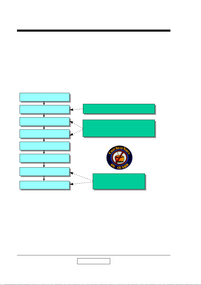
See how Trend ChipAway Virus protect your computer during the boot-up
procedure :
Power On
ROM BIOS Starts
ROM BIOS Starts
The Boot up Procedure of PC:
Ext BIOS Loads
Ext BIOS Loads
PartitionTable Loads
PartitionTable Loads
Boot Sector Loads
Boot Sector Loads
IO.SYS runs
IO.SYS runs
MSDOS.SYS runs
MSDOS.SYS runs
COMMAND.COM
COMMAND.COM
AUTOEXEC.BAT
AUTOEXEC.BAT
Finish Boot-up Procedure
TCAV loads here
TCAV loads here
Without TCAV,
Without TCAV,
a Virus can be loaded here
a Virus can be loaded here
Anti-virus program
Anti-virus program
loads here!
loads here!
User’ s Manual
 Loading...